1
CS5604 – Information Storage and Retrieval
Project Report
Generation of a User Interface Prototype
from an Integrated Scenario Specification
Project Members:
Colaso, Vikrant
Lobo, Lester
Shah, Anuj
Shastri, Priya
Client:
Kelapure, Rohit
Instructor:
Dr. Edward A. Fox
Fall, 2002
Generation of a User Interface Prototype from an Integrated Scenario Specification
Table of Contents
1. Introduction … … … … … … … … … … … … … … … … … … … .… … ..… … . .3
2. Design and Architecture Details....................................… … .............… .........4
2.1 Problems Faced … … … … … … … … … … … … … … … … … … … … … … .5
2.2 Project design… … … … … … … … … … … … … … … … … … … … … … … ..6
2.2.1 Modifications integrated into the SUIP design… … … … … .… … … … … … 6
2.2.2 Flow of control in the design… … … … … … … … … … … … … … … … … ...8
3. User Manual… … … … … … … … … … … … … … … … … … … … .… … … … ..9
Appendix A: Generated UIML code … … … … … … … … … ..… … … … … … ..10
Appendix B: Snapshot of the UI prototype … ..… … … … … … ..… … … … … ...12
References… … … … … … … … … … … … … … … … … … … … … … … … … … .13
2
Generation of a User Interface Prototype from an Integrated Scenario Specification
1. Introduction
This report discusses the design for the generation of a device independent user
interface prototype for services offered by a digital library from an Integrated Scenario
Specification using class diagrams and collaboration diagrams as input. The project was
conceived as an extension to the SUIP tool, which generates a User interface in java. But
this approach has an inherent problem. The interfaces thus generated have the java ‘look
and feel’ and this can’t be changed if the user so desires. Our design overcomes this
drawback by generating the interface in UIML which is device independent and thus it is
possible to render the code in java, HTML, WML and other languages.
The report aims at providing details about the intricacies of the design and the
tries to answer the common ‘how to’ questions to get the code running. In addition, it also
lists possible enhancements to the code that could be taken up as future work.
3
Generation of a User Interface Prototype from an Integrated Scenario Specification
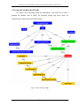
2. Design and Architecture Details
Our project was to basically extend the functionality of the SUIP tool so that it
generates the interface code in UIML. The following concept map shows where we
concentrated our efforts in the whole SUIP scenario.
Fig1: Project Concept Map
4
Generation of a User Interface Prototype from an Integrated Scenario Specification
As seen in the concept map the project involved converting the partial specifications
into the UIML code. To achieve this goal, we had to undertake several activities before
getting down to writing code for the final deliverable.
We took the following approach to realize our objective:
1. Understanding the SUIP algorithm in order to understand where our design would
fit into the code
2. Obtaining the latest UIML specification. (UIML v2.0 and v3.0)
3. Installing the UIML renderer. (LiquidUI)
4. Modifying the SUIP algorithm in order to integrate our design into the SUIP code.
5. Preparing a demonstrable prototype.
2.1 Problems Faced
We were faced with several problematic issues during the course of the project.
Some were due to our assumptions and the others were due to the non-standardization of
UIML. We have listed the hurdles that we faced below:
1. We started our design assuming that UIML had the ability to call functions across
files. However, we couldn’t find such functionality in the specification. We thus
had to abandon our initial design based on our assumptions. We decided to split
the files into 2 types - .stat and .act files. The .stat files contained the UI part,
which was static content. The .act files had the action listeners for the UI
components. The final output is a single file which concatenates the .stat and .act
files.
2. We realized that the UIML renderer renders only the older version of the UIML
specification much later and by this time we already had the UIML code
generated as per the latest specification. We ended up creating 2 deliverables so
that we had a demonstrable prototype.
3. One more difficulty was getting the UIML renderer (LiquidUI) up and running.
The documentation provided by the software is insufficient to do this. It took us
some time to realize that the software required jdk1.1 (now obsolete) for the
installation. However, the ironical part is that the same software requires jdk1.3 to
run.
5
Generation of a User Interface Prototype from an Integrated Scenario Specification
4.
Finally, we had problems regarding the SUIP code obtained from the authors
since the code provided had bugs. We had to debug this code before beginning
our design.
2.2 Logical Flow of the Design
The code written for our project modified 3 files of the original SUIP code:
1. UIGraph.java
2. Util.java
3. SUIP.java
The UIGraph.java file is concerned with the generation of the .stat and .act files from
the partial specifications generated by the SUIP code.
The Util.java file is concerned with the generation of the Main Window for SUIP and
the Simulation Window, which shows the transitions between the states of the state chart
diagram. The states correspond to the status of the UI components.
The SUIP.java file is the main application file, which starts the entire process and it
contains the code for combining the .stat and .act files into a single resultant file
“final.uiml”.
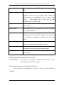
2.2.1 Modifications Integrated into the SUIP Design
The following functions were integrated into the UIGraph.java file:
Function Name
generateuimlFile
Function Description
This function was created in line with our initial approach of
creating multiple .uiml files which could call each other. This
function creates a .uiml file with the initial headers. Code for
generating the static content of the .uiml files has been
written. However, the further development on this approach
was abandoned because we couldn’t find a way of function
calling between .uiml files.
6
Generation of a User Interface Prototype from an Integrated Scenario Specification
generateuimlLwidget
This function generates the UIML equivalent of the java label
code.
generateuimlCwidget
This function generates the UIML equivalent of the java
Checkbox code. Since the renderer didn’t support the
checkbox group, we implemented this as a button group
having
radio buttons. This in effect had the same
functionality as the checkbox group
generateuimlBwidget
This function generates the UIML
equivalent of the java
button widget
generateStatFile
This function creates the .stat and .act files. It however
doesn’t populate the files.
generateUimlControllor
This function generates the UIML equivalent of the java
action listeners of the various UI components. In our project,
the action listeners correspond to button actions and menu
actions
ActivateUimlWidgets
This function generates the comments on state transitions
which are in turn displayed in the simulation window
DesactivateUimlWidgets
This function deactivates the UI components depending on
the transition of the states in the state transition diagram
chooseUimlScenario
This function generates the UI for choosing the regular or the
error scenario
The following function was modified in the Util.java file:
MenuForUIObject – This function was modified to generate UIML code for the main
SUIP terminal and the simulation window.
The following modifications were done in the SUIP.java file:
Code was written to concatenate the .stat and .act files into a single UIML file
“final.uiml”.
7
Generation of a User Interface Prototype from an Integrated Scenario Specification
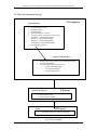
2.2.2 Flow of Control in the Design
UIGraph.java
generateFrame()
1.
2.
3.
4.
5.
Loop through Use Cases
generateuimlFile()
generateStatFile
Generate headers in .stat files
Loop through UI components in the use case
If textfield ? generateuimlIwidget()
If Label ? generateuimlLwidget()
If Button ? generateuimlBwidget()
If CheckBox ? generateuimlBwidget()
6. generateUimlControllor()
generateUimlControllor()
1.
2.
3.
Generate menu Action listener for the main SUIP terminal
ActivateUimlWidgets()
Loop through buttons in each use case
o DescativateUimlWidgets()
o ActivateUimlWidgets()
o ChooseUimlScenario()
[Util.java]
MenuForUIObject()
1.
2.
Creates SUIP Terminal
Creates Simulation window
[SUIP.java]
main()
1.
Concatenate .stat and .act files into final.uiml
Fig 2. Flow of Control
8
Generation of a User Interface Prototype from an Integrated Scenario Specification
3. User Manual
To use our deliverable following steps are to be taken.
1. Unzip the SuipSpec V2.0.zip to the destination folder
2. (Note: SuipSpec V3.0.zip can’t be rendered completely because UIML spec v3.0
can’t be rendered by the renderer)
3. Open a DOS window and go to the destination directory where the file has been
unzipped
4. Go to the SuipSpec V2.0\libprj\UIObjects\Terminal directory
5. On the command prompt type :
6. javac *.java
7. java SUIP classDiagramFile
8. This generates the final.uiml file, which is the output file to be rendered. The file
is created in the SuipSpec V2.0 directory
9. Download the UIML renderer LiquidUI. This can be downloaded at the following
link
10. http://www.harmonia.com/products/liquidui/download.htm
11. Install jdk1.1 since it is required for LiquidUI installation. This version is obsolete
but can be obtained from the archive at the following link:
12. http://java.sun.com/products/archive/index.html
13. Install jdk1.3 to run the renderer. This is a requirement by the renderer. The
jdk1.3 can be obtained at the following link
14. http://java.sun.com/j2se/1.3/download.html
15. Once the installation is complete and the final.uiml file has been generated it is
necessary to check if the vocabulary file(UIML2_0g.dtd) is present in the same
directory. If not place this file in the same directory as the output file.
16. The file “final.uiml” is now ready to be opened by the renderer, which then shows
the UI prototype.
9
Generation of a User Interface Prototype from an Integrated Scenario Specification
Appendix A: Generated UIML code sample
<?xml version="1.0"?>
<!DOCTYPE uiml PUBLIC "-//Harmonia//DTD UIML 2.0 Draft//EN" "UIML2_0g.dtd">
<uiml>
<interface id="myinterface">
<structure>
<part id="loan_Dialog1" class="JFrame">
<style>
<property name="title" part-name="loan_Dialog1">Choose
Scenarios</property>
<property name="size" part-name="loan_Dialog1">300,109</property>
<property name="layout">java.awt.BorderLayout</property>
<property name="visible">false</property>
</style>
<part id="loanD1Group1" class="ButtonGroup">
<part id="loanD1radio1" class="JRadioButton">
<style>
<property name="bounds">25,25,188,25</property>
<property name= "text"> {cancelLoan,regularLoan} </property>
<property name="enabled">true</property>
<property name="borderAlignment" >North </property>
</style>
</part>
<part id="loanD1radio2" class="JRadioButton">
<style>
<property name="bounds">25,50,125,25</property>
<property name="text">{errorUserLoan}</property>
<property name="enabled">true</property>
<property name="borderAlignment">Center</property>
</style>
</part>
</part>
</part>
</structure>
<behavior>
<rule>
<condition>
<event class="actionPerformed" part-name="loanD1radio1"/>
</condition>
<action>
<property part-name="txtArea1" name="content">DISPLAY
</property>
<property part-name="txtArea1" name="content"> <property partname="L 2" name="text"/></property>
10
Generation of a User Interface Prototype from an Integrated Scenario Specification
<property part-name="txtArea1" name="content"></property>
<property part-name="txtArea1" name="content">DISPLAY
</property>
<property part-name="txtArea1" name="content"> <property partname="L 3" name="text"/></property>
<property part-name="txtArea1" name="content"> </property>
<property part-name="txtArea1" name="content">DISPLAY
</property>
<property part-name="txtArea1" name="content"> <property partname="L 4" name="text"/></property>
<property part-name="txtArea1" name="content"> </property>
<property part-name="txtArea1" name="content">ENTER
</property>
<property part-name="txtArea1" name="content"> <property partname="L 5" name="text"/></property>
<property part-name="txtArea1" name="content"> </property>
<property part-name="txtFld5" name="enabled">true</property>
<property part-name="txtFld5" name="text"></property>
<property part-name="button2" name="enabled">true </property>
<property part-name="txtArea1" name="content">CLICK
BUTTON </property>
<property part-name="txtArea1" name="content">
<property part-name="button2" name="text"/></property>
<property part-name="txtArea1" name="content">
</property>
<property part-name="loan_Dialog1" name="visible">false
</property>
</action>
</rule>
</behavior>
</interface>
<peers>
<presentation source="Java_1.3_Harmonia_1.0.uiml#vocab"
base="Java_1.3_Harmonia_1.0"/>
</peers>
</uiml>
11
Generation of a User Interface Prototype from an Integrated Scenario Specification
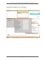
Appendix B: Snapshots of the UI prototype
12
Generation of a User Interface Prototype from an Integrated Scenario Specification
References
1.
Project page : http://collab.dlib.vt.edu/runwiki/wiki.pl?IsRprojKelapureThree
2.
Scenario synthesis algorithm 1: http://www.iro.umontreal.ca/labs/gelo/suip/GELO-82.pdf
3.
Scenario synthesis algorithm 2:
http://www.iro.umontreal.ca/~labgelo/Publications/Papers/ccpe-2001.pdf
4.
Scenario synthesis algorithm 3:
http://www.iro.umontreal.ca/labs/gelo/suip/bookChapter.pdf
5.
The SUIP tool for scenario-based prototyping: http://www.iro.umontreal.ca/labs/gelo/suip/
6.
UIML draft specification version 3.0 : http://www.uiml.org/specs/uiml3/DraftSpec.htm
7.
UIML draft specification version 2.0 : http://www.uiml.org/specs/uiml2/DraftSpec.htm
8.
List of java classes supported by the renderer:
http://www.uiml.org/toolkits/Java_1.3_Harmonia_1.0.uiml
13