Transcript
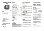
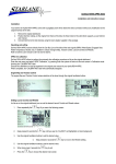
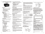
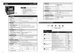
1. The Equipment is built-in type with Class II
construction and is protected by Reinforced
Insulation. Terminals are a part of the front panel
and are protected by means of finger guards.
Finger guards are not to be removed during wiring,
installation, operation or maintenance.
2. The power should be turned off while wiring and
maintenance to prevent the risk of electric shock.
Do not touch any terminals when the power is ON.
3. Wiring shall be done strictly according to the
terminal layout with shortest connections.
4. Fuse Protection: The equipment does not have
Built-in fuse. External fuse of rating 275 VDC/1 A is
recommended.
!
Caution:
1. For load current less
than 0.5A
m
22.5mm
100.5mm
4.
8
0m
230VAC
L
2. For bigger loads, use
interposing relay /
Contactor
230VAC
N
L N
A1
25
(L)
(COM2)
15
26
(COM1) (NC2)
11.5mm
A1
25
(L)
(COM2)
15
26
(COM1) (NC2)
Snubber
LOAD1
L
O
A
D
1
C
R
A2
CONTACTOR
28
16
NO
COM
A1
(NC1) (NO2)
18
(NO1)
L
16
28
(NC1) (NO2)
R
C
Snubber
A2
(N)
18
(NO1)
A2
(N)
1) Snubber Part No.: APRC - 01.
2) MOV Part No.: AP-MOV - 03.
Note: Use snubber as shown above to increase the
life of internal relay.
TERMINAL CONNECTIONS
S
U
P
P
L
Y
A1 25
TERMINAL
15 26
A1
L
T I M E R S U P P LY
A2
N
T I M E R S U P P LY
15
COM
NC
COM
NO
NC
COM
NO
16 28
18 A2
DESCRIPTION
16
NC
18
NO
25
COM
26
NC
28
NO
RELAY
CONTACT 1
RELAY
CONTACT 2
OPERATIN G MODE:
Supply
voltage
True NO
Power contact
off
delay
PANEL DIMENSIONS
t
t =Preset time
R
76.85
mm
7
8 9
10
75
35 mm
mm
6
5
4
3
ON
2 1
61.0mm
1. This unit is not intended for outdoor use.
2. The power connection cable must have a crosssection of atleast 1sq.mm and insulation capacity
of atleast 1.5kV. Use lugged terminals to meet M3
screws.
3. The output connections must not be loaded beyond
the specified values/range.
4. Avoid inflow of dust and contact of conductive
material with the internal circuitry of the unit.
5. Clean the equipment with a clean, soft cloth.
Do not use any organic solvents for cleaning.
TYPICAL LOAD CONNECTIONS
Supply Voltage
110 V to 240 VAC. (tolerance : -15 to
+10% AC: 50 or 60 Hz).
Delay Modes
True power off delay.
Time range
60 sec / 120sec / 180sec (factory set).
Output Contact
2 NO/NC.
Accuracy
Setting: ±10% of full scale.
Repeat: ± 2% or 100 msec
whichever is greater.
Led indication
Power ‘ON’.
Reset time
100 ms.
Relay rating
2.5 A @250 VAC / 28 VDC,
Resistive load ±10% for both V & I.
Mounting
Din rail / Screw mounting.
Size (in mm)
22.5(W) x 75(H) X 101(D).
Housing
CE marked products: Flame retardant
plastic.
Non CE products: ABS plastic.
Temperature
O
O
Operating: 0 C to 50 C.
O
O
Storage: - 20 C to 75 C.
Humidity Up to 95% RH.
115 grams.
Weight
10
Please maintain these instructions and
review them prior to using the unit:
! Warning :
SPECIFICATIONS
0
800POD
0
OPERATING INSTRUCTIONS
(Specifications subject to change as development is a
continuous process)
selectron
Process Controls Pvt. Ltd., India,
Tel : 91-22-28476443, Fax:91-22-28471733,
Website: www.selecindia.com; E- mail: [email protected]
105.5mm
Mounting holes
Document name: Operating / 0511/ 800POD / Version 1a
OP100 - V01a