Transcript
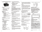
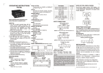
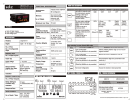
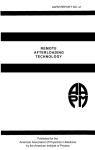
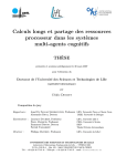
OPERATING INSTRUCTIONS
800XU
SPECIFICATIONS
SUPPLY VOLTAGE
20 to 240 VAC (AC@50 or 60Hz),12 to 240VDC
INPUT
Control contact.
OUTPUT CONTACT
2 C/O (DPDT)
RELAY RATING
5A @ 230 VAC/24 VDC, resistive.
DELAY MODES
On delay / Interval modes
TIME RANGES
1 / 3 / 10 / 30
Sec. / min / hr
ACCURACY
Setting: ± 5% of full scale.
Repeat: ±0.5% or 50 msec whichever is greater.
POWER CONSUMPTION
2 VA max.
LED INDICATION
Power ON.
Relay ON.
RESET : On interruption of power.
RESET TIME
Less than 100 msec.
SIZE (IN MM)
22.5 (W) x 75 (H) x 101 (D).
HOUSING
Flame retardant engineering plastic.
MOUNTING
DIN rail mounting.
Screw mounting.
TEMPERATURE
o
o
Operating: 0 C to 50 C.
o
o
Storage: 0 C to 50 C.
HUMIDITY
Up to 95% RH.
WEIGHT
115 grams.
10
0
2 1
0
3
ON
4.
35 75
mm mm
75
mm
85mm
1) Snubber Part No.: APRC - 01.
2) MOV Part No.: AP-MOV - 03.
Note: Use snubber as shown above to increase the life
of internal relay.
TERMINAL CONNECTIONS
A1 ( + )
A2 ( - )
1. The power supply should be switched off before removing
the equipment for cleaning. Ensure that no parts are
charged.
2. Clean the equipment with a clean, soft cloth. Do not use
any organic cleaning agent.
16
18
25
16 18
26 28
1
CONTACT
5A,250V AC/
24V DC, RESISTIVE
28
A2
ON DELAY
3
2 SCALE
1
4
TIME RANGE
SEC
3
MIN
10
HRS
30
HRS
INTERVAL
POWER
t
t
RELAY
t = Set time
TERMINAL
DESCRIPTION
A1
L ( + ) T I M E R S U P P LY
N ( - ) T I M E R S U P P LY
INSTALLATION GUIDELINES
A2
CAUTION:
1. The equipment is built-in type with Class II construction
15
COM
16
NC
and is protected by reinforced insulation. Terminals are a
part of the front panel and are protected by means of finger
guard. Finger guards are not to be removed during wiring,
installation, operation or maintenance.
2. Conductors must not come in contact with the internal
circuitry of the equipment as it may lead to a safety hazard.
3. Circuit breaker or main switch should be installed between
power source and supply terminals to facilitate power
ON/OFF function. This installation must be in a convenient
position normally accessible to the operator.
18
NO
25
26
NC
28
NO
DIR
5
MODE
ON DELAY
INTERVAL
RELAY
CONTACT 1
COM
RELAY
CONTACT 2
TYPICAL LOAD CONNECTIONS
MODES OF OPERATION
1. For load current less than 0.5A
230VAC
L
N
Fig1. On Delay:
Supply
Voltage
A1 25
CAUTION :
1. The equipment should not be installed in the
environmental conditions other than those mentioned in
this manual.
2. Fuse Protection: The equipment does not have a built-in
fuse. A fuse of rating 275 VAC/1Amp is recommended.
EMC Installation Guidelines:
1. Use proper input power cables with shortest connections
and twisted type.
2. Layout of connecting cables shall be away from any
internal emf source.
Mechanical Installation Guidelines:
1. The equipment uses a clamp for T type DIN rail only.
2. Ensure that the rail clamp is correctly fitted.
3. Slide the equipment using appropriate tools and holding
the unit from the front side, slide it over the fixed rail.
DIP SWITCH SETTINGS FOR SELECTION OF
DELAY MODES
SWITCH SETTINGS
SUPPLY: A1 (+), A2 (-)
AC: 50 / 60Hz
A1 25
15 26
MAINTENANCE
15
(L)
(COM2)
15 26
(COM1) (NC2)
Snubber
N/O Contact
NC Contact
L
O
A
D
1
C
R
t
16 28
(NC1)
t = set time delay
(NO2)
18 A2
(NO1)
Fig 2. Interval Delay:
(N)
Supply
Voltage
2. For bigger loads, use interposing relay/contactor
230VAC
L
N
N/O Contact
NC Contact
A1 25
(L)
t
(COM2)
15 26
(COM1) (NC2)
t = set time delay
CAUTION:
80
m
m
8 9
10
7
6
5
4
11.5mm
61.0mm
R
101mm
All safety related codification, symbols and instructions
that appear in this operating instruction manual must be
strictly observed to ensure operator as well as equipment
safety. The instruction manual is meant for personnel
involved in wiring, installation, operation and routine
maintenance of the equipment.
If the equipment related above safety measures are not
practiced, the manufacturer does not have any liability for
human or equipment safety.
CAUTION : Read complete instructions prior to
installation and operation of the unit.
CAUTION : Risk of electric shock.
WIRING GUIDELINES
PANEL DIMENSIONS
22.5mm
SAFETY SUMMARY
Mounting holes
1. The power should be turned off while wiring and
maintenance to prevent the risk of electric shock. Do not
touch the terminals when power is ON.
2. Wiring shall be done strictly according to the terminal
layout with shortest connections. Confirm that all the
connections are correct.
3. Use lugged terminals to meet M3 screws and ensure that
the screws are tightened .
LOAD 1
(Specifications subject to change as development is a
continuous process)
A2
CONTACTOR
NO
COM
Selec Controls Pvt. Ltd.
A1
16 28
(NC1)
C
R
Snubber
(NO2)
18 A2
(NO1)
(N)
(Formerly Selectron Process Controls Pvt. Ltd.)
Tel:91-22-28476443, Fax:91-22-28471733,
Website: www.selec.com
E- mail: [email protected]
Document name: Operating/0711/800XU/ Version 1
OP218-V01
Page 1 of 1