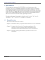
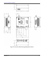
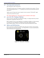
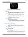
1
MICROLITE TRANSMITTER HD/SD COFDM Transmitter User Manual IMT PUBLICATION: M22-0005-00A, REV 1.0 microLite Transmitter User Manual Revision History Date Revision Modified By 0.0D DLA(MH) Initial release to approvers 0.1D 0.2D 0.3D (BETA) 0.4D DLA / MH MH MH DLA 01/25/2012 – 02/03/2012 ,5D SMV 02/05/12 1.0 SMV Ongoing updates and clarifications (WIP) Added regulatory text (FCC and IC) Updated to new form factor Updated LED indicator descriptions, 21MLT Updated Specifications, formatting, outline drawings, physical description. Added new models released. Added Appendix A. Initial Release 05/16/2011 06/13/2011 06/20/2011 08/17/2011 10/12/ 2011 11/15/2011 – Description MICROLITE TRANSMITTER User Manual IMT Publication: M22-0005-00A IMT, LLC. 200 International Drive Mt. Olive, NJ, 07828, USA. T +1 908 852 3700 F +1 908 813 0399 www.imt-solutions.com We make every effort to ensure our documentation is as accurate and as complete as possible. In the event that you find any errors or omissions, please contact Customer Tech Support at (908) 852-3700, or via email at [email protected]. © Copyrighted 2012 - IMT, LLC - Mount Olive, New Jersey 07828 Revision 1.0 2 microLite Transmitter User Manual This product has been approved by the following regulatory bodies at 5.8 GHz: FCC (USA) IC (Canada) CE (EU) CAUTION! RISK OF ELECTRICAL SHOCK. DO NOT REMOVE COVERS. Do not remove any covers Refer servicing to qualified technicians only Disconnect all power before servicing Read and perform all instructions carefully Failure to follow suggested instructions and guidelines may void all warranties PRUDENCE! RISQUE DE CHOC ÉLECTRIQUE. NE SUPPRIMEZ PAS LES COUVERTURES. Ne supprimez pas les couvertures Voir entretien à qualifiés Techniciens seulement. Déconnectez tous les pouvoir avant l'entretien. Lecture et effectuer toutes les instructions attentivement. Échec de suivre les lignes directrices et les instructions proposées peut-être annuler toutes les garanties. Revision 1.0 3 microLite Transmitter User Manual FCC STATEMENT This equipment (FCC ID: I4U-58MLT) has been tested and found to comply with the limits for a Class B digital device, pursuant to part 15 of the FCC Rules. DÉCLARATION DE FAC Cet équipement (FCC ID: I4U-58MLT) a été testé et de respecter les limites pour une classe b dispositif numérique, conformément à la partie 15 des règles de la FCC. FCC CAUTION/ PRUDENCE DE FAC Any change or modification not approved by the party responsible for compliance could void the user’s authority to operate this device. This device requires professional installation. For operation within 5.725 - 5.850 GHz frequency range, the maximum EIRP must be less than 36 dBm. The qualified antenna types to be used with this device include: Low Gain Collinear Omni Antenna (4.5dBi or 6 dBi) This device complies with Part 15 of the FCC Rules. Operation is subject to the following two conditions: (1) This device may not cause harmful interference, and (2) this device must accept any interference received, including interference that may cause undesired operation. In order to maintain compliance with the FCC RF exposure guidelines, this device should be installed and operated with a minimum distance of 20cm between the radiator, and the body of the operator and/or nearby persons. Tout changement ou modification non approuvé par la partie responsable de la conformité pouvait annuler l'autorisation de l'utilisateur pour l'exploitation de ce dispositif. Ce dispositif nécessite l'installation professionnelle. Pour l'opération au sein de la gamme de fréquences de 5.725-5.850 GHz, la pire maximale doit être inférieure à 36 dBm. Les types d'antenne qualifiés pour être utilisé avec ce dispositif, citons : Antenne Omni colinéaires faible Gain colinéaires Omni antenne (4.5dBi ou 6 dBi). Cet appareil est conforme à la partie 15 des règles de la FCC. Opération est soumis à deux conditions suivantes: (1) ce dispositif ne peut pas causer de brouillage préjudiciable, et (2) ce dispositif doit accepter toute ingérence a reçu, y compris le brouillage qui peut provoquer l'opération non désirée. Afin de maintenir la conformité avec les directives d'exposition RF FCC, ce dispositif doit être installé et exploité avec une distance minimale de 20 cm entre le radiateur et le corps de l'opérateur ou à proximité de personnes. Revision 1.0 4 microLite Transmitter User Manual IC Notice: IC Avis 1. Under Industry Canada regulations, this radio transmitter may only operate using an antenna of a type and maximum (or lesser) gain approved for the transmitter by Industry Canada. To reduce potential radio interference to other users, the antenna type and its gain should be so chosen that the equivalent isotropically radiated power (e.i.r.p.) is not more than that necessary for successful communication. Conformément à la réglementation d'Industrie Canada, le présent émetteur radio peut fonctionner avec une antenne d'un type et d'un gain maximal (ou inférieur) approuvé pour l'émetteur par Industrie Canada. Dans le but de réduire les risques de brouillage radioélectrique à l'intention des autres utilisateurs, il faut choisir le type d'antenne et son gain de sorte que la puissance isotrope rayonnée équivalente (p.i.r.e.) ne dépasse pas l'intensité nécessaire à l'établissement d'une communication satisfaisante. 2. This radio transmitter (IC: 9479A-58MLT) has been approved by Industry Canada to operate with the antenna types listed below with the maximum permissible gain and required antenna impedance for each antenna type indicated. Antenna types not included in this list, having a gain greater than the maximum gain indicated for that type, are strictly prohibited for use with this device. Le présent émetteur radio (identifier le dispositif par son numéro de certification ou son numéro de modèle s'il fait partie du matériel de catégorie I) a été approuvé par Industrie Canada pour fonctionner avec les types d'antenne énumérés ci-dessous et ayant un gain admissible maximal et l'impédance requise pour chaque type d'antenne. Les types d'antenne non inclus dans cette liste, ou dont le gain est supérieur au gain maximal indiqué, sont strictement interdits pour l'exploitation de l'émetteur. Antenna Approved/Antenne approuvé Max. Gain/Max. Type/Type Gain Collinear Omni Antennas/Colinéaires 6 dBi Omni antennes Impedance/Impédance 50 Ω 3. This device complies with Industry Canada licence-exempt RSS standard(s). Operation is subject to the following two conditions: (1) this device may not cause interference, and (2) this device must accept any interference, including interference that may cause undesired operation of the device. Le présent appareil est conforme aux CNR d'Industrie Canada applicables aux appareils radio exempts de licence. L'exploitation est autorisée aux deux conditions suivantes : (1) l'appareil ne doit pas produire de brouillage, et (2) l'utilisateur de l'appareil doit accepter tout brouillage radioélectrique subi, même si le brouillage est susceptible d'en compromettre le fonctionnement. Revision 1.0 5 microLite Transmitter User Manual 4. In order to maintain compliance with the IC RF exposure guidelines, this device should be installed and operated with a minimum distance of 20 cm between the radiator, and the body of the operator and/or nearby persons. Afin de maintenir la conformité avec les directives d'exposition RF IC, ce dispositif doit être installé et exploité avec une distance minimale de 20 cm entre le radiateur et le corps de l'opérateur ou à proximité de personnes. Revision 1.0 6 microLite Transmitter User Manual Revision 1.0 7 microLite Transmitter User Manual MICROLITE TRANSMITTER Contents 1 Introduction _________________________________________________________________ 12 1.1 2 User Manual Manual Overview_________________________________________________________ 12 microLite Description __________________________________________________________ 14 2.1 Theory of Operation ______________________________________________________ 15 2.1.1 Functional Block Diagram ______________________________________________________________ 2.1.2 Power, Remote Control, and User Data Interface Connector ____________________________________ 2.1.3 Audio and Video Input Connectors _______________________________________________________ 2.1.4 User Data Input_______________________________________________________________________ 2.1.5 MPEG4 Encoder (H.264 Part 10) _________________________________________________________ 2.1.6 COFDM Modulator ___________________________________________________________________ 2.1.7 RF Transmitter _______________________________________________________________________ 2.1.8 Remote Control and Firmware ___________________________________________________________ 2.1.8.1 Remote Control via Serial Interface __________________________________________________ 2.1.8.2 Firmware updates ________________________________________________________________ 2.2 MicroLite Physical Features and Interfaces ___________________________________ 17 2.3 External Signals __________________________________________________________ 20 2.4 RF Output_______________________________________________________________ 20 2.5 Connector Pin Assignment Information ______________________________________ 21 2.5.1 2.5.2 2.5.3 2.5.4 3 4 15 16 16 16 16 16 16 17 17 17 Power/Control Connector Pinout _________________________________________________________ Audio Input Connectors Pinout __________________________________________________________ Ext Connector Pinout __________________________________________________________________ Connector Part Numbers: _______________________________________________________________ 21 22 22 23 Specifications ________________________________________________________________ 25 3.1 RF _____________________________________________________________________ 25 3.2 Modulation Modes ________________________________________________________ 25 3.3 Video Modes supported ____________________________________________________ 25 3.4 MPEG Encoder __________________________________________________________ 26 3.5 System __________________________________________________________________ 26 3.6 Power Requirements ______________________________________________________ 26 3.7 Environmental ___________________________________________________________ 27 3.8 Physical Specifications_____________________________________________________ 27 3.9 Connectors ______________________________________________________________ 27 Operation ____________________________________________________________________ 29 4.1 microLite Set-up __________________________________________________________ 29 4.2 Powering Up the microLite _________________________________________________ 30 Revision 1.0 8 microLite Transmitter User Manual 4.3 microLite Pre-Configured Options ___________________________________________ 30 4.4 Button and LED Interface _________________________________________________ 30 4.4.1 Unit Interface Buttons _________________________________________________________________ 4.4.1.1 SET ___________________________________________________________________________ 4.4.1.2 TX/STBY ______________________________________________________________________ 4.4.1.3 Hi /LOW _______________________________________________________________________ 4.4.1.4 Bars or Fan _____________________________________________________________________ 4.4.2 User Interface Alarm Indicators __________________________________________________________ 4.4.2.1 Unit Fail or System Fail ___________________________________________________________ 4.4.2.2 Low Battery ____________________________________________________________________ 4.4.2.3 Over Temp/Fan Mode _____________________________________________________________ 4.4.2.4 Video __________________________________________________________________________ 31 31 31 31 31 31 31 31 31 32 4.5 Select User Level Settings __________________________________________________ 32 4.6 Put the unit in Transmit Mode ______________________________________________ 32 4.7 Select Power Level ________________________________________________________ 32 4.8 Operation Verification ____________________________________________________ 32 4.9 Accessory Kit ____________________________________________________________ 32 4.10 Maintenance Information __________________________________________________ 32 Figures Figure 2-1: Internal Block Diagram ___________________________________________________ 15 Figure 4-1: microLite Transmitter User Interface ________________________________________ 17 Figure 4-2: MLT Connectors_________________________________________________________ 17 Figure 4-4: microLite Outline Drawings (Dimensions in Inches) ____________________________ 19 Figure 4-5: Power/Control Connector Detail ____________________________________________ 21 Figure 4-6: Audio Connector Detail ___________________________________________________ 22 Figure 4-7: EXT Connector Detail ____________________________________________________ 22 Figure 4-3: Detail of Air Ducts _______________________________________________________ 29 Figure 5-1: Unit Interface - Broadcast ________________________________________________ 30 Figure 5-2: Unit Interface - Sports and Entertainment ____________________________________ 31 Tables Table 2-1: Summary of High Level Features and Benefits __________________________________ 14 Table 4-1: microLite Connectors______________________________________________________ 18 Table 4-2: Power and Control Cables__________________________________________________ 20 Table 4-3: Power/Control Pinout _____________________________________________________ 21 Table 4-4: Audio 1 & 2 Pinout _______________________________________________________ 22 Table 4-5: Ext Pinout_______________________________________________________________ 22 Revision 1.0 9 microLite Transmitter User Manual Table 3-1: Frequency Band Coverage _________________________________________________ 25 Table 3-2: Formats Supported _______________________________________________________ 25 Table 3-3: Environmental Specs ______________________________________________________ 27 Revision 1.0 10 microLite Transmitter User Manual Chapter One 1 Introduction Revision 1.0 11 microLite Transmitter User Manual 1 Introduction This document is a user manual for RF CENTRAL’s microLite microwave video transmitter. The microLite is a compact transmitter that digitally encodes video signals and transmits them using COFDM modulation over microwave frequencies. The unit accepts HD-SDI, SD-SDI, or composite video inputs in NTSC or PAL format, and can also accept User Data (e.g. NMEA GPS sentences) for transmission along with the main input signals. It has a built in MPEG4 (H.264 part 10 AVC) encoder and COFDM modulator. The microLite is housed in an ultra compact, lightweight enclosure. Throughout this manual, the product is referred to as the “microLite”, the “microLite Transmitter”, “MLT”, “microLite TX”, or simply the “transmitter.” 1.1 Manual Overview The contents of this manual are as follows: Chapter 2 – Describes the theory of operation and the features of microLite Transmitter. Chapter 3 – Contains a list of the microLite Transmitter specifications. The specifications include transmitter feature specifications, power requirements, environmental specifications, and I/O specifications. Chapter 4 – Describes operating and installation procedures for the microLite Transmitter. Revision 1.0 12 microLite Transmitter User Manual Chapter Two 2 Description Revision 1.0 13 microLite Transmitter User Manual 2 microLite Description This chapter describes the microLite transmitter theory of operation, features, and physical description. It also contains a block diagram of the MLT circuitry and a typical application example. The MLT has external connectors and features direct plug-in compatibility with off the shelf equipment using industry standard interfaces. The MLT internal circuitry encodes the audio and video signals, and organizes the compressed data into digital video transport streams. The transmitter uses COFDM modulation and transmits at microwave frequencies in the specific band supported by the unit. Though the unit ships pre-configured, a graphical user interface that runs on a Windows PC is available to modify the operating parameters. IMT has the ability, should the need ever arise, to provide the user with firmware files and instructions for local firmware installation, such as for feature upgrades, etc. Table 2-1: Summary of High Level Features and Benefits Feature Benefit COFDM Microwave Digital Video Transmitter Multiple Output Frequencies Microwave output frequencies in multiple bands. User orderable frequency band options. User programmable channels and offsets within band. Compatible with advanced video cameras. Compatible with industry standard SD video cameras. Direct audio input option for use with video signals that do not contain embedded audio. Direct SDI input for cameras with embedded audio. Industry standard compliant video compression. Implements latest algorithms for high quality. Data is transmitted along with audio and video to the receiver. Convenient menu and button based graphical user interface for Windows PC’s. Used to program the preset settings on the top panel. Fits in small form factor applications. ASI, HD-SDI, and SD-SDI Inputs NTSC or PAL Composite Video Inputs Stereo Audio Line Inputs Embedded Audios MPEG4 (H.264 Part 10) Encoder User Data Channel Remote Control GUI for Programming the MicroLite Compact Housing Revision 1.0 14 microLite Transmitter User Manual 2.1 Theory of Operation 2.1.1 Functional Block Diagram Major blocks in the MICROLITE TX include: Video Input Interfaces - ASI or HD-SDI, SD-SDI; NTSC or PAL Stereo Audio Input Interface MPEG4 Video Compression Circuit COFDM Modulator Microwave Transmitter and Antenna Connector Programmers Serial Interface for Remote Control Purposes Internal Microprocessor and Memory Power Circuitry Video Input Circuit (ASI, SDI) Audio Input Antenna MPEG4 Encoder COFDM Modulator Microwave Transmitter User Data Serial Port UI Buttons and LED’s Programmable Serial Port Microprocessor and Flash Memory Power Figure 2-1: Internal Block Diagram Revision 1.0 15 microLite Transmitter User Manual 2.1.2 Power, Remote Control, and User Data Interface Connector The microLite Transmitter Power, Remote Control, and User Data interface includes power and ground connections plus two RS-232 serial port interfaces. 2.1.3 Audio and Video Input Connectors The microLite TX has two analog audio inputs and one video input. They are used for stereo audio and HD/SD-SDI or NTSC/PAL video input. Refer to Chapter 3 for specifications of these signals. 2.1.4 User Data Input A data channel may be transmitted along with the audio and video information. The data channel is accessed through a RS-232 serial interface in the EXT connector. 2.1.5 MPEG4 Encoder (H.264 Part 10) The MLT encodes the input video signal before modulation and transmission to reduce bandwidth. The microLite TX contains a built-in MPEG4 (H.264 part 10) encoder for this purpose. The microLite TX features the latest compression methods utilizing I, P and B frames for more accurate encoding of compressed video signals. 2.1.6 COFDM Modulator The COFDM modulator receives data from the output of the MPEG4 AVC encoder through a circuit that enhances the security of transmissions. The microLite TX is able to transmit data at high data rates and with low error rates using COFDM modulation techniques. The data rate used by the transmitter depends upon the CODFM modulator settings used. 2.1.7 RF Transmitter The microLite microwave circuits mix the signal to the desired microwave frequency. The signal is filtered and boosted through a low noise output amplifier. The microLite TX has a single SMA style antenna connector. The output impedance of the antenna connector is 50 ohms. Note: On 5.8GHz models, the connector is RP-SMA due to FCC requirements. Refer to Chapter 3, “Specifications” for frequency band and channel tuning specifications. Revision 1.0 16 microLite Transmitter User Manual 2.1.8 Remote Control and Firmware 2.1.8.1 Remote Control via Serial Interface An RS-232 command set is implemented to allow remote control of all configuration options, as well as monitoring of internal status and settings. Commands and responses are sent via the RS-232 serial interface located on the Power/Control connector. The IMT NanoController GUI is available for controlling the unit via the RS232 serial interface. A Windows compatible computer running Windows XP or Vista with 500 MB of memory and 1 GHz Pentium or above can is needed. Refer to Chapter 4, “Operation” and the NanoController Manual (M27-000100A) for more information. 2.1.8.2 Firmware updates The unit firmware is updated via the USB interface on the Power/Control connector, using the IMT NanoTx Programmer software. A programming cable (IMT part number 922-B963-01A-R) is required. Contact IMT Tech Support for additional details. 2.2 MicroLite Physical Features and Interfaces Figure 2-2: microLite Transmitter User Interface Figure 2-3: MLT Connectors Revision 1.0 17 microLite Transmitter User Manual Table 2-2: microLite Connectors Connector (from left above) Label on Unit Description Lemo 7 pin Power & Control Power, USB, RS-232 Remote Control Interface Telocate Audio Left Audio Line Input Telocate Audio Right Audio Line Input Lemo 5 pin Ext ASI input, ASI Output, User Data, and USB BNC Video & SDI Composite NTSC or PAL Input, HD-SDI, SD-SDI Input ______________________________________________________________ ! WARNING – DO NOT OPEN THE microLite The microLite Transmitter contains no user serviceable parts. Do not open the microLite housing. Failure to comply will result in voiding of the warranty. ___________________________________________________________ Revision 1.0 18 microLite Transmitter User Manual Figure 2-4: microLite Outline Drawings (Dimensions in Inches) Revision 1.0 19 microLite Transmitter User Manual 2.3 External Signals The microLite connectors include the following major interfaces: Power and Ground Plus RS-232 programming interface (7 pin Lemo) Video Input Connector - accepts Composite Video, ASI, or SDI with appropriate cables (BNC) Analog Audio 1 and 2 Line/MIC Inputs (4 pin Telocate) User Data (5 pin Lemo) Table 2-3: Power and Control Cables IMT part # Cable Description 922-B964-01A-R 7pin LEMO to Tamiya Male connector 922-B962-01A-R 7pin LEMO to Tamiya Male connector, w/DB9 922-B973-01A-R 904-P088-00A-R Anton Bauer D-tap to Tamiya Female connector 12vDC Power Supply with Tamiya Female connector 2.4 Cable Type Power input cable Power input cable (w/Control) Source cable Source cable RF Output RF Out is a single SMA female connector. Note: Before applying power, ensure proper antenna termination is on RF output. Revision 1.0 20 microLite Transmitter User Manual 2.5 Connector Pin Assignment Information 2.5.1 Power/Control Connector Pinout Table 2-4: Power/Control Pinout Pin 1 2 3 4 5 6 7 Function +12VDC RS232 RX USB DM USB DP RS232 TX USB POWER GROUND Figure 2-5: Power/Control Connector Detail Revision 1.0 21 microLite Transmitter User Manual 2.5.2 Audio Input Connectors Pinout Table 2-5: Audio 1 & 2 Pinout Pin 1 2 3 4 Function LINE SELECT +5V MIC BIAS AUDIO IN GROUND Figure 2-6: Audio Connector Detail 2.5.3 Ext Connector Pinout Table 2-6: Ext Pinout Pin 1 2 3 4 5 Function GROUND ASI OUT RX User Data TX User Data ASI IN Figure 2-7: EXT Connector Detail Revision 1.0 22 microLite Transmitter User Manual 2.5.4 Connector Part Numbers: Revision 1.0 5 pin Lemo (on TX) ............... ECG.0B.305.CLN IMT PN ...................... 512-F3022-005-R 5 pin Lemo (mating) .............. FGG.0B.305.CLAD52 IMT PN ...................... 512-F3022-005-R 7 pin Lemo (on TX) ............... ECG.0B.307.CLN IMT PN ...................... 512-F3022-007-R 7 pin Lemo (mating) .............. FGG.0B.307.CLAD52 IMT PN ...................... 512-F3022-007-R 23 microLite Transmitter User Manual Chapter Three 3 Specifications Revision 1.0 24 microLite Transmitter User Manual 3 Specifications 3.1 RF Table 3-1: Frequency Band Coverage Base Part Number 21MLT-23-U3-C3 23MLT-23-U3-C3 58MLT-20-U3-C3 Frequency (GHz) 2.025-2.110 2.200-2.400 5.725-5.850 RF Power (dBm) 23 23 20 DC Power (W) 13 13 15 Tuning step size ............................................ 1 MHz step size (0.5Mhz for 21MLT model) Frequency stability......................................... ± 10ppm Standby mode ................................................ No RF output Normal .......................................................... Instant on-frequency transmission 3.2 Modulation Modes Modulation 1 Format: ............................................... COFDM (DVB-T) Carriers: ............................................. 2K Constellation: ..................................... QPSK, 16QAM Code Rate: ......................................... 1/2, 2/3, 3/4, 5/6, 7/8 Guard Interval: ................................... 1/32, 1/16, 1/8, 1/4 Bandwidth: ......................................... 6 MHz, 8 MHz 3.3 Video Modes supported Table 3-2: Formats Supported Revision 1.0 Standard Rate Mode Low Simple Long Advanced 720 59.94 p 4 frames n/a n/a n/a 720 50 p 4 frames n/a n/a n/a 720 29.97 p 4 frames n/a n/a n/a 720 25 p 4 frames n/a n/a n/a 720 24 p 4 frames n/a n/a n/a 720 23.98 p 4 frames n/a n/a n/a 1080 50 i 4 frames n/a n/a n/a 1080 29.97 p 4 frames n/a n/a n/a 1080 25 p 4 frames n/a n/a n/a 1080 24 p 4 frames n/a n/a n/a 1080 23.98 p 4 frames n/a n/a n/a 1080 29.97 psf 5 frames n/a n/a n/a 1080 25 psf 5 frames n/a n/a n/a 1080 24 psf 5 frames n/a n/a n/a 1080 23.98 psf 5 frames n/a n/a n/a 25 microLite Transmitter User Manual 3.4 MPEG Encoder Standard ....................................................... MPEG-4 Part 10 / H.264 AVC Video Video Coding ..................................... AVC Video Input: ....................................... Composite NTSC: ............................................... 720 x 480(4:2:0) PAL: .................................................. 720 x 576(4:2:0) SD-SDI input: .................................... ANSI/SMPTE 259M HD-SDI Input: ................................... ANSI/SMPTE 292M Audio Audio Coding: ................................... ISO/IEC 11172-3(Layer II) Audio Sample Rate: ........................... 48Khz Audio Channels: ............................... 1 Stereo, 2Mono Standard Audio Input: ....................................... Line; Single ended 1Vp-p (nom.) into 10K Ohms (-12dB to +50dB gain) ....................................................................... Mic, (-12dB to +50dB gain); 10K Ohms 5v Phantom power or Ext. Bias ....................................................................... De-embedded from SDI Tone .................................................. (-10dBfs/8dBm) Level Adj. (-10-26dBfs) 3.5 System Video Present: .......................................... Remote Standby/Test Generator Selectable Test Generator (Dynamic): ..................... SMPTE CB(NTSC)/100% CB(PAL) 16 Character ID (Match SDT Service name) 1.0 and 1.2kHz Tones ASI input:................................................. Rate converted from 0mpbs-Max modulation rate User Data: ................................................ RS232 Side channel (300-115K Baud) Remote Control:....................................... RS232 Local Control: .......................................... Key Board 3.6 Power Requirements Input range: DC: ...................................... +9 to +28 Power consumption: ............................... See table above Revision 1.0 26 microLite Transmitter User Manual 3.7 Environmental Table 3-3: Environmental Specs Item Specification Operational Temperature –10° to +50°C Ambient Temperature Range, Storage –40° to +80°C Humidity 0% to 95% RH, non-condensing Altitude, Operating 20,000ft (6,000m) maximum Altitude, Storage 50,000ft (15,000m) maximum 3.8 Physical Specifications Size (excluding connectors): ......................... 3.06” (78mm) x 1.59” (40.5mm) x 2.44” (62mm) Weight: ......................................................... 0.522lbs (237g) 3.9 Connectors Power, RS232 Control: L ........................ Lemo, 7 pin BNC Input: .............................................. Composite, HD-SDI, SD-SDI, or ASI Input Left and Right Audio: ............................. 4pin Telocate ASI Input B, ASI Output, User Data: ..... Lemo, 5 pin RF Output: .............................................. 50 Ohm RP-SMA (due to FCC requirement) Revision 1.0 27 microLite Transmitter User Manual Chapter Four 4 Operation Revision 1.0 28 microLite Transmitter User Manual 4 Operation While this chapter contains basic information about the operation of the microLite transmitter, the programming of the unit (including preset configuration) via the NanoController GUI is not covered. Please refer to the IMT NanoController manual (IMT Publication: M27-0001-00A) for detailed information on how to program and configure the unit. In this chapter, you will find info on how to use the microLite transmitter to transmit video, audio, and user data. 4.1 microLite Set-up Remove microLite Transmitter (MLT) from the case. Mounting bracket and Litepanels kit is preassembled. Attach assembly to camera. Connect video source to the Video/SDI Input (BNC jack) using a 75Ω BNC cable. Connect analog audio source (Telocate to XLR) to the transmitter using the two provided audio cables (if not using embedded audio). Connect TX antenna (small omni directional) to the RF output (SMA). Connect the power source to the MLT using the supplied transmitter power cable. Select the desired preset using the set button. Transmit signal using the MLT Tx/Standby button. Hi/Low button will control the power output level. microLite Transmitter will have one of the following button controls: o BARS – Will turn internal Bars on and off. o FAN – Will turn the internal fan on and off Note: The unit has an internal fan and the air ducts must not be blocked. Figure 4-1: Detail of Air Ducts Revision 1.0 29 microLite Transmitter User Manual 4.2 Powering Up the microLite Turn on the power to the overall system. The microLite requires up to 25 seconds to complete its internal power up sequence. The top row of front panel preset led’s (1, 2, 3, 4) light up in succession as the unit advances thru the boot process. Supply current will jump up in steps as internal circuits are powered. The final DC supply current will settle after 20 seconds. Note: Before applying power, ensure proper antenna termination on RF output. 4.3 microLite Pre-Configured Options The microLite has a wide range of programmable settings. It is shipped with factory default settings that are applicable to many use cases. Before using the microLite in your application, you should pre-configure it to for the settings you want to use in your application. Settings are selected and configured using the NanoController software. Please refer to the NanoController documentation for details. 4.4 Button and LED Interface The microLite has several buttons and LED’s on the front panel, which are used to perform basic operation and view basic unit status. Any changes made via a remote control interface will be reflected by the front panel LED’s. Figure 4-2: Unit Interface - Broadcast Revision 1.0 30 microLite Transmitter User Manual Figure 4-3: Unit Interface - Sports and Entertainment 4.4.1 Unit Interface Buttons 4.4.1.1 SET The Set button Advances the unit through the presets. The 1-12 LED’s indicate in GREEN, which preset is currently active. 4.4.1.2 TX/STBY The TX/STBY button toggles between Transmit and Standby modes. TX LED= Green for TX mode. Yellow LED for standby mode. 4.4.1.3 Hi /LOW The HI/LOW button toggles between High and Low Power modes. The Green LED for High power Yellow LED for Low power 4.4.1.4 Bars or Fan The MicroLite HD comes standard with either an external Bars or Fan control button depending what version you order. Bars - This is a push button switch pressing once changes to bars mode. Then push it once again to go back to video mode. Fan – This push button switches the fan on and off. 4.4.2 User Interface Alarm Indicators 4.4.2.1 Unit Fail or System Fail The LED will display Blinking YELLOW, which indicates an RF synthesizer lock failure. The unit will not transmit. Return unit to IMT for service. 4.4.2.2 Low Battery The LED will display Blinking YELLOW which indicates battery voltage < 9V. 4.4.2.3 Over Temp/Fan Mode Over Temp - The LED will display Blinking YELLOW that indicates internal temperature is too high. Check Fan operation or move to a lower ambient temperature. Fan Mode – The light is green when unit is cool enough to turn the fan off. Yellow indicates fan is off. Blinking yellow indicates fan is off but will automatically turn on in a minute. Revision 1.0 31 microLite Transmitter User Manual 4.4.2.4 Video The Video LED will display Green when Video is present on SDI input connector. Blinking YELLOW indicates that no video input signal (composite or SDI) is detected. This only detects the presence of video and does NOT detect if the encoder supports the format applied. See Section 3.3 for supported formats 4.5 Select User Level Settings By use of the SET button, select an appropriate preset so that your MicroLite transmitter and suitable receiver are on the same RF and modulation settings. 4.6 Put the unit in Transmit Mode Press the TX / STBY toggle button to put the unit in Transmit mode. Pressing the button again will put the unit in Standby mode (no RF output). 4.7 Select Power Level Press the HI / LOW toggle button to select the power level desired. In HI mode, the unit will output its full rated power. In LOW mode, the output will be approximately 6dB down from the HIGH power output. 4.8 Operation Verification Verify operation of the microLite by one of the following methods: If your system contains a host processor capable of communicating with the microLite via the serial interface, use interrogation commands to check the status of the microLite. Detect the transmitted signal using a spectrum analyzer. Using an appropriate receiver, verify that you are receiving audio and video from your application setup. 4.9 Accessory Kit The accessory kit with the MLT includes the following: 1 microLite HD Tx with transmitter mounting bracket and Litepanels kit - preassembled 1 Omni Directional Tx antenna 1Transmitter power cable set (Lemo to Tamiya) 1 Anton Bauer D-Tap power cable (D-Tap to Tamiya) 2 Audio cables (Telocate to XLR unbalanced) 1 USB-Serial adapters for configuring units (USB to RS-232) 1 USB/Power software update cable for system software updates for the MLT 1Transmitter power cable (Lemo to Tamiya/DB-9) 2 Instruction Manuals and NanoController Software on USB stick 4.10 Maintenance Information Follow these procedures when maintaining the device: Dry the device immediately if it is exposed to water or other liquids. Warranty does not cover liquid damage. Do not submerge the device or use it directly in rain. Revision 1.0 32 microLite Transmitter User Manual Revision 1.0 33 microLite Transmitter User Manual Do not open the device. This voids the warranty. Keep the device clean by wiping with a soft, dry cloth. If necessary, dampen only using a solution suitable for cleaning electronic devices. Warranty does not cover cleaning damage. Proprietary Information and Disclaimer Notice All information and graphic images contained within this manual are the sole property of IMT, LLC, and are issued in the strictest of confidence. This material may not be reproduced, stored, copied, or converted in any form, nor shall it be disclosed to others or used for manufacturing or any other purpose without the written permission of authorized IMT personnel. IMT has made every effort to ensure the accuracy of this material at the time of printing. However, as the specifications, equipment, and this manual are subject to change without notice, IMT assumes no responsibility or liability whatsoever for any errors or inaccuracies that may appear in this manual or for any decisions based on its use. This manual is supplied for informational purposes only and should not be construed as a commitment by IMT. Warranty Equipment manufactured by IMT, LLC is warranted to meet all published specifications and to be free from defects in material and workmanship within a period of two years from date of original shipment. The company’s liability under this warranty is limited to: Servicing or adjusting equipment. Replacement of defective parts. Any equipment returned to the factory shall have the freight paid for by the buyer. Equipment showing damage by misuse, abnormal conditions of operation, or attempts to repair by other than authorized service personnel shall be excluded from this warranty. IMT shall in no event be responsible for incidental injury or property damage. Since IMT has no control over conditions of use, no warranty is made or implied as to suitability for the customer’s intended use, beyond such performance specifications as are made part of the purchase order. There are no warranties expressed or implied, except as stated herein. This limitation on warranties shall not be modified by verbal representations. Shipping Damage Equipment shipped FOB IMT shall become the property of buyer upon delivery and receipt from carrier. Any damage in shipment should be handled by the buyer directly with the carrier. Immediately request the carrier’s inspection upon evidence of damage in shipment. Field Service IMT products are designed with easy access to components to facilitate service. However, some modules cannot be service in the field. To prevent voiding of the warranty, please contact Tech Revision 1.0 34 microLite Transmitter User Manual Support before servicing or making any repairs. The user is cautioned to read all module descriptions in this manual. Warnings are included in the circuit descriptions and on certain modules themselves. Replacement Modules Troubleshooting to the component level is often not cost-effective and frequently impossible. Often the practical method of effecting repairs is to substitute known good spare modules for suspect units. Replacement modules for our standard product line are usually available. Revision 1.0 35 microLite Transmitter User Manual Technical Support Information Technical Support personnel are available to extend technical assistance to customers while installing, operating, or troubleshooting IMT equipment. Please have your model number and serial number available. Telephone During IMT business hours, 8:30am - 5:30pm EST (-5 Hours, GMT), call: US ...................................................... 908-852-3700 International ....................................... 001-1-908-852-3700 After hours, call: US or International ............................ 888-531-3892 Email Email address ................................................. [email protected] Internet Web address ................................................... www.imt-solutions.com Equipment Returns If equipment cannot be successfully restored through telephone consultation, return to the factory may be required. Loaner items may be available until the repaired items are returned. For out-of-warranty equipment only: We evaluate all returned units, and then confers with the client on corrective action. If no fault is found, or no corrective action is authorized, a diagnostic fee may be charged. Prior to returning products to the factory, please obtain a return material authorization (RMA) number and shipping instructions from Tech Support. When returning equipment, it is very helpful to enclose a note containing the following: RMA number. Serial number. A detailed description of the problem. Name of an engineer or technician we may contact regarding problems encountered. A “ship to” and “bill to” address. Ship all returns to: IMT, LLC Attn: RMA# (your RMA number) 200 International Drive Mt. Olive, NJ, 07828, USA (908) 852-3700 For International returns: In addition to the instructions above, when shipping internationally we recommend the use of a courier such as Federal Express, UPS, etc, and that the goods be shipped DOOR-TO-DOOR PRE-PAID. This will reduce Customs costs, handling charges and delays. Enclose all the information above, plus a statement that the equipment was manufactured in the United States (the latter is needed to expedite customs processing). Revision 1.0 36 microLite Transmitter User Manual Revision 1.0 37 microLite Transmitter User Manual IMT, LLC. 200 International Drive Mt. Olive, NJ, 07828, USA. T +1 908 852 3700 F +1 908 813 0399 www.imt-solutions.com Revision 1.0 38