1
Moxa VPort 2310 Video Server
User’s Manual
Second Edition, June 2008
© 2008 Moxa Inc., all rights reserved.
Reproduction without permission is prohibited.
VPort 2310 User’s Manual
The software described in this manual is furnished under a license agreement and may be used only in
accordance with the terms of that agreement.
Copyright Notice
Copyright © 2005 Moxa Neworking Co., Ltd.
All rights reserved.
Reproduction without permission is prohibited.
Trademarks
MOXA is a registered trademark of the Moxa Group.
All other trademarks or registered marks in this manual belong to their respective manufacturers.
Disclaimer
Information in this document is subject to change without notice and does not represent a commitment on the
part of Moxa.
Moxa provides this document “as is,” without warranty of any kind, either expressed or implied, including, but
not limited to, its particular purpose. Moxa reserves the right to make improvements and/or changes to this
manual, or to the products and/or the programs described in this manual, at any time.
Information provided in this manual is intended to be accurate and reliable. However, Moxa Neworking assumes
no responsibility for its use, or for any infringements on the rights of third parties that may result from its use.
This product might include unintentional technical or typographical errors. Changes are periodically made to the
information herein to correct such errors, and these changes are incorporated into new editions of the
publication.
Technical Support Contact Information
www.moxa.com/support
Moxa Americas:
Toll-free: 1-888-669-2872
Tel: +1-714-528-6777
Fax: +1-714-528-6778
Moxa China (Shanghai office):
Toll-free: 800-820-5036
Tel: +86-21-5258-9955
Fax: +86-10-6872-3958
Moxa Europe:
Tel: +49-89-3 70 03 99-0
Fax: +49-89-3 70 03 99-99
Moxa Asia-Pacific:
Tel: +886-2-8919-1230
Fax: +886-2-8919-1231
Before getting started
Before using your VPort 2310, please pay close attention to the following items:
After opening the VPort 2310 box, compare the contents of the box with the Package Checklist in Chapter
1. Notify your sales representative if any of the items is missing or damaged.
To prevent damage or problems caused by improper usage, before assembling and operating the device and
peripherals, read the Quick Installation Guide (the printed handbook included in the package). You may
also refer to Chapter 1, under Product Description, and all of Chapter 2, of this manual.
If you experience a system error, and the system does not recover easily, refer to the Troubleshooting
section in Chapter 7 to learn how to restore factory default settings and reinstall the system.
The VPort 2310 Video Server has been designed for various environments and can be used to build various
applications for general security or demonstration purposes. For standard applications, refer Chapter 2,
Getting Started, and Chapter 3, Accessing VPort 2310 Video Server for the First Time.
Important Note
Surveillance devices may be prohibited by law in your country. Since VPort is both a high performance
surveillance system and networked video server, ensure that the operations of such devices are legal in your
locality before installing this unit for surveillance purposes.
Table of Contents
Chapter 1
Introduction ..................................................................................................1-1
Overview.................................................................................................................................. 1-2
Package Checklist .................................................................................................................... 1-3
Product Features ...................................................................................................................... 1-4
Typical Application.................................................................................................................. 1-4
Product Description ................................................................................................................. 1-5
Front Panel.................................................................................................................... 1-5
Rear Panel..................................................................................................................... 1-5
Chapter 2
Getting Started .............................................................................................2-1
Before Getting Started ............................................................................................................. 2-2
Hardware Installation............................................................................................................... 2-2
Assigning an IP Address .......................................................................................................... 2-3
DHCP Server Environment .......................................................................................... 2-3
Non-DHCP Server Environment .................................................................................. 2-4
Assigning the IP Address Manually ............................................................................. 2-5
Mounting VPort 2310 .............................................................................................................. 2-5
Panel Mounting............................................................................................................. 2-5
DIN-Rail Mounting ...................................................................................................... 2-5
Chapter 3
Accessing VPort 2310 for the First Time ...................................................3-1
Accessing VPort 2310.............................................................................................................. 3-2
Opening Your Browser................................................................................................. 3-2
Authentication .............................................................................................................. 3-2
Installing the Plug-in Application................................................................................. 3-3
Functions Featured on VPort’s Homepage............................................................................... 3-4
Logo and Host Name .................................................................................................... 3-4
Camera Image View ..................................................................................................... 3-4
System Configuration ................................................................................................... 3-4
Taking Snapshots.......................................................................................................... 3-4
Digital Zoom ................................................................................................................ 3-4
Relay Output Control.................................................................................................... 3-5
Motorized (PTZ) Camera Control ................................................................................ 3-5
Custom PTZ Camera Commands ................................................................................. 3-5
Client Settings............................................................................................................... 3-5
Chapter 4
System Configuration..................................................................................4-1
System Configuration via Web Access .................................................................................... 4-2
System .......................................................................................................................... 4-2
Security......................................................................................................................... 4-4
Network ........................................................................................................................ 4-5
DDNS & UPnP............................................................................................................. 4-8
Video .......................................................................................................................... 4-10
Motion Detection........................................................................................................ 4-13
Application ................................................................................................................. 4-15
Camera Control........................................................................................................... 4-19
Homepage Layout....................................................................................................... 4-23
View log file ............................................................................................................... 4-24
View parameters ......................................................................................................... 4-24
Factory default............................................................................................................ 4-25
System Configuration via FTP............................................................................................... 4-25
CONFIG.INI............................................................................................................... 4-25
System Configuration Via Telnet ........................................................................................... 4-32
Telnet Commands....................................................................................................... 4-32
System core debugging............................................................................................... 4-32
Monitoring changes to digital input status.................................................................. 4-32
Stop information dumping.......................................................................................... 4-32
Query status of digital inputs ...................................................................................... 4-32
Set digital outputs ....................................................................................................... 4-32
Erase snapshots stored in Flash memory .................................................................... 4-32
Skip installation at next boot ...................................................................................... 4-32
Erase logo and graphic buttons................................................................................... 4-33
Reset network ............................................................................................................. 4-33
Restore factory default settings................................................................................... 4-33
Reset system ............................................................................................................... 4-33
Chapter 5
Advanced Applications ...............................................................................5-1
Capturing Up-to-date Still Images ........................................................................................... 5-2
Getting snapshot via URL ............................................................................................ 5-2
Getting snapshot via FTP.............................................................................................. 5-2
Video Embedded in Customers’ Homepage............................................................................. 5-2
Download Event-triggered Snapshots...................................................................................... 5-3
Getting triggered snapshots via URL............................................................................ 5-3
Getting triggered snapshots via FTP............................................................................. 5-3
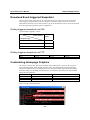
Customizing Homepage Graphics ........................................................................................... 5-3
URL Commands for DI/DO & Camera’s Actions Setting ....................................................... 5-4
Query status of digital inputs ........................................................................................ 5-4
Drive digital outputs ..................................................................................................... 5-4
Moving motorized camera in PTZ direction................................................................. 5-4
Recalling camera position............................................................................................. 5-4
Transparent Remote Serial Driver ................................................................................ 5-4
Sending commands to devices attached to the COM port ............................................ 5-5
URL Commands for System Maintenance............................................................................... 5-5
Download System Log via FTP.................................................................................... 5-5
Restart System via URL ............................................................................................... 5-5
Restore Factory Default Settings via URL ................................................................... 5-5
Chapter 6
Upgrading System Firmware ......................................................................6-1
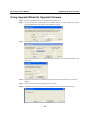
Using Upgrade Wizard to Upgrade Firmware.......................................................................... 6-2
Using FTP to Upgrade Firmware............................................................................................. 6-3
Chapter 7
Troubleshooting...........................................................................................7-1
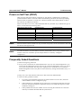
Power on Self Test (POST) ...................................................................................................... 7-2
Frequently Asked Questions .................................................................................................... 7-2
Appendix A URL Commands of Video Server............................................................... A-1
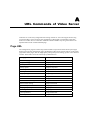
Page URL................................................................................................................................ A-1
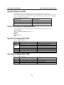
System Resource URL............................................................................................................ A-2
General Format of Command URL ........................................................................................ A-2
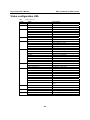
System Configuration URL .................................................................................................... A-2
Security configuration URL.................................................................................................... A-2
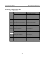
Network configuration URL ................................................................................................... A-3
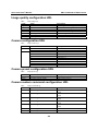
Video configuration URL ....................................................................................................... A-4
Image quality configuration URL ........................................................................................... A-5
Camera configuration URL..................................................................................................... A-5
Camera preset configuration URL .......................................................................................... A-5
Camera custom command configuration URL ....................................................................... A-5
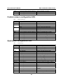
Custom camera configuration URL ........................................................................................ A-6
Application configuration URL .............................................................................................. A-6
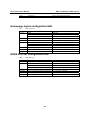
Homepage layout configuration URL..................................................................................... A-7
DDNS & UPNP configuration URL ....................................................................................... A-7
Appendix B Settings of Supported PTZ Cameras......................................................... B-1
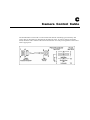
Appendix C Camera Control Cable ................................................................................ C-1
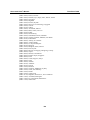
Appendix D Time Zone Table.......................................................................................... D-1
Appendix E Technical Specifications ............................................................................ E-1
1
Chapter 1
Introduction
VPort 2310 is a high-performance networking video server. In addition to meeting the basic needs
of video feed, many advanced features are included to help you set up surveillance or web
attraction applications. VPort 2310 is designed to provide stability, robustness, ease-of-use, and
flexibility.
The following topics are covered in this chapter:
Overview
Package Checklist
Product Features
Typical Application
Product Description
¾ Front Panel
¾ Rear Panel
VPort 2310 User’s Manual
Introduction
Overview
VPort 2310 is a 1-channel Video Server that adopts the high performance MPEG4 compression
algorithm to enhance the efficiency of video transmission via the IP network. Equipped with BNC
video input, image digitizer, image compressor (DSP) and 10/100 Mbps Ethernet connectivity,
VPort 2310 can digitize any analog video source and distribute these digital images over an IP
network, turning your CCTV system into a “Video over IP” Network System INSTANTLY. In
addition, VPort 2310 also provides synchronized Video/Audio output due to the adoption of
MPEG4 technology, giving the user a more realistic video/audio surveillance system.
High Performance MPEG4 compression
Video input can be efficiently compressed into packets of MPEG4 video stream without delay.
This is all done without sacrificing remote monitoring capability or storage. Five levels of
compression ratio and three different image resolutions are provided to provide more versatility.
Audio supported for a complete surveillance solution
The MPEGx series algorithm allows both voice and video to be compressed together to provide
users with more versatile applications, such as VCD (MPEG1), DVD (MPEG2), Internet
Multimedia Broadcast (MPEG4), etc. VPort 2310 introduces users to a brand new kind of
synchronized video/audio surveillance over IP network.
Easy Web access via standard browsers
There is no need to install new software to access the Video Server, since the embedded Web
Server allows users to use any popular web browser to access the Video Server from anywhere
over the Internet. As long as you are connected to the network, you will be able to view the same
images seen by your cameras.
User password protection
User password protection is provided to prevent malicious intruders from accessing your system.
Once the administrator password is configured, all users will need a password to access the Video
Server.
Built-in 3 area-selectable Video Motion Detection (VMD)
External sensors are not required, since the video channel can be configured to detect motion in 3
areas, making it easy to set up a security system in either your office or the field. And the
customizable settings allow you to tune the system for both object size and sensitivity, making the
Video Server adaptable to different environments.
Weekly schedule for automated surveillance
The user-defined time period will check security settings on a weekly basis, and send notifications
or drive external devices, making VPort 2310 suitable for more versatile applications.
Flexible I/O control for external devices
One opto-isolated sensor input and one relay output are provided to control external devices,
giving system integrators the option of turning an analog system into an advanced security system.
Moxa SoftDVR Lite IP Surveillance Software
To extend the Video Server’s capabilities, Moxa SoftDVR™ Lite IP Surveillance Software, which
supports a maximum of 4 cameras in quad, is included free of charge, allowing users to turn their
PC into a digital video recorder. Scheduling or one-click recording saves important images on
your local hard disk, and the reliable motion detection and instant warning features make you
ready for any situation. A quick and easy to use search and playback function lets you easily find
the image you’re looking for, so that you can inspect the images more carefully, and also save the
output to an AVI file.
1-2
VPort 2310 User’s Manual
Introduction
Remote system upgrade
Video Server users have round-the-clock access to the most up-to-date firmware on our website,
with a free upgrade wizard included to facilitate firmware installation.
Technical support for developers
The high-performance Video Server can be integrated into many applications—without busting
your budget—and the complete programming interface of Moxa ActiveX Control SDK makes the
developer’s job easy and straightforward. More ideas for Video Server applications can be found
on our website.
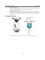
Package Checklist
1 VPort 2310 Video Server
Camera control cable
Power adaptor
Software CD
GPIO terminal block
Wrench
NOTE: Notify your sales representative if any of the above items is missing or damaged.
1-3
VPort 2310 User’s Manual
Introduction
Product Features
VPort 2310 products have the following features:
y Compact size, 1-ch MPEG4 Video Server
y 1 BNC video input and 1 RCA Audio Input
y Video stream up to 30 frames/sec in CIF (352 x 240) resolution
y Remote access with built-in web server for viewing and configuring
y Optimal solution by adjustable frame rate, bandwidth, and quality
y 3 area selectableVideo Motion Detection (VMD) with Pre/Event/Post images
y TCP, UDP and HTTP (No audio) client settings for network transmission
y Supports DDNS & UPnP protocols
y General I/O for external sensor and alarm
y Supports 1 RS-232/485 COM port for PTZ camera control
y Alarm with images transmitted via FTP or e-mail
y Password protection and administrator privilege
y Customized personal homepage
y Remotely upgrade the firmware to keep it up to date
y Moxa SoftDVR IP Surveillance Software for viewing and recording bundled free
NOTE: ActiveX Control SDK supports a flexible interface and sample codes for third-party
developers (contact a Moxa sales representatives for more information about this SDK).
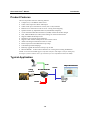
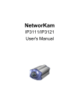
Typical Application
Audio
http://192.168.4.100
TCP/IP
Analog
Camera
IP: 192.168.4.100
Server
DI/ DO
1-4
VPort 2310 User’s Manual
Introduction
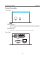
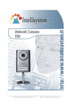
Product Description
Front Panel
VIDEO
IN
AUDIO
IN
BNC video input
The BNC video input is a 75 Ohm video port for connecting an external camera. To ensure that the
correct video modulation type is detected, cameras should be connected and powered on before the
VPort is powered on.
RCA audio input
The audio input is connected by an RCA connector, mono-audio line-in signal.
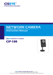
Rear Panel
1
INPUT
12 VDC
COM
RS-485
Relay
Output
NO
2
Digtal
Input
C: Common
NO: Normal Open
C
3
RESET
1: NETWORK
2: CONNECT
3: SERIAL
10/100 Mbps
Ethernet
COM
(RS-232)
1-5
VPort 2310 User’s Manual
Introduction
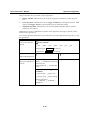
Network and Status LEDs
Each time the Video Server starts up, it performs a Power-On-Self-Test (POST) to examine each
hardware module. VPort 2310 Video Server has 3 LEDs:
1.
NETWORK: detects the network’s Tx/Rx status
2.
CONNECT: checks if the Video Server alive or not
3.
SERIAL: checks if the RS-232/485 COM port alive or not
As soon as the administrator plugs in the power connector, both the CONNECT and SERIAL
LED’s will flash, one by one, until the diagnosis is finished. If the result is okay, these 2 LEDs will
turn off momentarily, and then follow the pattern shown in the table below. If any of the modules
fails, refer to Chapter 7, Troubleshooting, under Power On Self Test for the error pattern, and
then follow the troubleshooting procedures. If the system still does not operate normally, contact
your reseller for technical service.
LED1
(NETWORK)
VPort’s IP is assigned
Flash
Ethernet alive
VPort’s IP is not assigned Flash
Ethernet defunct
OFF
During camera control
Flash
Condition
LED2
(CONNECT)
Flash
OFF
OFF
Flash
LED3
(SERIAL)
OFF
OFF
ON after 30 sec
Flash
10/100 Mbps Ethernet port
Use a UTP category 5 cable shorter than 100 meters to connect to an Ethernet network. Once the
Ethernet connection is established, the Video Server will use the Ethernet interface instead of the
modem attached to the COM port.
RS-232 COM port
If the Video Server is connected to the network via the Ethernet interface, you can use the RS-232
serial port to control a PTZ camera.
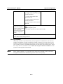
General I/O terminal block
COM RS-485
Relay Output
Digital Input
+
NO
C
+
Data+
DataNormal Open Max. 1A, 24 VDC or 0.5A, 125 VAC
COMMON
Short with Normal Close at the initial state
DIDI+
Max. 50 mA, 12 VDC
1-6
VPort 2310 User’s Manual
Introduction
The Video Server provides a very flexible general I/O interface that can be used with security
devices, such as sensors, alarms, lighting fixtures, or door locks. The general I/O terminal block
has six pins for device control. These pins can be divided into two categories based on the
interface being used (RS-485 or DI/DO).
RS-485 COM
If the device (such as a PTZ camera control) connected to COM has an RS-485 interface, wire the
RS-485 Data+ and Data- control lines to COM RS-485’s “+” pin and “ –” pin.
ATTENTION
Since RS-485 COM and RS-232 COM share the same UART chip, either RS-485 or RS-232 (but
not both) can be used.
Digital Input/Relay Output
VPort 2310 Video Server provides one digital input and one relay output. The Digital Input’s “+”
pin and “-” pin can be connected to an external sensor to monitor the voltage according to the
programmed scripts in configuration (see the “Command Script for DI/DO & Camera’s Actions
Setting” in Chapter 5). The Relay Output’s “NO” pin and “C” pin can be used to turn an external
alarm on or off.
Reset Button
A recessed RESET button is provided for restoring the system to the factory default settings.
When the system fails to install properly, or operates abnormally, use the wrench included in the
package to reset the system back to its original status. The procedure is as follows:
Step 1: Insert the wrench into the hole to press down on the reset button, which is located about
1.5 cm inside the surface of the casing.
Step 2: While keeping the reset button pressed, restart the system by powering off and on.
Step 3: The system will perform POST twice rather than the once. You can verify this by
observing the flashing “CONNECT” and “SERIAL” LEDs.
Step 4: After the system flashes the LEDs for the second time, withdraw the wrench to release the
button. The system will now be restored to the factory default settings.
12 VDC Power Adaptor
Connect the power jack of the included power adaptor. Connecting the power adaptor should be
the last step involved in the Video Server hardware installation.
1-7
2
Chapter 2
Getting Started
This chapter includes information about how to install a VPort 2310 Video Server.
The following topics are covered:
Before Getting Started
Hardware Installation
Assigning an IP Address
¾ DHCP Server Environment
¾ Non-DHCP Server Environment
¾ Assinging the IP Address Manually
Mounting VPort 2310
¾ Panel Mounting
¾ DIN-Rail Mounting
VPort 2310 User’s Manual
Getting Started
Before Getting Started
In what follows, “user” refers to those who can access the Video Server, and “administrator” refers
to the person who knows the root password that allows changes to the Video Server’s
configuration, in addition to providing general access. Administrators should read this part of the
manual carefully, especially during installation.
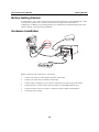
Hardware Installation
6
1
VIDEO
AUDIO
Front Panel
2
3
5
4
POWER
COLLISION
1
2
3
4
5
LINK
RECEIVE
PARTITION
Before powering on the Video Server, you should:
1.
Connect your camera’s video output to the BNC video input.
2.
Connect your audio source to the RCA audio input.
3.
Connect VPort’s COM port to your camera’s COM port if you are using a PTZ camera.
4.
Connect the hub or switch on the LAN to the VPort’s 10/100 Mbps Ethernet port.
5.
Connect I/O devices (such as sensors or alarms) to VPort’s GPIO Terminal Block.
6.
Connect the power supply.
2-2
VPort 2310 User’s Manual
Getting Started
Assigning an IP Address
DHCP Server Environment
In this case, the IP address of VPort 2310 is assigned by a DHCP Server. Use the DHCP Server’s
IP address table, or use the Moxa IP Reporter utility to determine the IP address that was assigned
by the DHCP Server.
NOTE
After powering on the VPort 2310, wait a few seconds for the POST (Power On Self Test) to
run. The IP address will be assigned when the CONNECT LED is lit.
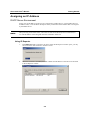
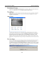
Using IP Reporter
1.
Run IPReporter.exe to search for the VPort. After the IP Reporter window opens, you may
also click on the Search button to initiate a search.
2.
When the search has concluded, the MAC address and IP address of the VPort will be listed
in the IP Reporter window.
2-3
VPort 2310 User’s Manual
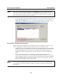
NOTE
Getting Started
If the VPort has been assigned an IP address, the Assigned status will be listed as Yes. If the
VPort has not been assigned an IP address, the Assigned status will not be listed as Yes. In this
case, check to see if the VPort’s firmware version supports the DHCP installation function, or if
there is any problem with the network environment.
3.
Click on the VPort whose MAC address matches the one you just installed, and then click on
Link to the selected device to access the VPort via your web browser. You will be able to
modify VPort’s IP address and other settings when the VPort’s homepage opens.
Non-DHCP Server Environment
If your VPort 2310 is connected to a network that does not have a DHCP server, then you will
need to configure the IP address manually. There are two ways to access the server:
1. If one VPort 2310 is connected to the network, open your web browser and type the default
IP address in the browser’s address box. In this case, the default IP address is 192.168.0.99
and the default subnet mask is 255.255.255.0. Note that you may need to change your
computer’s IP address and subnet mask so that the computer is on the same subnet as the
VPort.
2.
NOTE
If two or more VPort 2310s are connected to the network, default IP addresses of
192.168.0.99, 192.168.0.100, etc., will be assigned to the VPorts. In this case, you can use
Moxa’s IP Reporter utility to locate each VPort connected to the network. Since IP Reporter
searches by MAC address, the VPort and computer just need to be connected to the same
Ethernet LAN for IP Reporter to locate the VPort.
VPort’s Network and Status LEDs can be used to determine if the VPort is transmitting and
receiving data over the network. Refer to Chapter 1 to see how to interpret the Network and
Status LEDs.
2-4
VPort 2310 User’s Manual
Getting Started
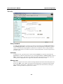
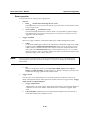
Assigning the IP Address Manually
To change the IP address of VPort manually, access VPort’s web server, and then navigate to the
Configuration Æ Network page to configure the IP address and other network settings. Uncheck
the Reset IP address at next boot to ensure that the IP address you assign is not deleted each time
the VPort is restarted.
uncheck to keep VPort’s
Fix VPort’s IP
IP fixed
Change IP and network
setting manually
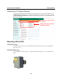
Mounting VPort 2310
Panel Mounting
The VPort 2310 Video Server can be mounted directly to the wall using 2 screws with diameter
larger than 7 mm.
DIN-Rail Mounting
A 35 mm DIN-Rail mounting option—the DK-35 DIN-Rail mounting kit—can be ordered from
Moxa.
2-5
3
Chapter 3
Accessing VPort 2310 for the First Time
This chapter includes information about how to access VPort 2310 Video Server for the first time.
The following topics are covered:
Accessing VPort 2310
¾ Opening Your Browser
¾ Authentication
¾ Installing the Plug-in Application
Functions Featured NPort’s Homepage
¾ Logo and Host Name
¾ Camera Image View
¾ System Configuration
¾ Taking Snapshots
¾ Digital Zoom
¾ Relay Output Control
¾ Motorized (PTZ) Camera Control
¾ Custom PTZ Camera Commands
¾ Client Settings
VPort 2310 User’s Manual
Accessing VPort 2310 Video Server for the First Time
Accessing VPort 2310
Opening Your Browser
Open your browser, type the VPort’s IP address in the Address box, and then press Enter.
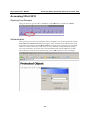
Authentication
After opening your browser and typing the VPort’s IP address, you will be requested to enter the
User name and the Password. When accessing the VPort for the first time, administrators must
enter root as the username, and the MAC address, in capital letters, as the password. The MAC
address is located on the VPort’s back panel, or can be found by running IP Reporter. Primary
users will be allowed to access the VPort when the administrator finishes adding user profiles.
After entering a valid User name and Password, click on OK to open the VPort’s homepage.
3-2
VPort 2310 User’s Manual
NOTE
Accessing VPort 2310 Video Server for the First Time
The MAC address is located on the VPort 2310’s back panel. It is also shown in the IP Reporter
window after the VPort has been located.
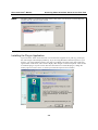
Installing the Plug-in Application
If you access the VPort for the first time via a browser that supports server push (e.g., Netscape),
the video images will be displayed directly. If you are using Windows’ Internet Explorer as your
browser, you will be asked to install a new plug-in provided by the VPort. This plug-in has been
registered for certification, and is used to display video images via Internet Explorer. Click on Yes
to install the plug-in. If your browser does not allow the user to install the plug-in, change the
security option to a lower level, or contact your network supervisor for assistance.
3-3
VPort 2310 User’s Manual
Accessing VPort 2310 Video Server for the First Time
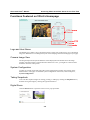
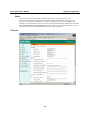
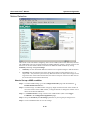
Functions Featured on VPort’s Homepage
PTZ Camera
Control
Custom PTZ
Camera
Commands
Logo and Host Name
The default logo is Moxa’s logo, and the host name is VPort 2310 Video Server. For customized
usage, the administrator can change the layout of the homepage from the Homepage Layout page.
Camera Image View
The assigned caption and system date/time will be displayed in the banner above the image
window. Note that if VPort’s motion detection function is active, you might see some windows
framed in red in the video picture.
System Configuration
A button or text link on the left side of the system configuration window only appears on the
administrators’ main page. For detailed system configuration instructions, refer to Chapter 4,
System Configuration.
Taking Snapshots
Users can take snapshot images for storing, printing, or editing by clicking the Snapshot button,
and then saving the image by clicking the right mouse button.
Digital Zoom
Click the Zoom button to open the zoom tool in a pop-up window.
3-4
VPort 2310 User’s Manual
Accessing VPort 2310 Video Server for the First Time
Relay Output Control
VPort 2310 Video Server has 1 DI/DO for external devices, such as sensors and alarms. If external
devices are attached to the digital output, administrators or permitted users can click on Open to
short the Common and Normal Open pins of the digital output, or click on Close to short the
Common and Normal Close pins of the digital output.
Motorized (PTZ) Camera Control
If a serial device, such as a motorized camera, is attached to the COM port, the control panel will
appear on the main page of user’s who have permission to operate the camera. The active buttons
will change color when the cursor is passed over the button. Users can control the pan, tilt, zoom,
and focus functions of motorized cameras. The home button is used to return the camera to the
center position if the camera supports this command. In addition to near and far control for focus,
an AUTO button is provided for setting auto focus mode. To move the motorized camera more
precisely, the speed control for pan and tilt allows users to fine tune the aiming of the camera.
Users can also click directly on any point in the image to force the motorized camera to focus on
that point, or select a preset location from the drop-down menu. The list of preset locations is
pre-defined by administrators. The detailed configurations are described in the related section in
Chapter 4, System Configuration.
NOTE
For some PTZ cameras, users can click on any position on the image to point the camera at that
position. We currently support this functionality on Sony EVID30, Cannon VCC4, and Pelco-D
PTZ cameras.
Custom PTZ Camera Commands
In addition to the default pan, tilt, zoom, and focus controls, an additional five buttons are
available for custom commands to control the attached motorized (PTZ) cameras. Custom
commands are set up by administrators, and are used for functions such as activating or
deactivating the wiper of dome. Refer to the attached motorized device’s User’s Manual to see wat
kind of functions can be controlled with these additional buttons.
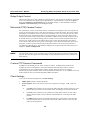
Client Settings
Users can set the following functions in Client Settings.
1.
Media option: enable or disable the audio.
2.
Protocol option: choose one of three protocols to optimize your usage—UDP, TCP, and
HTTP.
¾
The UDP protocol allows for more real-time audio and video streams. However, some
packets may be lost due to network burst traffic, and images may become obscured.
¾
The TCP protocol allows for less packet loss, and produces a more accurate video
display. The downside of TCP is that the real-time effect is worse than with UDP
protocol.
¾
The HTTP protocol must be selected if the network is protected by a firewall and it
only allows HTTP Port to be opened. In this mode, audio will not be sent. Only the
video will be operational.
3-5
VPort 2310 User’s Manual
Accessing VPort 2310 Video Server for the First Time
Most users choose protocols in the sequence UDP Æ TCP Æ HTTP. Once the Video
Server is connected successfully, “Protocol Option” will indicate the selected protocol. The
selected protocol will be recorded in the user's PC and will be used for the next connection.
If the network environment is changed, or you want to refresh the web browser, manually
select the UDP protocol, save, and then return HOME to re-connect.
3-6
4
Chapter 4
System Configuration
After installing the hardware, the next task required is to configure VPort 2310’s settings.You may
use one of three configuration methods: via web access, via FTP, and via Telnet.
This chapter includes the following sections:
System Configuration Via Web Access
¾ System
¾ Security
¾ Network
¾ DDNS & UPnP
¾ Video
¾ Motion Detection
¾ Application
¾ Camera Control
¾ Homepage Layout
¾ View log file
¾ View parameters
¾ Factory default
System Configuration Via FTP
¾ CONFIG ini
System Configuration Via Telnet
¾ Telnet Commands
¾ System core debugging
¾ Monitor changes to the digital input status
¾ Stop information dumping
¾ Query status of digital inputs
¾ Set digital outputs
¾ Erase snapshots stored in Flash memory
¾ Erase logo and graphic buttons
¾ Reset network to new settings
¾ Restore facotry default settings
¾ Reset system
VPort 2310 User’s Manual
System Configuration
System Configuration via Web Access
System configuration can be done remotely with Internet Explorer via the Web Server.
Alternatively, administrators may type the system configuration URL, “http://<IP address of Video
Server>/setup/config.html”, to enter the configuration page directly. Administrators who wish to
set up certain options by using the URL should refer to the relevant section in Chapter 6, “URL
Commands,” for advanced functions.
Five types of configuration are involved in configuring the system:
1.
Since VPort 2310 Video Server is a networked video server, administrators should configure
Security, Network, Video, and DDNS & UPnP.
2.
To support PTZ camera control, administrators should configure Camera Control.
3.
To utilize the built-in security and web attraction features, administrators should configure
Motion Detection and Application.
4.
Administrators can adjust the system date and time under System, or configure different
homepage layouts by configuring Homepage layout.
5.
Video Server also provides other system maintenance options, including View log file, View
parameters, and Factory default.
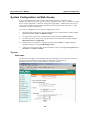
System
Host name
The host name will appear as the homepage title of the main page and over the video window on
the main page. The maximum string length is 40 characters or 20 characters in
double-byte-character systems, such as Chinese or Japanese systems.
4-2
VPort 2310 User’s Manual
System Configuration
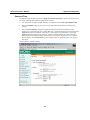
Date and Time
The default setting for Date and Time is Keep current date and time. You may also choose from
one of the following date and time configuration options:
1.
The easiest way to adjust the date and time is to make the VPort Sync with computer time.
2.
Select the Manual option if you wish to set the date and time manually by entering new
settings.
3.
Select the Automatical [sic]option to make the VPort synchronize automatically with
timeservers over the Internet every month. However, synchronization may fail if the assigned
NTP server cannot be reached, or the VPort is connected to a local network. Leaving the
NTP server blank will force the VPort to connect to default timeservers. Enter either the
Domain name or IP address format of the timeserver as long as the DNS server is available.
Do not forget to set the Time zone for local settings. Refer to Appendix G for your region’s
time zone.
Click on Save to validate changes.
4-3
VPort 2310 User’s Manual
System Configuration
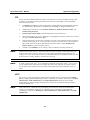
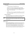
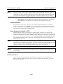
Security
Root password
To change the administrator’s password, type the new password in both the Root password box
and Confirm password box. The passwords you enter will be displayed in asterisks for security
reasons. The maximum string length for a password is 14 characters. After clicking on Save to
validate the new password, a window will open to ask the administrator for the new password to
access the VPort.
Add user
To add a new user, type the new user’s name in the Username box, the password in the User
password box, and select authorization level by checking I/O access or Camera control. Click on
Add to insert the entry. The VPort 2310 Video Server has a total of 20 user accounts. Each user
can be given an independent access right to the external I/O and camera control.
Manage user
If the access rights of some users need to be changed, find the user name from the drop down list
and click on Edit. A new window will appear for the administrator to change the password and
select a different authorization. Administrators can also delete the selected user by clicking on
Delete. A message window will open next to confirm.
4-4
VPort 2310 User’s Manual
System Configuration
Demo
VPort 2310 Video Server provides a demonstration mode to allow general access for
demonstration purposes. To set up the demonstration mode, administrators must choose the
services to be permitted. If administrators select the view option, users may use demo as the
username to access the VPort. In this case, leave the password field blank. Administrators can also
select control camera or control DO options for the demo account. Separating the demo account
from the primary users can prevent interference with normal operations.
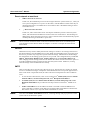
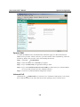
Network
4-5
VPort 2310 User’s Manual
System Configuration
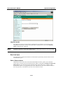
Reset network at next boot
1.
; Reset network at next boot
In this case, the installation process will be run again when the system reboots (i.e., when you
save system configuration or re-power on the VPort). The IP address of VPort 2310 may be
changed if the VPort is in a DHCP Server environment. This is the default setting of VPort
2310 Video Server.
2.
□ Reset network at next boot
In this case, VPort 2310 Video Server will skip the installation process at the next system
reboot, which means the IP address is fixed to VPort 2310 Video Server. The advantage of
disabling the “Reset network at next boot” option is that the VPort will automatically operate
normally after being restarted after a power loss.
NOTE
VPort’s Network and Status LEDs can be used to determine if the VPort is transmitting and
receiving data over the network. Refer to Chapter 1 to see how to interpret the Network and
Status LEDs.
General
Administrators may need to modify the network settings to connect to an existing network since
the subnet mask for some broadband services may differ from the default value of 255.255.255.0,
and service providers may assign more specific network settings. Administrators should change
the configuration to the settings given by the service provider. The configuration may include IP
address, Subnet mask, Default router, Primary DNS server, and Secondary DNS server.
After changing network settings, make sure to uncheck the “Reset network at next boot option” to
avoid the installation starting up again the next time the system restarts. Otherwise, existing
network settings will be erased at the next startup.
SMTP
VPort 2310 Video Server not only plays the role of server, but also actively connects to outside
servers to send alarm messages or snapshots. If the administrator has set up some applications in
either event mode or sequential mode, the VPort will send out snapshots once these conditions
occur.
NOTE
1.
To activate the e-mail function, enter correct settings for 1st SMTP (mail) server’s domain
name/IP address, account name/password, and 1st Recipient email address.
2.
2nd SMTP (mail) server’s domain name/IP address, account name/password, and 2nd
Recipient email address are provided for a backup connection when the 1st SMTP server
fails.
3.
Sender email address is for the address the email is returned to when the SMTP server
rejects email due to a failure. Some ISPs may need the sender email address to determine if
this email is valid or not, or reject the email if the address is invalid.
Note that if the Sender email address is not set, a warning message will pop up and the e-mail
system will not be allowed to operate.
4-6
VPort 2310 User’s Manual
System Configuration
FTP
FTP is the other method available for VPort 2310 Video Server to send out alarm messages and
snapshots. To send the system log files described in the above paragraph via FTP, the SMTP
server should be erased.
1.
Local FTP server port can also be changed to a setting different from the default setting of
21. Administrators should have enough network knowledge to change the default port.
2.
Administrators must enter correct Primary FTP Server, Primary FTP user name, and
Primary FTP password.
3.
Primary FTP remote folder is the sub-folder in the remote FTP server.
4.
If the remote FTP server’s port is changed to a setting different from 21, make sure to set the
real port to Primary FTP server port.
5.
If the local network is protected by a firewall to prevent it from initiating an FTP connection
from the remote FTP server, you may be able to connect to the FTP server, but be unable to
place a file on the server due to data channel connection failure. Check Primary FTP
passive mode for a passive transfer solution.
6.
Another set of Secondary server settings is also provided for a backup connection.
NOTE
Whenever the system reboots, a system log will be sent out via email or FTP to show the login
status of VPort. The system log will be sent to the Sender email address if the SMTP server
settings are correct. To send the system log via FTP, the SMTP server should be erased since the
E-mail system is used by default to transmit the system log.
NOTE
In either e-mail or FTP, the 1st server information should be entered first. If the 1st server is not
set, the related FTP or email will be cancelled. Note that it may take time to connect to the 2nd
server after the first one fails, and it may affect some applications when conditions occur too
often.
HTTP
For security or network integration, administrators can hide the server from the general HTTP
port by changing the default HTTP port of 80 to a different port number. These ports of Control
Channel Port, Audio Channel Port, and Video Channel Port which are used in media
transmission can also be changed. Administrators should have enough network knowledge to
change the default port.
NOTE
If the video server is behind NAT, port mapping is necessary for connections outside NAT.
Totally, 4 port mappings need to be set in the NAT router to enable full video and audio
streaming by video server: HTTP port, control channel port, video channel port, and audio
channel port.
4-7
VPort 2310 User’s Manual
System Configuration
Audio Control
There are 2 settings for audio controlled by the administrator.
1.
□ Improve audio quality in a low bandwidth environment
If the VPort works in a variable or low bandwidth (compared with video bandwidth)
environment, the client side will receive poor media quality. To improve the situation,
administrator can check the Improve audio quality in low bandwidth environment item to
improve the audio quality, but the video delay will be longer, resulting in poor “real-time”
quality. If the network performance is poor, users can select the UDP protocol as the
communication protocol in client settings.
2.
□ Mute
The administrator can disable audio streaming by checking the Mute box. Users connected to
the VPort will only receive video. Once Mute is checked, LED2 for CONNECT status will
blink once about every 2 seconds, which is obviously slower than the normal condition with
both video and audio streaming.
Save the modification
After all necessary modifications are made, click on Save to store the modifications. A warning
message will appear for confirmation. After clicking on OK, the VPort will automatically restart.
If the Reset network at next boot option is checked, perform the software installation again.
Otherwise, the VPort will boot up automatically using the new configuration settings.
NOTE
If you make any changes to the settings on this web page, the system will restart to validate those
changes. Make sure that every field is correctly typed before clicking on Save. If the VPort fails
to respond due to incorrect settings, perform the installation procedures again (as described in the
beginning of Chapter 2).
DDNS & UPnP
Two tools are available for administrators to link conveniently to VPort 2310. The first tool is
DDNS (Dynamic Domain Name System), a combination of DHCP, DNS, and client registration,
all working together. DDNS allows administrators to alias VPort’s dynamic IP address to a static
hostname in any of the domains provided by the DDNS service providers listed in VPort’s
DDNS& UPnP configuration page. VPort will be easier to access from various locations on the
Internet. The second tool is UPnP (Universal Plug & Play), a networking architecture that
provides compatibility among networking equipment, software, and peripherals of the 400+
vendors that are part of the Universal Plug and Play Forum. which means that they are listed in the
network devices table for the operating system (such as Windows XP) supported by this function.
Users can link to VPort directly by clicking the VPort listed in the network devices table.
4-8
VPort 2310 User’s Manual
System Configuration
Dynamic DNS
To enable the DDNS function, the administrator should first apply for a Host Name from the
DDNS service providers’ website. There are 3 providers listed in VPort: DynDNS.org, TZO.com,
and dhs.org. Refer to the providers’ rules when enabling the function.
Step 1: Checkmark □ Enable DDNS.
Step 2: Select the DDNS service Provider you applied.
Step 3: Key in the Host Name you applied for linking to VPort.
Step 4: Key in the Username/E-mail and Password/Key to enable the service from the DDNS
service provider (based on the rules of DDNS websites).
Step 5: Click save to enable the DDNS configuration of VPort
Universal PnP
Checkmark the □ Enable UPnP box, and click save to enable the UPnP function. Users will be
able to find and connect to the VPort directly from the operating system’s network device.
4-9
VPort 2310 User’s Manual
System Configuration
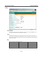
Video
Text on Video
Administrators can specify camera information by typing text into the Text on image box. The
text will appear on the frame above the image for reference.
Color
The Color setting depends on the connected camera. If the camera’s image is captured in color,
the administrator can decide that the image shown on VPort’s webpage is in color or B/W. The
“B/W” option can speed up the encoder. If the camera’s image is captured in B/W, the image will
only be shown in B/W.
Size
There are 5 options for selecting image sizes:
Video Size (unit: pixels)
Half
Half × 2
Standard
Standard × 2
Double
NTSC
176 ×
352 ×
352 ×
704 ×
704 ×
112
240
240
480
480
4-10
PAL
176 ×
352 ×
352 ×
704 ×
704 ×
112
288
288
576
576
VPort 2310 User’s Manual
NOTE
System Configuration
Half × 2 consumes the same file size and bandwidth as Half, but has the same resolution as
Standard. For this reason, the visual effect of Half × 2 is worse than Standard. Likewise,
Standard × 2 consumes the same file size and bandwidth as Standard, but has the same
resolution as Double. For this reason, the visual effect of Standard × 2 is worse than Double.
Modulation
There are 3 types of Modulation. Administrators can set the auto-detect condition during
initialization by selecting Auto, but can still set it manually by selecting NTSC or PAL.
Maximum Frame Rate
Administrators can set up the maximum frame rate of the video stream manually to save
bandwidth. You may choose from 8 frame rates: 1, 2, 3, 5, 10, 15, 20, 25, and 30. The maximum
frame rate is determined by the Video Size. For example, once the video size is set to double, the
maximum frame rate is only 10.
Video Size (unit: pixels)
Half
Half × 2
Standard
Standard × 2
Double
Maximum Frame Rate
30
30
30
30
10
Video Quality Control
Video Quality Control is used to optimize the bandwidth of the MPEG4 video stream. There are
2 modes for video quality control.
NOTE
1.
Fixed bit rate: the administrator can fix the bandwidth to tune the video quality and FPS
(frames per second) to the optimum combination. You may choose from 7 bandwidths: 64K,
128K, 256K, 384K, 512K, 768K, 1000K, and 1200K bps. The combination of image
quality and FPS is determined by the bandwidth. For example, the FPS is slow and the
quality is bad at 64 Kbps, and the quality is best at 1200 Kbps. But the FPS is about 10 due to
the limitation of VPort’s system resources.
2.
Fixed Quality: the administrator can set the image quality to one of 5 standards: Medium,
Standard, Good, Detailed, and Excellent. VPort will tune the bandwidth and FPS
automatically to the optimum combination.
The default video quality control setting is Fixed bit rate at 384 Kbps. At this bandwidth, the
image quality is good under most conditions if the FPS is near 30 and the video size is normal.
But the image quality, FPS, and bandwidth are influenced significantly by the network
throughput, system network bandwidth management, applications VPort runs (such as VMD),
how complicated the image is, and the performance of your PC or notebook at displaying
images. The administrator should take into consideration all of these variations when designing
the video over IP system, and when specifying the requirements for the video system.
4-11
VPort 2310 User’s Manual
System Configuration
Enable Motion Detection
Checkmark the □ Enable Motion Detection box to enable the VMD (Video Motion Detection)
function. To set up VMD, refer to the Configuration/Motion Detection page.
Flip and Mirror
Flip and Mirror are used to change what the image looks like on VPort’s homepage. Checkmark
the Flip box to flip the image about a vertical axis, and checkmark the Mirror box to flip the
image about a horizontal axis.
Image Setting
To adjust image settings for the best visual quality, click on Image Settings to open a motion
picture window. Four fields need to be configured: Brightness, Contrast, Hue, and Saturation.
Each field has eleven levels, ranging from -5 to +5. Click on preview at any time to see if the
settings are appropriate before clicking on Save. If the adjustment is not satisfactory, click on
restore to restore the original settings. When finished, click on Close to close the window. If the
configuration is changed without saving, the settings will be deleted the next time the system starts
up.
Save the settings
Click on the Save button to save the settings to the VPort. The message shown below will pop up,
informing you that If you change the modulation, the server will restart and you need to
reconnect [to] the server by reloading the web page. This means that the VPort will only restart
its system if you change the camera’s modulation manually. In addition, if are not using a fixed IP
address, or you find that the previous IP address no longer connects to the VPort, you will need to
run the installation process again to relocate the VPort’s IP address.
4-12
VPort 2310 User’s Manual
System Configuration
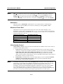
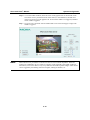
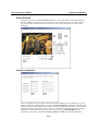
Motion Detection
Three areas can be selected for configuring VPort 2310’s VMD (video motion detection) function.
The VMD alarm will only be triggered when the VMD conditions in these 3 specific areas are met.
Each area can be fine tuned to fit the environment for different VMD conditions by setting
Sensitivity and image change Percentage.
1.
Sensitivity sets the measurable difference between two sequential images to indicate motion.
2.
Percentage sets the minimum size of the image whose motion will be detected. (E.g., if
Object size = 30%, then the system will only detect the motion of objects that occupy an area
larger than 30% of the total monitored area; the motion of objects with size less than 30% of
the monitored area will NOT be detected.)
How to Set up a VMD condition
Step 1: To enable VMD settings, go to the Configuration/Video page and checkmark the □
Enable Motion Detection box.
Step 2: Click the image. A VMD window will pop up. Right click the title bar of this window to
move the location of the VMD window, or drag the boarder to change the window size so
that it fits the desired VMD area.
Step 3: Use Window Name to assign a name to this VMD window (refer to the Trigger
Condition in the Configuration/Application page).
Step 4: Set up the Sensitivity and Percentage parameters by moving the percentage cursor.
Step 5: Click on the Save button to save the settings.
4-13
VPort 2310 User’s Manual
System Configuration
Step 6: To test the VMD condition, check the action of the graphics bar on the left side of the
save button. Wave your hand in front of the camera, in the VMD area, and then note
which color shows up in the graphics bar. Green means VMD is not triggered, and Red
means VMD is triggered.
Step 7: Users will see a red frame with the VMD window size in the homepage’s image if the
VMD is triggered.
NOTE
Motion detection is provided as a reference because it is environment-dependent. When the
settings are configured to be very sensitive to motion, some triggered events might actually be
false alarms, since in fact there is only a tiny difference between sequential images. False alarms
can be triggered by the flashing of florescent lights, shifting of shadows, etc.
4-14
VPort 2310 User’s Manual
System Configuration
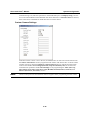
Application
Undefined
NOTE
After you set up the motion detection window, the Window name will be changed from
“Undefined” to the name you assigned it.
4-15
VPort 2310 User’s Manual
System Configuration
VPort 2310 Video Server provides 3 major applications.
1.
Weekly schedule: Administrators can set up the Application schedule by weekly day and
time.
2.
Event operation: Administrators can set Trigger Condition by selecting DI actions or VMD
options, and Trigger Action by selecting DO actions or Email/FTP options.
3.
Sequential Operation: Administrators can set the sequential snapshot mode to send the
snapshot by time interval.
Administrators can use combinations of options on the application web page to perform various
useful security applications.
To set up the applications that VPort 2310 Video Server provides, take the following steps to setup
the applications.
Step 1:
○All the time except for the above schedule
Choose the operation
period
○Weekly schedule
□Sun □Mon
snapshot begin
snapshot end
□Tue □Wed □Thu
00:00:00
00:00:00
□Fri □Sat
[hh:mm:ss]
[hh:mm:ss]
□ Event operation
□ Sequential mode
Step 3:
Step 3-1: setup the General
Snapshot every □ seconds
Set up the application’s
actions
Delay □ seconds before detecting
the next event
Take snapshot at □ seconds after
event
Step 2:
Choose the application
Step 3-2: setup the Trigger
Condition
□Input is high □Input is low
□Input is rising □Input is falling
Motion detected in:
□ Undefined □ Undefined □
Undefined
4-16
VPort 2310 User’s Manual
System Configuration
Step 3-3: setup the Trigger action
□Trigger output alarm while input
condition matched
□Trigger output alarm while
motion detected
□Upload snapshots while input
condition matched
□Upload snapshots while motion
detected
Step 4:
○Send snapshot by email
Choose the snapshot
images sending method
if you choose the
upload snapshot trigger
action or sequential
mode
○Send snapshot by FTP
□FTP put snapshots with date and time suffix
Step 5:
Click Save to enable the applications
Weekly schedule
The Weekly schedule is provided for daily security applications. Administrators can select any
weekday from Monday to Friday with the daily schedule set from 9 am to 6 pm when no one is
available to perform event checking. If the security system is installed in an office for which no
one is present on nights or weekends, administrators can still set the time period as above, from 9
am to 6 pm. However, remember to select All the time except for the above schedule to let the
program run during nights and weekends.
NOTE
Either “Weekly schedule” or “All the time except for the above schedule” must be selected, or
the applications described in the following sections will not work properly.
4-17
VPort 2310 User’s Manual
System Configuration
Event operation
Event operation is for setting security applications.
1.
2.
General
a.
Delay □ seconds before detecting the next event:
The administrator can set up the time interval (in seconds, from 0 to 999) between each
event’s trigger action.
b.
Take snapshot □ seconds after event:
The alarm message transmitted via FTP or Email is accompanied by snapshot images.
The administrator can set how much time (from 0 to 999 sec)to wait after an event is
triggered to take the snapshot.
Trigger Condition
There are 2 trigger conditions: Video Motion Detection (VMD) and Digital Input (DI).
a.
NOTE
VMD:
To set up the VMD trigger condition, the administrator should first configure the VMD
condition on the Configuration/Motion Detection page (refer to the “How to set up a
VMD condition” subsection earlier in this chapter), or click on the Motion Detection
link to link to the Motion Detection page. You are allowed to set up 1, 2, or 3 motion
detection windows. After you name a window, the name you selected will appear on the
Application page, below “detect motion in:”
VPort’s Network and Status LEDs can be used to determine if the VPort is transmitting and
receiving data over the network. Refer to Chapter 1 to see how to interpret the Network and
Status LEDs.
b.
3.
DI:
There are 4 Digit Input statuses, including Input is High, Input is Low, Input is
Rising, and Input is Falling. An edge trigger (e.g., Rising or Falling) is generally used
to detect the emerging signal from the external sensor.
Trigger Action
Once an event occurs, administrators can set up the trigger action after the event occurs
and/or send snapshots that are taken right at the moment. There are 2 trigger actions: Trigger
output alarm and Upload snapshot
a.
Trigger output alarm.
Administrators can set the trigger output alarm when the DI or Video Motion Detection
conditions are met. Check the box of the listed action to enable the triggered output
alarm.
b.
Upload snapshot. Administrators can set the upload snapshot action when the DI or
Video Motion Detection conditions are met.
4-18
VPort 2310 User’s Manual
NOTE
System Configuration
VPort 2310 Video Server will take 3 JPEG snapshot images: VPRE.JPG (pre-event), VTRG.JPG
(the moment of event) and VPOS.JPG (post-event) for the video channel when the trigger
condition is met. Three snapshots of the channel can also be downloaded via FTP or HTTP URL
(refer to the “Download Event-triggered Snapshots” section from Chapter 5 for more details).
c.
Reset output. When the digital output alarm is triggered, administrators can check this
Reset output option, and then click on Save to reset the digital output status.
Sequential Mode
With this feature, VPort 2310 Video Server can upload snapshots periodically to an external
E-mail or FTP server as a live video source. The interval can be set to anywhere from a tenth of a
second to several hours, with Snapshot every □ seconds. The external E-mail or FTP server
must be set up in the Network configuration page.
Send Snapshot by Email or FTP
Snapshots taken by either event operation or sequential mode, which are set in the Network
configuration page, can be sent by E-mail or FTP. If E-mail is chosen, the snapshots of the video
channel will be attached to the emails. If FTP is chosen, administrators can choose to add date and
time in the file name of the snapshots by checking FTP put snapshots with date and time suffix.
If the snapshots are used as the live video source, the date and time suffix can be eliminated to
update the same source file.
NOTE
In Sequential mode, the VPort will send out snapshots according to time interval settings. If
snapshot files are intended for quick updates, it is better to skip the date and time suffix, in which
case the file name will be video.jpg. If the snapshots are used for occasional monitoring,
suffixing with date and time can help administrators easily classify the snapshots.
NOTE
Compared to the FTP method, email will induce more delay, although email can notify users
more promptly.
Camera Control
VPort 2310 supports PTZ (PAN/TILT/ZOOM) motorized camera control via an RS-232 or
RS-485 COM port. Before setting up camera control, the administrator should first connect the
PTZ camera to the VPort.
4-19
VPort 2310 User’s Manual
System Configuration
Interface mode
The COM port supports 2 serial interfaces, although only one interface can be used at a time.
Depending on the interface used by the attached device, administrators must set the Interface
mode to either RS-232 or RS-485.
NOTE
The RS-232 interface is used via the DB9 COM port, and RS-485 interface is used via the GPIO.
These 2 interfaces cannot be used at the same time.
Baud rate (bps)
The administrator should set the baud rate to the baud rate specified by the PTZ camera’s serial
communication specs.
Select Camera driver
Administrators must select the correct PTZ model under PTZ driver options, since each PTZ
camera has its own protocols for the PTZ functions. Refer to Appendix B, Settings for Supported
PTZ Cameras, to see the PTZ cameras that Moxa VPort 2310 Video Server supports. If the
attached PTZ camera is not supported by the VPort, administrators can select Custom Camera to
enter the proprietary commands for pan, tilt, zoom, and focus control.
4-20
VPort 2310 User’s Manual
System Configuration
Preset Position
Administrators can use the Preset Position function to set up the behavior of the PTZ camera in
advance, and then users with the camera control privilege can directly move the camera’s lens to
the preset position without the need to control the pan, tilt, and zoom buttons on VPort 2310’s
homepage.
Custom commands
VPort 2310 Video Server provides 5 custom commands in addition to the general pan, tilt, zoom,
and preset functions. Administrators can click on Custom Command to configure, and refer to the
manual enclosed with the attached PTZ camera to set up frequently-used functions. The Command
should be entered in ASCII format. The VPort will translate the commands into binary code and
send them out through the serial port. For instance, a text string of 8101ABCDEF will be
translated into five bytes of hexadecimal 81, 01, AB, CD, and EF. The maximum length of a
4-21
VPort 2310 User’s Manual
System Configuration
command string is 60, which is equivalent to 30 hexadecimal bytes. The Display string is for the
text on the command buttons and should be less than 8 characters. If Custom Camera is selected,
there will be more commands for PTZF that relate to custom camera.
Custom Camera Settings
If the PTZ camera’s driver is not in the list, the administrator can select the custom camera from
the Select Camera driver menu to program the PTZ camera with ASCII code. A custom camera
window will pop up when the Setting for Custom Camera button is clicked. Input the ASCII
code into this window. Port Settings (Data bits, Stop bits and Parity bits) are for the serial
communication parameters and Control Settings are for programming the TILT (Move Up,
Move Down), PAN (Move Left, Move right), HOME, ZOOM (Zoom in, Zoom out) and
FOCUS (Focus near, Focus Far) actions.
NOTE
Get the control protocols from the PTZ camera’s supplier before programming the PTZ camera.
4-22
VPort 2310 User’s Manual
System Configuration
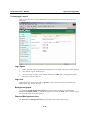
Homepage Layout
VPort 2310 Video Server allows administrators to customize the layout of the Video Server’s
homepage.
Logo figure
1.
Select the blank option to hide the logo that appears in the upper-left corner of the homepage.
2.
The “default” logo is the Moxa logo.
3.
An external logo or image can be used by selecting the URL option, and typing the url for
the image in the text input box.
Logo link
Administrators set up the Logo with a Logo link, so that visitors are directed to another web
address when they click on the logo.
Background graph
As with Logo graph, Background graph gives administrators the ability to customize the
background as blank, default, or an external image, by selecting the URL option, and then typing
the url for the image in the text input box.
Font and Background color
The Font color and Background color can be chosen from sixteen custom colors.
4-23
VPort 2310 User’s Manual
NOTE
System Configuration
The Background color option is active only when Background graph is set as blank.
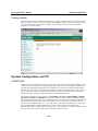
View log file
The system log contains useful information, including current system configuration and activity
history with timestamp for tracking.
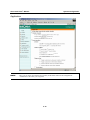
View parameters
Clicking on “View parameters” allows you to view all system parameters, which are listed by
category. The content is the same as VPort 2310 Video Server’s CONFIG.INI file.
4-24
VPort 2310 User’s Manual
System Configuration
Factory default
This function is used to restore the Video Server to its factory default settings, so that any changes
that were made previously will be lost. After clicking OK, the system will restart. Note that it will
take some time for the restore action to finish. You will need to run the software installation
program to set up the network.
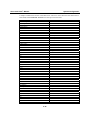
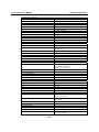
System Configuration via FTP
CONFIG.INI
FTP can be used to configure VPort 2310 Video Server much more quickly than configuring from
web browser, particularly when configuring multiple Video Servers. To configure a Video Server
via FTP, first download the parameter file, CONFIG.INI, customize each field, and then upload
the file to the Video Server to install the new settings. To log into the FTP daemon, enter “root” as
the user name, and use the same password used when connecting to the Web server. The MAC
address (no dashes, all upper case) of FTP Server is the default password.
The CONFIG.INI file has eight categories: [SYSTEM], [LAYOUT], [NETWORK], [VIDEO],
[SERIAL], [ALERT], and [DEMO]. The category names in square brackets should be in upper
case. The item names in angle braces should be in lower case. Some items related to disable/enable
should use the keywords “YES”/“NO”. The number zero (0) entered in <user name> and <user
password> is for administrators, i.e. “root”. Video Server will restart automatically as soon as the
file is uploaded and accepted. If administrators want to cancel the reboot procedure after
transferring config.ini via FTP, then set the first item, <reset system>, to NO. But it will take effect
only once, and show YES in the download config.ini file the next time.
4-25
VPort 2310 User’s Manual
System Configuration
A sample CONFIG.INI is shown in the table below. The text in italics describes the characteristics
of the field, and the bold italic characters are the options for the field.
Video Server Initial Configuration file
[SYSTEM]
<reset system>
YES
<host name>
VPort 2310 Video Server
<serial number>
0002D1005689
<software version>
VS3102-Moxa-0200t
<current date>
2004/11/01
<current time>
12:34:56
<time zone>
0
<user name>
(0)root
(1)
(2)
(3)
(4)
(5)
(6)
(7)
(8)
(9)
(10)
(11)
(12)
(13)
(14)
(15)
(16)
(17)
(18)
(19)
(20)
(21) Demo
<user password>
(0)0002D1000972
(1)
(2)
(3)
(4)
(5)
(6)
(7)
(8)
4-26
or NO
string with maximum of 40 characters
read-only
read-only
read-only
read-only
from 12 to –12, GMT + Value
read-only
string with maximum of 16 characters
the rest are the same as above
string with maximum of 16 characters
the rest are the same as above
VPort 2310 User’s Manual
System Configuration
(9)
(10)
(11)
(12)
(13)
(14)
(15)
(16)
(17)
(18)
(19)
(20)
(21)
<language>
en
<ptzenabled>
0
<NTP Update Interval>
0
Current Language, read-only
read-only
0-Hourly, 1-daily, 2-weekly, 3-monthly
[LAYOUT]
<font color>
1
<background color>
0
<logo type>
1
<background type>
1
<logo source>
http://
<background source>
http://
<logo link>
http://
0-black, 1-white, 2-green, 3-maroon, 4olive, 5-navy, 6-purple, 7-gray, 8-yellow,
9-lime, 10-aqua, 11-fuchsia, 12-silver,
13-red, 14-blue, 15-teal,
default image, or 0 for blank, or 2 from URL
default image, or 0 for blank, or 2 from URL
URL of logo type 2, maximum of 80 characters
URL of logo type 2, maximum of 80 characters
reference link of logo, max. of 80 characters
<com speedlink name>
(0)
(1)
(2)
(3)
(4)
Name of custom PTZ commands
string with maximum of 8 characters
string with maximum of 8 characters
string with maximum of 8 characters
string with maximum of 8 characters
string with maximum of 8 characters
[NETWORK]
<install enabled>
YES
<ppp enabled>
YES
<ethernet address>
00-02-D1-00-56-89
<host ip>
reset IP whenever system boots or NO
obsolete
read-only
4-27
VPort 2310 User’s Manual
System Configuration
192.168.0.207
<subnet mask>
255.255.255.0
<gateway ip>
0.0.0.0
<primary name server>
0.0.0.0
<secondary name server>
0.0.0.0
<ntp enabled>
NO
<network timing server>
standard IP format
standard IP format
standard IP format
standard IP format
standard IP format
or YES
IP address or domain name
<smtp mail server>
IP address or domain name
<SMTP account name 1>
string of maximum 63 characters
<SMTP password 1>
string of maximum 15 characters
<mail recipient address>
string with maximum of 80 characters
<mail return address>
VPort 2310 Video Server
<backup smtp mail server>
string with maximum of 80 characters
IP address or domain name
<SMTP account name 2>
string of maximum 63 characters
<SMTP password 2>
string of maximum 15 characters
<backup mail recipient address>
string with maximum of 80 characters
<local ftp port>
21
<ftp server>
or 1024 to 65535
IP address or domain name
<ftp port>
21
<ftp username>
or 1024 to 65535
string with maximum of 16 characters
<ftp password>
string with maximum of 16 characters
<ftp init path>
string with maximum of 40 characters
<ftp passive>
NO
<backup ftp server>
or YES
IP address or domain name
<backup ftp port>
21
<backup ftp username>
or 1024 to 65535
string with maximum of 14 characters
4-28
VPort 2310 User’s Manual
System Configuration
<backup ftp password>
string with maximum of 14 characters
<backup ftp init path>
string with maximum of 40 characters
<backup ftp passive>
NO
<http server port>
80
<control channel port>
5001
<audio channel port>
5002
<video channel port>
5003
or YES
or 1024 to 65535
1024 to 65535
1024 to 65535
1024 to 65535
<low bandwidth environment>
0
or YES, Improve audio quality in low bandwidth
environment
<mute>
0
or YES
[DDNS]
<enable>
0
<provider>
0
1-DynDNS.org(Dyanamic),
2-DynDNS.org(Custom)
3-TZO.com, 4-dhs.org
<hostname>
IP address or domain name
<username/email>
string of maximum 63 characters
<password/key>
string of maximum 21 characters
[UPNP]
<enable>
Yes
or NO
[VIDEO]
<camera modulation>
AUTO
or MANUAL. NTSC or PAL will be ignored
when set to AUTO
or PAL, ignored when set to AUTO but can be
notification
NTSC
<caption text>
string of maximum 16 characters
<colored video>
YES
<video quality>
8
or NO for monochrome
4-execllect, 6-good, 8-normal,
10-rough, 12-bad
4-29
VPort 2310 User’s Manual
System Configuration
<brightness>
0
<contrast>
0
<hue>
0
<saturation>
0
<rate control>
YES
<bit rate>
384K
between 5 and –5
between 5 and –5
between 5 and –5
between 5 and –5
or NO
values:64k, 128k, 256k, 384k, 512k, 768k,
1000k, 1200k
<frame rate>
30
<video size>
1
values:1, 2, 3, 5, 10, 15, 20, 25, 30
Half, 2-Halfx2, 3-Normal, 4-Normalx2,
5-Double
<motion detect enabled>
YES
<flip>
NO
<mirror>
NO
or NO
or YES
or YES
[SERIAL]
<auto detect camera>
NO
<data bits>
0
<stop bits>
0
<parity bits>
0
<baud rate>
0
<ccd model>
0
or YES
None, 1 for Odd, 2 for Even
None, 1 for Custom Camera, 2 for Sony VISCA,
3 for Canon VC-C1, 4 for Canon VC-C3, 5 for
Canon VC-C4, 6 for DynaDome, 7 for Pelco D,
8 for LiLin
<uart mode>
RS232
<speedlink commands>
(0)
(1)
(2)
(3)
(4)
<custom ccd commands>
HOME
or RS485
string of maximum 60 characters
string of maximum 60 characters
string of maximum 60 characters
string of maximum 60 characters
string of maximum 60characters
string with maximum of 60 characters
4-30
VPort 2310 User’s Manual
System Configuration
UP
string with maximum of 60 characters
DOWN
string with maximum of 60 characters
LEFT
string with maximum of 60 characters
RIGHT
string with maximum of 60 characters
TELESCOPE
string with maximum of 60 characters
WIDE
string with maximum of 60 characters
NEAR
string with maximum of 60 characters
FAR
string with maximum of 60 characters
[ALERT]
<application mode >
0
disabled, 1 for Sequential, 10 for motion
detection event, 12 for DI event
<upload method>
0
<file with time suffix>
YES
<seconds to snapshot after event>
0
<seconds delay before next event>
0
<seconds to snapshot periodically>
0
<time to start snapshot>
00:00:00
<time to stop snapshot>
00:00:00
FTP, 1 for email
or NO
0 ~ 999
0 ~ 999
0 ~ 999
24 hours format
24 hours format
[FEATURE]
<event>
1
4-31
VPort 2310 User’s Manual
System Configuration
System Configuration Via Telnet
Telnet Commands
Video Server has a Telnet daemon that allows administrators to access some seldom used
functions. Using any general terminal program to connect to Video Server will prompt the user for
a password. The Username is not requested since only administrators can access the Telnet
daemon. The password is the same as that used for web access. After logging in, type “help” for
the command list. If “debug” or “dinote” is not executed, Telnet will disconnect automatically
after being idle for 1 minute.
System core debugging
General activities are recorded into SYSTEM.LOG continuously, but information about abnormal
status is not recorded. Administrators can type the “debug” command to examine in-depth core
debugging information. This causes Video Server to start dumping the detailed debugging
information while the system is running. This is useful for examining if any errors have occurred
when the system operates abnormally. The stored information will be cleared automatically after
the dump. Video Server will continue to dump new messages unless the connection is broken. If
Telnet is not connected, messages will be stored until administrators re-login.
Monitoring changes to digital input status
Typing “dinote” will make Video Server send the current status of all digital inputs. After that,
Video Server will continuously monitor DI status and send messages only when the state has
changed. For example, after typing “dinote” the terminal will display
DI=L
and after DI1 changes to H, the terminal will display
DI=H
Stop information dumping
Typing “stop” will halt the dumping of debug information and the digital input status.
Query status of digital inputs
Typing “diquery” will display the status of all digital inputs once.
Set digital outputs
To set digital output to connect NO with COMMON, type “DO=L”.
To set digital output to connect NC with COMMON, type “DO=H”.
Erase snapshots stored in Flash memory
Typing “erase image” will clear all snapshots saved in Flash memory.
Skip installation at next boot
Typing “lock” will inform Video Server to lock the current network settings. You won’t need to
go through the installation procedure the next time the Video Server boots up.
4-32
VPort 2310 User’s Manual
System Configuration
Erase logo and graphic buttons
Typing “erase graph” will clear all images used on the homepage. If no new images are uploaded,
the system will switch to text mode and use default images instead.
Reset network
Typing “unlock” will cause Video Server to wait for the installation procedure the next time it
boots up.
Restore factory default settings
Typing “clear” will make Video Server restore factory settings but not restart. To validate new
settings, type “reset” to make the system restart.
Reset system
Typing “reset” will make Video Server perform a software reset.
4-33
5
Chapter 5
Advanced Applications
This chapter will introduce more advanced applications.
The following topics are covered in this chapter:
Capturing Up-to-date Still Images
¾ Getting snapshot via URL
¾ Getting snapshot via FTP
Video Embedded in Customers’ Homepage
Download Event-triggered Snapshots
¾ Getting triggered snapshots via URL
¾ Getting triggered snapshots via FTP
Customizing Homepage Graphics
URL Commands for DI/DO & Camera’s Actions Setting
¾ Query status of digital inputs
¾ Drive digital outputs
¾ Moving motorized camera in PTZ direction
¾ Recalling camera position
¾ Transparent Remote Serial Driver
¾ Sending commands to devices attached to the COM port
URL Commands for System Maintenance
¾ Download System Log via FTP
¾ Restart System via URL
¾ Restore Factory Default Settings via URL
VPort 2310 User’s Manual
Advanced Applications
Capturing Up-to-date Still Images
Getting snapshot via URL
Administrators and users can use a specific URL to capture the current still image.
URL
http://<IP of Video Server>/cgi-bin/video.jpg
Getting snapshot via FTP
Administrators and users can log in to the Video Server FTP daemon to download the refreshed
JPEG image named video.jpg. The user name and password are the same as for web access. The
zero file size in the file directory means it is captured by request.
Video Embedded in Customers’ Homepage
In addition to the URL, some scripts should be added to download a plug-in for video images. The
following example simply displays title text and a real-time video window in Internet Explorer or
Netscape. The user name and password should be configured in advance. Those who are familiar
with HTML can easily add more components or rewrite the code to create a more vivid and useful
homepage.
<tr><td height=5> </td></tr>
<tr><td align=center>
<script language="JavaScript">
<!-if ((navigator.appName == "Microsoft Internet
Explorer")&&(navigator.platform != "MacPPC"))
{
document.write("<OBJECT ID=\"VAMCtrl\" WIDTH=362 HEIGHT=306");
document.write("
CLASSID=CLSID:A93B47FD-9BF6-4DA8-97FC-9270B9D64A6C");
document.write("
CODEBASE=\"/plugin/h263ctrl.cab#version=1,8,0,5\">");
document.write("<PARAM NAME=\"DigitalZoomEdit\" VALUE=\"true\">");
document.write("<PARAM NAME=\"EnableVolumeControl\"
VALUE=\"false\">");
document.write("<PARAM NAME=\"Deblocking\" VALUE=\"true\">");
document.write("<PARAM NAME=\"Url\"
VALUE=\"http://username:[email protected]/cgi-bin/video.vam\">");
document.write("<PARAM NAME=\"VSize\" VALUE=\"SIF\">");
document.write("<PARAM NAME=\"Language\" VALUE=\"EN\">");
document.write("</OBJECT>");
}
//-->
</script>
</td></tr>
NOTE
The camera's image will not be visible when using IE6.0 Security Package Update (MS04-004),
since it will block VPort’s username and password on a customized homepage. You may need to
disable VPort password protection, or check the patch description of IE (No. 832894) to solve
this problem.
5-2
VPort 2310 User’s Manual
Advanced Applications
Download Event-triggered Snapshots
There are three video image files for the video channel of three stages: pre-alarm, the moment
when triggered, and post-alarm. Only the snapshots captured by the last event are preserved.
Administrator and users can use FTP or URL to get the saved snapshots. They can also be browsed
from the application page under system configuration.
Getting triggered snapshots via URL
/cgi-bin/snapshot.jpg?file=<value>
Video channel
Value
Snapshot stage
snapshot before event
Pre
snapshot upon event
trg
snapshot after event
pos
Getting triggered snapshots via FTP
File name
Video
Pre-alarm
vpre.jpg
Upon alarm
vtrg.jpg
Post-alarm
vpos.jpg
Customizing Homepage Graphics
The small icon before each link can be changed by the Administrator. There are three types of
logos and backgrounds: blank, default, and other URL. The default method will use the image
stored in the Flash memory. The administrator may change the default logo, background image,
and button images by uploading customized ones. The following table shows the referenced file
names and size limitations.
Object
Logo
Background
Link icon
File name
logo.gif
back.gif
btn_text.gif
Usage via FTP is illustrated below.
5-3
Maximal size
Logo and background share 8000 bytes
Logo and background share 8000 bytes
2000 bytes
VPort 2310 User’s Manual
Advanced Applications
URL Commands for DI/DO & Camera’s Actions Setting
Query status of digital inputs
/setup/getdi.cgi
Video Server will return status of four digital inputs in one line.
Drive digital outputs
/setup/setdo.cgi?do=<state>
Where state is H, L. H means NC connected with COMMON and L means NO connected with
COMMON.
For example, http://192.168.0.201/setup/setdo.cgi?do=h will command the Video Server, with IP
address of 192.168.0.201, to set digital output to connect to NC with COMMON.
Moving motorized camera in PTZ direction
<Direction>:
up, left, right, down, home
<Vision>:
wide, tele, near, far, auto
<Command>:
1, 2, 3, 4, 5
/cgi-bin/camctrl.cgi?Move=<direction>&zoom=<vision>&cust=<command>
Param
move
Value
up
down
left
right
home
wide
tele
near
far
auto
-5 to 5
-5 to 5
zoom
focus
panspeed
tiltspeed
Description
Tilt up
Tilt down
Pan left
Pan right
Return to home position
Zoom in
Zoom out
Focus near
Focus far
Automatic focus
Recalling camera position
/cgi-bin/recall.cgi?recall=<position>
<position>:
the text string of a location that is preset in system configuration.
Refer to Camera preset configuration URL for preset function.
Transparent Remote Serial Driver
Video Server provides highly customized control support for third-party serial interface devices
(other than PTZ cameras). This means that in addition to setting up a custom camera with PAN/
TILT/ ZOOM/ FOCUS commands, users may utilize this mode and introduce a customized
homepage to transmit arbitrary user-defined commands from user-side to Video Server. The
third-party device connected to the serial port of Video Server will receive the same command sent
5-4
VPort 2310 User’s Manual
Advanced Applications
by the originator. The user only needs to attach the command in ASCII format after the special
URL. The Video Server will parse the commands and translate into binary code to send out.
Sending commands to devices attached to the COM port
This URL applies to the attached serial port device including supported PTZ cameras or
non-supported custom camera. Note that the serial port settings of custom cameras must be
correctly defined in advance.
/cgi-bin/senddata.cgi?data=123456, ABCDEF&flush=yes&wait=1000&read=6
This hyperlink will inform Video Server to send out binary format commands to the COM with
“0x12, 0x34, 0x56” followed by “0xAB, 0xCD, 0xEF”. Each comma separates the commands by
200 milliseconds. “Flush=yes” means the receive data buffer of the COM port must be cleared
before read. Then read 6 bytes after waiting for 1000 milliseconds. The read data can be up to 128
bytes and will return as ASCII coded hexadecimal value, e.g., 0x41, 0x42, 0x43 read from COM
port will show in returned homepage as 414243 instead of ABC.
URL Commands for System Maintenance
Download System Log via FTP
Besides viewing the system log from the web page, administrators can download the system log
file, SYSTEM.LOG, via FTP. To log into the FTP daemon, enter “root” as the user name and the
same administrator’s password used in Web access.
Restart System via URL
/setup/reset.cgi
Restart Video Server without warning.
Restore Factory Default Settings via URL
/setup/restore.cgi
Video Server will automatically restart after restoring factory default configurations.
5-5
6
Chapter 6
Upgrading System Firmware
Customers can check the appropriate product page on Moxa’s website to download the latest
firmware. Only administrators can upgrade the system firmware of Video Server.
The following topics are covered in this chapter:
Using Upgrade Wizard to Upgrade Firmware
Using FTP to Upgrade Firmware
VPort 2310 User’s Manual
Upgrading System Firmware
Using Upgrade Wizard to Upgrade Firmware
Step 1: Run the Upgrade Wizard (.exe) included in the product CD.
Step 2: Type the web address of the Video Server whose firmware you want to upgrade, and then
type the administrator password. Click on Next to proceed.
Step 3: The program will detect the Video Server.
If the password is incorrect, a window will appear asking you to recheck the FTP port and
password.
Step 4: After the Video Server has been detected, select the firmware (Flash.bin) to process the
upgrade.
Step 5: Wait a few seconds for the upgrade process to finish.
Step 6: The following message appears once the firmware has been upgraded successfully.
6-2
VPort 2310 User’s Manual
NOTE
Upgrading System Firmware
The power supply of VPort 2310 Video Server should not be turned off when the Upgrade
Wizard is upgrading the firmware. Otherwise, the firmware upgrade will fail, and you will need
to return the video server to Moxa for repair.
Using FTP to Upgrade Firmware
Step 1: Use the FTP program and change the working directory to the local folder where
FLASH.BIN resides.
Step 2: Connect to Video Server with user name “root” and password.
Step 3: Use the PUT command to upload FLASH.BIN to the Video Server. The file size is almost
1.5 MB. It will take approximately 2 seconds over a local network, but the actual time
will depend on the status of the user’s network.
Step 4: After the upload is complete, close the connection.
If the received FLASH.BIN is checked without error, the Video Server will update the software to
the Flash memory and restart automatically. When the Video Server starts writing the firmware,
both status LED indicators will remain lit until the system restarts (this takes about 30 to 40
seconds). You must keep the power stable during the update process. After the system restarts, the
Video Server may need to be re-installed, depending on whether the Reset network at next boot
option is enabled or not. After the Video Server boots up, reload the web page in the browser.
NOTE
We strongly recommend that you use the upgrade wizard to upgrade the firmware for a
Microsoft Operating System, since if the power fails during the software upgrade, the program in
the memory of Video Server may be destroyed permanently. If Video Server cannot restart
properly, ask the dealer for technical service.
NOTE
For customizing your VPort’s settings, we strongly recommend that you download config.ini via
FTP before you upgrade the firmware. The risk is that once the firmware has been upgraded, the
settings in config.ini might be restored to the initial settings. For this reason, after the firmware is
upgraded, you need to upload the config.ini and overwrite the one existing in your VPort. By
doing this, you won’t need to re-configure your VPort’s.
6-3
7
Chapter 7
Troubleshooting
This chapter describes some problems that might occur during installation or operation, and
provides the basic solutions to those problems.
The following topics are covered in this chapter:
Power On Self Test (POST)
Frequently Asked Questions
VPort 2310 User’s Manual
Troubleshooting
Power on Self Test (POST)
After the power has been turned on, Video Server will perform a self-diagnostic to detect any
possible hardware defects. The status LEDs will blink during the POST, and will keep blinking
until the POST has finished, or a fatal error is detected. If either status LED indicator is dim to
start off with, the LED may be broken.
When certain fatal errors occur, LED2 and LED3 blink in a particular way to indicate the type of
failure, as described in the following table.
LED pattern after POST
Failed function
LED2 and LED3 blink at same U32(SAA7113)
time
LED2 ON and LED3 OFF
U1(TM1300)
LED2 OFF and LED3 ON
U6(RTL8139C)
LED2 ON and LED3 ON
U6(RTL8139C), U7, U8
LED2 blink and LED3 ON
U22(M5823)
LED2 ON and LED3 blink
U19(16C1550CJ), P2
Troubleshooting
Video decoder
PCI bridge of TM1300
Ethernet controller
Ethernet interface*
Real-time clock
COM interface
NOTE
Ethernet interface failure includes not only on-board components, but also the Ethernet cable and
the devices at the opposite end.
NOTE
To reduce the chance of system failures caused by Administrator error, always read the related
sections in this user’s manual to prevent unexpected errors caused by “wild-guess
configuration.”
Frequently Asked Questions
Q: What if I forget my password?
A: Every access to Video Server needs authentication. If you are one of the managed users, you
need to ask the administrator for the password. If you are the administrator, there is no way to
recover the root password. The only way to regain access to Video Server is to utilize the
default setting button on the rear panel to restore the factory settings and reinstall it (see p. 1-7
for details).
Q: Why can’t I see video from the Video Server after it has been authenticated?
A: There are many possible scenarios:
1.
If you have just installed the Video Server and are unable to see the video, check the
video modulation on the Configuration page.
2.
If the Video Server is installed correctly and you are accessing the Video Server for the
first time using Internet Explorer, adjust the security level of Internet Explorer to allow
installation of plug-ins.
3.
If the problem still exists, the number of users accessing the Video Server at the same
time may exceed the maximum that the system allows.
7-2
VPort 2310 User’s Manual
Troubleshooting
Q: What is the plug-in for?
A: The plug-in provided by Video Server is used to display motion pictures on versions of Internet
Explorer that do not support server push technology. If your system does not allow installation
of any plug-in software, the security level of the web browser may need to be lowered. It is
recommended that you consult the network supervisor in your office before adjusting the
security level.
Q: Why is the timestamp different from the system time of my PC or notebook?
A: The timestamp is based on the system time of Video Server. It is maintained by an internal
real-time clock, and automatically synchronizes with the time server if Video Server is
connected to the Internet and the function is enabled. Differences of several hours may result
from the time zone setting.
Q: Why doesn’t the image refresh regularly?
A: This may be due to the time taken for storing snapshots into memory when events occur.
Q. How does the Video Server detect the supported PTZ cameras automatically?
A. If a camera is not detected, the Video Server will monitor the CTS of the camera control cable
continuously. As long as the CTS is detected, the Video Server will try to handshake with
supported cameras until a supported camera is found. Camera detection will cease once a PTZ
camera is recognized.
Q: How many users are allowed to access Video Server at the same time?
A: Basically, there is no limitation. However the video quality also depends on the network
bandwidth. To achieve the best effect, the Video Server will allow 20 users to be connected. It
is recommended to build another web server to host a large quantity of users by retrieving
images from the Video Server periodically.
Q: What is Video Server’s video rate?
A: The MPEG4 codec can process 30 frames per second internally. However the total
performance is subject to many coefficients as follows:
1.
Network throughput.
2.
Bandwidth share.
3.
Number of users.
4.
The complicated objects in view results in larger image file.
5.
The level of your PC or notebook which is responsible for displaying images.
In general, the transfer rate for a general local network environment can achieve over 200
kilobytes per second and approximately 10 to 20 pictures of a normal environment per second.
7-3
VPort 2310 User’s Manual
Troubleshooting
Q: How can I keep the Video Server as private as possible?
A: The Video Server is designed for surveillance purposes and has many flexible interfaces. The
user authentication and special confirmation in installation can keep the Video Server from
unauthorized access. You may also change the HTTP port to a non-public number. You can
check the system log to examine any abnormal activities and trace the origins.
Q: I have a PTZ camera that is not on the support list. How can I control it?
A: Video Server provides a custom camera command interface to control cameras that are not
supported. The details are described in this manual. Be sure that the COM port settings are
applied to the camera specifications. The camera control cable included is shown in the
package contents. Prepare your own cable if necessary. The general PTZ command is
composed of one start command and one stop command. When editing both commands in the
edit box of the configuration page, use comma(s) to separate commands. Each comma
represents 200 milliseconds. If the user has some serial control device other than the PTZ
camera, the special URL is provided to send the desired commands. For quick access, integrate
the URL to another homepage on your own web server.
Q: How fast will Video Server check the status of digital inputs?
A: The Video Server will check input status in less than half a second. However, to avoid
repeatedly checking conditions too often and to allow the devices connected to digital outputs
to function properly, the Video Server will delay 3 seconds by default after each condition
matches. Users may change it according to specific applications. During this period, any
condition will be ignored.
Q: Why can I not access the Video Server when I set up some options in the application?
A: When the Video Server is triggered by events; snapshots will take more time to write to
memory. If the events occur too often, the system will always be busy storing images. It is
recommended to use sequential mode or an external recorder program to record motion
pictures if the event is frequent. If you prefer to retrieve images via FTP, the value could be
smaller since FTP responds quicker than the Web does. Once the system is too busy to
configure, use the restore factory default and reset button to save the system.
Q: I tried connecting my black-and-white and color cameras with the Video Server but the image
is not good.
A: Although the Video Server allows users to choose color or black-and-white images for each
camera, hybrid camera types may increase video processing time and reduce system
performance.
Q: The image is not clear enough. Is anything broken?
A: The lens can be focused by rotating the outer ring. Rotate it clockwise or counter-clockwise to
focus near or far.
7-4
A
Appendix A
URL Commands of Video Server
Video Server can be easily integrated with existing websites or web control applications using
convenient URLs. This section lists the commands in URL format corresponding to the basic
functions of Video Server. Some RFC standards related to HTML may be a good reference for
implementation of the customized homepage.
Page URL
The configuration page has a frame layout that includes an option list frame and an option page
frame. Except for the configuration page, the Reference URLs shown below link just to the option
page frame. Some pages, such as image quality settings and preset settings, open in a new browser
window. These URLs can be accessed only by administrators.
Homepage name
Referenced URL
Client setting page
/client.html
configuration page
/setup/config.html
system option
/setup/system.html
security option
/setup/security.html
network option
/setup/network.html
video option
/setup/video.html
image quality option
/setup/image.html
camera control
/setup/camera.html
preset PTZ camera
/setup/preset.html
custom command setting
/setup/command.html
custom camera setting
/setup/custom.html
application option
/setup/app.html
homepage layout option
/setup/layout.html
system log
/setup/logfile.html
system parameters
/setup/parafile.html
set factory default
/setup/factory.html
VPort 2310 User’s Manual
URL Commands of Video Server
System Resource URL
Some images are used on the homepage when the homepage layout is in image mode.
Administrators may use the following links to show the images saved on Video Server on another
page. To change the logo or the background images referenced by the URL, refer to the homepage
layout section under configuration.
Resource name
Reference URL
system logo image
/pic/logo.gif
background image
/pic /back.gif
icon image for link indicator
/pic /btn_text.gif
General Format of Command URL
Every configuration can be set through URL with POST method by Administrator only.
<General format>
URL [? [Name=value][&name=value]……]
<Method>
POST
<Authorized user>
Root
System Configuration URL
URL:
Name
host
method
date
time
ntp
zone
/setup/system.cgi
Value
<text string shorter than 15 characters>
keep
auto
manu
<yy/mm/dd>
<hh:mm:ss>
<domain name or IP address>
-12 ~ 12
Description
system name
keep date and time unchanged
use NTP server to synchronize
directly adjust date and time
year, month and date separated by slash
hour, minute and second separated by colon
NTP server
time zone, 8 means GMT +8:00
Security configuration URL
URL:
Name
rootpass
username
userpass
deluser
/setup/security.cgi
Value
<text string shorter than 15 characters>
<text string shorter than 15 characters>
<text string shorter than 15 characters>
<text string shorter than 15 characters>
A-2
Description
change root password
add new user
new user's password
existing user name
VPort 2310 User’s Manual
URL Commands of Video Server
Network configuration URL
URL:
/setup/network.cgi
Name
reset
Value
YES
NO
ip
<IP address>
subnet
<IP address>
router
<IP address>w
domain
<text string shorter than 40 characters>
dns1
<IP address>
dns2
<IP address>
smtp1
<domain name or IP address>
mailto1
<text string shorter than 80 characters>
smtp1Usr <text string shorter than 39 characters>
smtp1pass <text string shorter than 39 characters>
smtp2
<domain name or IP address>
Smtp2Usr <text string shorter than 39 characters>
Smtp2pass <text string shorter than 39 characters>
mailto2
<text string shorter than 80 characters>
return
<text string shorter than 80 characters>
http
<number less than 65535>
controlport <number less than 65535>
videoport
<number less than 65535>
audioport
<number less than 65535>
lowband
yes
no
mute
yes
no
ftp1
<domain name or IP address>
ftpuser1
<text string shorter than 15 characters>
ftppass1
<text string shorter than 15 characters>
ftpfolder1 <text string shorter than 40 characters>
ftp2
<domain name or IP address>
ftpuser2
<text string shorter than 15 characters>
ftppass2
<text string shorter than 15 characters>
ftpfolder2 <text string shorter than 40 characters>
A-3
Description
enable installation at next boot
disable installation at next boot
Video Server's IP address
subnet mask
default gateway
domain name of Video Server
primary DNS server
secondary DNS server
primary SMTP server
mail recipient address
Account name of SMTP1
Password of account in SMTP1
secondary SMTP server
Account name of SMTP2
Password of account in SMTP2
mail recipient address
return address
HTTP port
Control Channel port
Video Channel port
Audio Channel port
enable the low bandwidth environment
disable the low bandwidth environment
Enable audio streaming
disable audio streaming
primary FTP server
user name for primary FTP server
password for primary FTP server
upload folder in primary FTP server
secondary FTP server
user name for secondary FTP server
password for secondary FTP server
upload folder in secondary FTP server
VPort 2310 User’s Manual
URL Commands of Video Server
Video configuration URL
URL:
/setup/video.cgi
Name
text
Value
Description
<text string shorter than 15 characters> enclose caption
color
B/W
<other than B/W>
1
2
3
4
5
fixb
<other than fixb>
1
2
3
4
5
64000
128000
256000
384000
512000
768000
1000000
1200000
Auto
NTSC
<other than above>
1
2
3
5
10
15
20
25
30
size
quality
quan
bitrate
mode
frame
enablemd
flip
mirror
set encoder to monochrome
set encoder to color
half
half x 2
normal
Normal x 2
double
fix bit rate
fix quantization
lowest quality of video
lower quality of video
normal quality of video
higher quality of video
highest quality of video
set bit rate to 64K bps
set bit rate to 128K bps
set bit rate to 256K bps
set bit rate to 384K bps
set bit rate to 512K bps
set bit rate to 768K bps
set bit rate to 1000K bps
set bit rate to 1200K bps
let Video Server detect video modulation
set directly to NTSC type
set directly to PAL type
set maximum frame rate to 1 fps
set maximum frame rate to 2 fps
set maximum frame rate to 3 fps
set maximum frame rate to 5 fps
set maximum frame rate to 10 fps
set maximum frame rate to 15 fps
set maximum frame rate to 20 fps
set maximum frame rate to 25 fps
set maximum frame rate to 30 fps(NTSC
only)
enable motion detection
disable motion detection
flip image
normal image
mirror image
normal image
yes
<other than yes>
yes
<other than yes>
yes
<other than yes>
A-4
VPort 2310 User’s Manual
URL Commands of Video Server
Image quality configuration URL
URL:
/setup/image.cgi
Name
brightness
contrast
hue
saturation
preview
restore
save
Value
<-5 ~ 5>
<-5 ~ 5>
<-5 ~ 5>
<-5 ~ 5>
<not required>
<not required>
<not required>
Description
adjust brightness of image
adjust contrast of image
adjust hue of image
adjust saturation of image
not save the parameters
recall the original settings
save the parameters
Camera configuration URL
URL:
Name
interface
driver
/setup/camera.cgi
Value
RS232
<other than RS232>
0
1
2
3
4
5
6
7
Description
switch COM to RS232
switch COM to RS485
non-PTZ camera device
Custom PTZ camera
Sony EVI-D30/31
Canon VCC1
Canon VCC3
Canon VCC4
DynaDome/SmartDOME
Pelco D protocol
Camera preset configuration URL
URL:
Name
addpos
delpos
/setup/preset.cgi
Value
Description
<text string shorter than 40 characters> add preset position
<existing position name>
delete preset position
Camera custom command configuration URL
URL:
Name
str1
str2
str3
str4
str5
com1
com2
/setup/command.cgi
Value
<text string shorter than 8 characters>
Description
button name of custom command 1 of
COM
<text string shorter than 8 characters> button name of custom command 2 of
COM
<text string shorter than 8 characters> button name of custom command 3 of
COM
<text string shorter than 8 characters> button name of custom command 4 of
COM
<text string shorter than 8 characters> button name of custom command 5 of
COM
<text string shorter than 80 characters> custom command 1 of COM
<text string shorter than 80 characters> custom command 2 of COM
A-5
VPort 2310 User’s Manual
com3
com4
com5
URL Commands of Video Server
<text string shorter than 80 characters> custom command 3 of COM
<text string shorter than 80 characters> custom command 4 of COM
<text string shorter than 80 characters> custom command 5 of COM
Custom camera configuration URL
URL:
/setup/custom.cgi
Name
baud
data
stop
Value
<integer>
<integer>
1
2 <other than 1>
None
Odd
Even
<text string shorter than 80 characters>
<text string shorter than 80 characters>
<text string shorter than 80 characters>
<text string shorter than 80 characters>
<text string shorter than 80 characters>
<text string shorter than 80 characters>
<text string shorter than 80 characters>
parity
up
down
left
right
home
tele
wide
Description
set baud rate of COM
set data bits of COM
set 1 stop bit of COM
set 2 stop bits of COM
set parity check of COM to none
set parity check of COM to odd
set parity check of COM to even
tilt up command string of COM
tilt down command string of COM
pan left command string of COM
pan right command string of COM
home command string of COM
zoom in command string of COM
zoom out command string of COM
Application configuration URL
URL:
/setup/app.cgi
Name
emode
smode
smethod
suffix
delay
inter
dihigh
dilow
dirise
difall
motion1
motion2
motion3
ioalarm
mdalarm
ioupload
Value
<not required>
<not required>
mail
ftp
<not required>
<integer>
<integer>
< not required >
< not required >
< not required >
< not required >
< not required >
< not required >
< not required >
< not required >
< not required >
< not required >
mdupload
sinter
sbegin
< not required >
<integer>
<hh:mm:ss>
Description
event mode application
sequential mode application
upload snapshots by email
upload snapshots by FTP
FTP file with date and time suffix
seconds delay to detect next event
seconds delay to capture post-event
set DI high as trigger condition
set DI low as trigger condition
set DI rising as trigger condition
set DI falling as trigger condition
set motion window1 as trigger condition
set motion window2 as trigger condition
set motion window3 as trigger condition
trigger DO when DI condition matched
trigger DO when motion detected
upload snapshot when DI condition
matched
upload snapshot when motion detected
seconds interval for sequential mode
time to start sequential mode
A-6
VPort 2310 User’s Manual
send
URL Commands of Video Server
<hh:mm:ss>
time to stop sequential mode
Homepage layout configuration URL
URL:
Name
cuslogo
logourl
linkurl
cusback
backurl
fcolor
bcolor
/setup/layout.cgi
Value
blank
def
url
<text string shorter than 80 characters>
<text string shorter than 80 characters>
blank
def
url
<text string shorter than 80 characters>
<0 ~ 15>
<0 ~ 15>
Description
hide logo
use default logo
use image from URL
URL of image for logo
URL to link when clicking on logo
hide background image
use default background
use image from URL
URL of image for background
color index for font
color index for background
DDNS & UPNP configuration URL
URL:
Name
enddns
provider
host
usermail
passkey
enupnp
/setup/ddns.cgi
Value
<not required>
1 or 2
3
4
<text string shorter than 38 characters>
<text string shorter than 38 characters>
<text string shorter than 38 characters>
<not required>
A-7
Description
Enable DDNS
dyndns
TZO
DHS
Host name
Account name of DDNS
password of DDNS
Enable UPnP
B
Appendix B
Settings of Supported PTZ Cameras
Since the COM port settings can be adjusted to other than the default settings, check the correct
default settings for the attached camera.
Camera model
Baud rate Data bits
Sony VISCA
9600
8
Canon VC-C1
9600
8
Canon VC-C3
9600
8
Canon VC-C4
9600
8
Pelco D protocol
2400
8
DynaDome/SmartDome 9600
8
Stop bit
1
2
2
1
1
1
Parity bit
None
None
None
None
None
None
C
Appendix C
Camera Control Cable
The included cable can be used to control motorized cameras of desktop types from Sony and
Canon. The pin assignment is illustrated in the following chart. To control cameras of another
brand, check the user’s manual of the motorized camera to see if the pin assignment of the control
cable is appropriate.
D
Appendix D
Time Zone Table
The hour offsets for different time zones are shown below. You will need this information when
setting the time zone in automatic date/time synchronization. GMT stands for Greenwich Mean
Time, which is the global time that all time zones are measured from.
(GMT-12:00)
(GMT-11:00)
(GMT-10:00)
(GMT-09:00)
(GMT-08:00)
(GMT-07:00)
(GMT-07:00)
(GMT-07:00)
(GMT-06:00)
(GMT-06:00)
(GMT-06:00)
(GMT-06:00)
(GMT-05:00)
(GMT-05:00)
(GMT-05:00)
(GMT-04:00)
(GMT-04:00)
(GMT-04:00)
(GMT-03:30)
(GMT-03:00)
(GMT-03:00)
(GMT-03:00)
(GMT-02:00)
(GMT-01:00)
(GMT-01:00)
(GMT)
(GMT)
(GMT+01:00)
(GMT+01:00)
(GMT+01:00)
(GMT+01:00)
(GMT+01:00)
(GMT+02:00)
(GMT+02:00)
(GMT+02:00)
International Date Line West
Midway Island, Samoa
Hawaii
Alaska
Pacific Time (US & Canada), Tijuana
Arizona
Chihuahua, La Paz, Mazatlan
Mountain Time (US & Canada)
Central America
Central Time (US & Canada)
Guadalajara, Mexico City, Monterrey
Saskatchewan
Bogota, Lima, Quito
Eastern Time (US & Canada)
Indiana (East)
Atlantic Time (Canada)
Caracas, La Paz
Santiago
Newfoundland
Brasilia
Buenos Aires, Georgetown
Greenland
Mid-Atlantic
Azores
Cape Verde Is.
Casablanca, Monrovia
Greenwich Mean Time: Dublin, Edinburgh, Lisbon, London
Amsterdam, Berlin, Bern, Stockholm, Vienna
Belgrade, Bratislava, Budapest, Ljubljana, Prague
Brussels, Copenhagen, Madrid, Paris
Sarajevo, Skopje, Warsaw, Zagreb
West Central Africa
Athens, Istanbul, Minsk
Bucharest
Cairo
VPort 2310 User’s Manual
(GMT+02:00)
(GMT+02:00)
(GMT+02:00)
(GMT+03:00)
(GMT+03:00)
(GMT+03:00)
(GMT+03:00)
(GMT+03:30)
(GMT+04:00)
(GMT+04:00)
(GMT+04:30)
(GMT+05:00)
(GMT+05:00)
(GMT+05:30)
(GMT+05:45)
(GMT+06:00)
(GMT+06:00)
(GMT+06:00)
(GMT+06:30)
(GMT+07:00)
(GMT+07:00)
(GMT+08:00)
(GMT+08:00)
(GMT+08:00)
(GMT+08:00)
(GMT+08:00)
(GMT+09:00)
(GMT+09:00)
(GMT+09:00)
(GMT+09:30)
(GMT+09:30)
(GMT+10:00)
(GMT+10:00)
(GMT+10:00)
(GMT+10:00)
(GMT+10:00)
(GMT+11:00)
(GMT+12:00)
(GMT+12:00)
(GMT+13:00)
Time Zone Table
Harare, Pretoria
Helsinki, Kyiv, Riga, Sofia, Tallinn, Vilnius
Jerusalem
Baghdad
Kuwait, Riyadh
Moscow, St. Petersburg, Volgograd
Nairobi
Tehran
Abu Dhabi, Muscat
Baku, Tbilisi, Yerevan
Kabul
Ekaterinburg
Islamabad, Karachi, Tashkent
Chennai, Kolkata, Mumbai, New Delhi
Kathmandu
Almaty, Novosibirsk
Astana, Dhaka
Sri Jayawardenepura
Rangoon
Bangkok, Hanoi, Jakarta
Krasnoyarsk
Beijing, Chongqing, Hongkong, Urumqi
Taipei
Irkutsk, Ulaan Bataar
Kuala Lumpur, Singapore
Perth
Osaka, Sapporo, Tokyo
Seoul
Yakutsk
Adelaide
Darwin
Brisbane
Canberra, Melbourne, Sydney
Guam, Port Moresby
Hobart
Vladivostok
Magadan, Solomon Is., New Caledonia
Auckland, Wellington
Fiji, Kamchatka, Marshall Is..
Nuku’alofa
D-2
E
Appendix E
Technology
Video Inputs (BNC)
Audio Inputs (RCA)
NTSC/PAL
Network
Protocols
Ethernet
Video
Video Compression
Video Resolution
Video Viewing
Serial Port
COM
RS-485
GPIO
Digital Input
Relay Output
LED Indicators
Technical Specifications
1
1 mono (24 Kbps wideband audio coding)
Auto-sensing
TCP, UDP, HTTP, SMTP, FTP, Telnet, NTP, DNS, DDNS,
DHCP, UPnP
Auto-sensing 10/100 Mbps
MPEG4
NTSC:
Up to 30 frames at 176 × 120
Up to 30 frames at 352 × 240
Up to 10 fames at 704 × 480
PAL:
Up to 25 frames at 176 × 144
Up to 25 frames at 352 × 288
Up to 8 frames at 704 × 576
y Adjustable image size and quality
y B/W or Color control
y Timestamp and text overlay
DB9 Male RS-232, Max. 115.2 Kbps
Terminal Block for Data +, Data - Max. 115.2 Kbps
1 (max. 12 VDC @ 50 mA)
1 (max. 24 VDC @ 1A, 125 VAC @ 0.5A)
NETWORK:
network links
CONNECT:
system active
SERIAL:
serial status
VPort 2310 User’s Manual
Technical Specifications
Mechanical
Dimensions (W x D x H )
Weight
Installation
72.25 x 106 x 50 mm
420 g
DIN-Rail Mounting, Wall Mounting
Power Requirements
Input
Consumption
6-15 VDC min.15W
near 4.2W
Environmental
Operating Temperature
Storage Temperature
Humidity
0 to 60°C (32 to 140°F)
-30 to 70°C (-40 to 158°F)
5% to 95% (non-condensing)
Regulatory Approvals
Warranty
Alarm Features
CE, FCC
5 years
y Video Motion detection with percentage and sensitivity
y Daily repeat timing schedule
y 3 color JPEG images for pre/post alarm image storage
y Automatic transfer of stored images via email or FTP with
event-triggered actions
PAN/TILT/ZOOM
y PTZ camera control through RS-232/485
y Automatic PTZ camera model detection
y Supported devices and protocol: Sony VISCA, Canon
VC-C1/VC-C3, Dynacolor SmartDOME, Pelco D-protocol ,
Liling PIH-7x00, CCTV, Coho, Custom Camera
System firmware upgradeable via bundled Upgrade Wizard or
FTP
User level password protection
y Internet Explorer 4.x or above
y Netscape Navigator 4.x or above
Moxa SoftDVR Lite:
1- to 4-ch IP Surveillance Software for viewing & recording
Remote Firmware Upgrade
Security
Viewing System requirement
Software Bundled Free
E-2