1
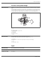
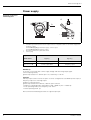
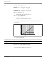
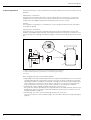
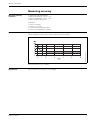
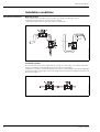
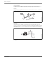
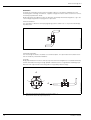
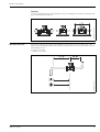
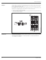
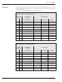
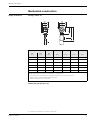
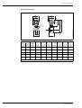
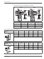
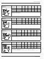
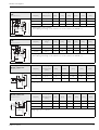
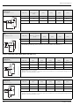
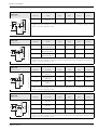
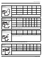
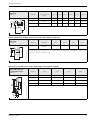
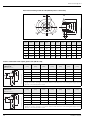
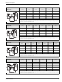
Technical Information
TI 051D/06/en
50097004
Electromagnetic Flow Measuring
System – Two-wire, loop-powered
PROline promag 23 H
Flow measurement in hygiene, food and beverage or
process applications
Features and benefits
• Nominal diameters DN 2...100
• PFA lining for cleaning temperatures up
to +150 °C (+180 °C in preparation)
• Guaranteed product quality, because
suitable for CIP/SIP cleaning and
piggable
• 3A approval and EHEDG-tested
• Measuring accuracy: ± 0.5%
• Robust field housing, IP 67
• “Touch control”: operation without opening the housing - also in Ex
environment
• Communication: HART is standard
• Intrinsically safe Ex ia for installation in
zone 1 (ATEX, FM, CSA, etc.)
• Transmitter supply:
– Non-Ex environment: 12...30 V DC
– Ex environment: 13.9...30 V DC
• Connecting to all mainstream transmitter power supplies and input cards of
process control systems
• Reduced installation and operation
costs
Application
All fluids with a minimum conductivity of
≥ 50 µS/cm can be measured:
• beverages, e.g. fruit juice, beer, wine
• salt solutions
• acids, alkalis, etc.
PROline Promag 23 H
Function and system design
Faraday’s law of induction states that a voltage is induced in a conductor moving in a magnetic
field.
In electromagnetic measuring, the flowing medium corresponds to the moving conductor. The
induced voltage is proportional to the flow velocity and is detected by two measuring electrodes
and transmitted to the amplifier. Flow volume is computed on the basis of the pipe's diameter. The
constant magnetic field is generated by a switched direct current of alternating polarity.
F06-xxxxxxxx-15-xx-xx-xx-001
Measuring principle
Ue = B · L · v
Q=A·v
Ue = induced voltage
B = magnetic induction (magnetic field)
L = electrode gap
v = flow velocity
Q = volume flow
A = pipe cross-section
I = current
Measuring system
The measuring system consists of a transmitter and a sensor.
Compact version: transmitter and sensor form a single mechanical unit.
• Transmitter:
Promag 23 (“Touch Control” without opening the housing, four-line display).
• Sensor:
Promag H (DN 2…100)
Input
Measured variable
Flow rate (proportional to induced voltage)
Measuring range
Typically v = 0.01...10 m/s with the specified measuring accuracy
Operable flow range
Over 1000 : 1
2
Endress+Hauser
PROline Promag 23 H
Output
Output signal
• Current output:
Applied direct current 4...20 mA, input from DC voltage source.
Terminal voltage: 12...30 V DC, 13.9...30 V DC (Ex i)
• Frequency output:
Open collector, passive, galvanically isolated, 30 V DC, 100 mA (250 mA / 20 ms)
Optional configurable as:
– Frequency output:
Full scale frequency 500...10000 Hz (fmax = 12.5 Hz)
or
– Pulse output:
Pulse value and pulse polarity adjustable, pulse width adjustable (0.01...10 s), pulse
frequency max. 50 Hz
or
– Status output:
E.g. for error messages, Empty Pipe Detection, flow direction recognition, limit value
configurable
• Ex i version:
– Power-supply, signal circuits and pulse output with "intrinsically safe" protection rating,
EEx ia IIC and EEx ia IIB, only for connection to certified, intrinsically safe circuits with
the following maximum values: Ui = 30 V, Ii = 150 mA, Pi = 810 mW
Effective internal inductance: negligible
Effective internal capacitance: Ci ≤ 25 nF
– Pulse output:
Maximum values: Ui = 30 V, Ii = 10 mA, Pi = 1 W
Effective internal inductance: negligible
Effective internal capacitance: negligible
Signal on alarm
• Current output → failure response selectable
• Pulse/frequency output → failure response selectable
• Status output → “non-conductive” by fault or power supply failure
Load
see Page 5
Low flow cutoff
Switch points for low flow cut off are selectable.
Galvanic isolation
Outputs are galvanically isolated from sensor and from each other.
Endress+Hauser
3
PROline Promag 23 H
Power supply
Electrical connection
measuring unit
A
2
A
-
+
1
E
4(-) 3(+) 2(-)1(+)
3
1
2
3
F06-2xxxxxxx-04-06-xx-xx-001
Esc
Shielded signal cable (the Ex version requires the use of separate cables for transmitter supply and
frequency output):
Terminal No. 1(+) / 2(–): transmitter supply / current output
Terminal No. 3(+) / 4(–): frequency output
Grounding terminal for signal-cable shield
Service plug
Outputs
Terminal No.
1(+) / 2(−)
3(+) / 4(−)
23***-***********W
Current output HART
−
23***-***********A
Current output HART
Frequency output
Order variant
Mandatory:
A common connecting cable carries supply voltage and measuring output signal:
Current output (passive)
galvanically isolated: 12...30 V DC (Ex i: 13,9...30 V DC), 4...20 mA
Optional:
A binary output can be used as an option. It can be configured as a standard impulse output, a
frequency output or a switching output:
Frequency output (passive)
galvanically isolated: max. 30 V DC, 100 mA, Open Collector
• Frequency operating mode: limit frequency 500...10000 Hz (fmax = 12500 Hz)
• Pulse operating mode: pulse frequency max. 50 Hz
• Status operating mode: yes
We recommend shielded signal cables as a general principle.
4
Endress+Hauser
PROline Promag 23 H
Load
The load has to be calculated as follows:
U S [ V ] – U V [ V ] U S [ V ] – 12 [ V ]
Non Ex area: R L [ Ω ] = ------------------------------------- = ------------------------------------0, 022 [ A ]
IM[A]
U S [ V ] – 13, 9 [ V ]
US[ V ] – UV[ V ]
- = ------------------------------------------Ex area (Ex i): R L [ Ω ] = ------------------------------------0, 022 [ A ]
IM[ A]
RL[Ω] = max. load resistance, load
(cable resistance)
US[V] = external supply voltage of 12...30 V DC
(outgoing supply voltage, transmitter supply unit)
UV[V] = min. supply voltage of 12 V DC
min. supply voltage of 13,9 V DC (Ex i)
(required supply voltage, transmitter)
IM[A] = max. signal transmission current
(failsafe mode current output: 22 mA max. current)
F06-77xxxxxx-05-xx-xx-xx-000
Hinweis!
The minimum load resistance (RL) necessary for a data transfer via HART protocol by way of the
current signal cable is 250 Ω. The minimum external supply voltage (US) therefore has to be
17,5 V DC (non Ex).
Load at the analog current output (non Ex)
– RL – max. load resistance (with HART: min. 250 Ω)
– US – external supply voltage (non Ex)
Cable entry
• Cable entry M20 x 1.5 (8...12 mm)
• Threads for cable entries, Pg 13.5 (5...15 mm), 1/2" NPT, G 1/2"
Cable specifications
Use shielded cables.
Supply voltage
Non-Ex area: 12...30 V DC (with HART: 17.5...30 V DC)
Ex area (Ex i): 13.9...30 V DC (with HART: 19.4...30 V DC)
Power supply failure
• T-DAT™ saves measuring system data if power supply fails
• S-DAT™: exchangeable data storage chip which stores the data of the sensor (nominal
diameter, serial number, calibration factor, zero point, etc.)
Endress+Hauser
5
PROline Promag 23 H
Potential equalisation
Perfect measurement is only ensured when the medium and the sensor have the same electrical
potential.
Metal process connections
Potential matching usually takes place over the metallic process connection in contact with
medium process connections which are directly mounted on the measuring transmitter. This
usually means that additional potential matching measures are unnecessary.
Hinweis!
For installation in metal pipes, it is advisable to connect the ground terminal of the transmitter
housing to the piping.
Plastic process connections
For plastic process connections, potential matching must be ensured between sensor and
medium using additional ground rings. If these ground rings are missing, this can influence accuracy or destroy the measuring transmitter through the electrochemical decomposition of electrodes.
2
3
4
5
F06-xxHxxxxx-17-xx-xx-xx-001
1
1 = allen screw (process connection), 2 = O-ring seal (process connection),
3 = plastic washer (spacer) or ground ring, 4 = O-ring seal (ground ring),
5 = sensor
When using ground rings, note the following points:
• Depending on the option ordered, plastic washers may be installed at the process connections
instead of ground rings. These plastic washers serve only as spacers and have no potential
equalization function. In addition, they provide a sealing function at the interface between the
sensor and process connection. For this reason, with process connections without ground
rings, these plastic washers/seals must not be removed, or must always be installed.
• Ground rings can be ordered separately from E+H as an accessory.
Also make sure that the ground rings are compatible with the electrode material. Otherwise the
danger exists that the electrodes could be destroyed by electrochemical corrosion. You can
find material data on Page 27.
• Ground rings, incl. seals, are mounted inside the process connection.
This has no influence on the installation length. You can find the dimensions of ground rings on
Page 23.
6
Endress+Hauser
PROline Promag 23 H
Measuring accuracy
Reference operating
conditions
To DIN 19200 and VDI/VDE 2641:
• Medium temperature: +28 °C ± 2 K
• Ambient temperature: +22 °C ± 2 K
• Warm-up period: 30 minutes
Installation:
• Inlet run >10 x DN
• Outlet run > 5 x DN
• Sensor and transmitter grounded.
• Sensor centered relative to the pipe.
Signal output: ± 0.5% o.r. ± 4 mm/s (o.r. = of reading)
Supply-voltage fluctuations have no effect within the specified range.
F06-2xxxxxxx-05-xx-xx-xx-001
Max. measured error
Max. measured error in [%] of reading
Repeatability
Endress+Hauser
max. ± 0.25% o.r. ± 2 mm/s (o.r. = of reading)
7
PROline Promag 23 H
Installation conditions
Mounting location
Correct measuring is possible only if the pipe is full. Avoid the following locations:
• Highest point of a pipeline. Risk of air accumulating.
• Directly upstream from an open pipe outlet in a down pipe.
F06-2xxxxxxx-11-00-00-xx-000
Installation instructions
F06-2xxxxxxx-11-00-00-xx-001
Installation of pumps
Do not install the sensor on the intake side of a pump. This precaution is to avoid low pressure
and the consequent risk of damage to the lining of the measuring tube.
It might be necessary to install pulse dampers in systems incorporating reciprocating, diaphragm
or peristaltic pumps. Information on the measuring system's resistance to vibration and shock can
be found on Page 13.
8
Endress+Hauser
PROline Promag 23 H
Partially filled pipes
Partially filled pipes with gradients necessitate a drain-type configuration. The Empty Pipe Detection (EPD) function offers additional protection by detecting empty or partially filled pipes.
F06-2xxxxxxx-11-00-00-xx-002
Achtung!
Risk of solids accumulating. Do not install the sensor at the lowest point in the drain. It is advisable
to install a cleaning valve.
Down pipes
Install a siphon (2) or a vent valve (1) downstream of the sensor in down pipes longer than
5 meters. This precaution is to avoid low pressure and the consequent risk of damage to the lining
of the measuring tube. This measures also prevent the system losing prime, which could cause
air inclusions.
1
1
2
Endress+Hauser
F06-2xxxxxxx-11-00-00-xx-003
>5m
2
vent valve
siphon
9
PROline Promag 23 H
Orientation
An optimum orientation position helps avoid gas and air accumulations and deposits in the
measuring tube. Promag, nevertheless, supplies a range of functions and accessories for correct
measuring of problematic fluids:
Empty Pipe Detection (EPD) ensures the detection of partially filled measuring tubes, e.g. in the
case of degassing fluids or varying process pressures
F06-2xxxxxxx-11-00-00-xx-004
Vertical orientation:
This orientation is ideal for self-emptying piping systems and for use in conjunction with Empty
Pipe Detection.
Horizontal orientation:
The measuring electrodes should be on a horizontal plane. This prevents brief insulation of the
two electrodes by entrained air bubbles.
Achtung!
Empty Pipe Detection functions correctly only when the measuring device is installed horizontally
and the transmitter housing is facing upward. Otherwise there is no guarantee that Empty Pipe
Detection will respond if the measuring tube is only partially filled or empty.
A
1
2
A
1
2
10
F06-23Hxxxxx-11-00-xx-xx-000
2
EPD electrode (Empty Pipe Detection); except for DN 2...8
Measurement electrodes (signal acquisition)
Endress+Hauser
PROline Promag 23 H
F06-2xxxxxxx-11-00-00-xx-006
Vibrations
Secure the piping and the sensor if vibration is severe. Information on resistance to vibration and
shock can be found on Page 13.
If possible, install the sensor well clear of fittings such as valves, T-pieces, elbows, etc. Compliance with the following requirements for the inlet and outlet runs is necessary in order to ensure
measuring accuracy:
• Inlet run: ≥ 5 x DN
• Outlet run: ≥ 2 x DN
F06-2xxxxxxx-11-00-00-xx-005
Inlet and outlet runs
Endress+Hauser
11
PROline Promag 23 H
Adapters
Suitable adapters to (E) DIN EN 545 (double-flange junction sections) can be used to install the
sensor in larger-diameter pipes. The resultant increase in the rate of flow improves measuring
accuracy with very slow-moving fluids.
The nomogram shown here can be used to calculate the pressure loss caused by reducers and
expanders. The nomogram applies only to fluids of viscosity similar to water:
F06-2xxxxxxx-05-05-xx-xx-000
1. Calculate the ratio of the diameters d/D.
2. From the nomogram read off the pressure loss as a function of flow velocity (downstream from
the reduction) and the d/D ratio.
Pressure loss
12
• No pressure loss with nominal diameters DN 08 and larger if the sensor is installed in a pipe of
the same nominal diameter.
• Pressure losses for configurations incorporating adapters according to (E) DIN EN 545
(see “Adapters” on Page 12)
Endress+Hauser
PROline Promag 23 H
Ambient conditions
Ambient temperature
−20...+60 °C
Install the device at a shady location. Avoid direct sunlight, particularly in warm climatic regions.
Storage temperature
–10...+50 °C (preferably +20 °C)
Degree of protection
IP 67 (NEMA 4X)
Shock and vibration
resistance
Acceleration up to 2 g by analogy with IEC 68-2-6
CIP cleaning
Possible
SIP cleaning
Possible
Electromagnetic
compatibility (EMC)
To EN 61326 and NAMUR recommendation NE 21
Process conditions
Medium temperature
range
The permissible medium temperature depends on the sensor and the sealing material:
Sensor:
• –20...+150° C (+180 °C in preparation) for DN 2...25
• −20...+150° C for DN 40...100
Seal:
• EPDM: −20...+130° C
• Silicone: −20...+150° C
• Viton: −20...+150° C
• Kalrez: −20...+150° C
Conductivity
Minimum conductivity ≥ 50 µS/cm (for fluids in general)
Medium pressure range
(nominal pressure)
The permissible nominal pressure depends on the process connection and seal:
• 40 bar: flange, weld nipple (with O-ring seal)
• 16 bar: all other process connections
Pressure tightness
(liner)
Endress+Hauser
Nominal diameter
[mm]
[inch]
2…100
1/12…4"
Measuring tube
lining
PFA
Resistance to partial vacuum of measuring tube lining
Limit values for abs. pressure [mbar] at various
fluid temperatures
25 °C
80 °C
100 °C
130 °C
150 °C
180 °C
0
0
0
0
0
0
13
PROline Promag 23 H
Limiting flow
The diameter of the pipe and the flow rate determine the nominal diameter of the sensor. The optimum velocity of flow is 2...3 m/s. The velocity of flow (v), moreover, has to be matched to the physical properties of the medium:
• v > 2 m/s: for media forming coatings, e.g. in full-fat milk, etc.
Flow characteristics of Promag H (SI units)
Nominal diameter
Recommended
flow rate
Min./max. full scale value
(v ~ 0.3 or 10 m/s)
Factory settings
Full scale value
(v ~ 2.5 m/s)
Pulse weighting
(~ 2 pulse/s)
Creepage
(v ~ 0.04 m/s)
[mm]
[inch]
2
1/12"
0.06…1.8
dm3/min
0.5
dm3/min
0.005
dm3
0.01
dm 3/min
4
5/32"
0.25…7
dm3/min
2
dm3/min
0.025
dm3
0.05
dm 3/min
8
5/16"
1…30
dm3/min
8
dm3/min
0.10
dm3
0.1
dm 3/min
15
1/2"
4…100
dm3/min
25
dm3/min
0.20
dm3
0.5
dm 3/min
25
1"
9…300
dm3/min
75
dm3/min
0.50
dm3
1
dm 3/min
40
1 1/2"
25…700
dm3/min
200
dm3/min
1.50
dm3
3
dm 3/min
50
2"
35…1100
dm3/min
300
dm3/min
2.50
dm3
5
dm 3/min
65
2 1/2"
60…2000
dm3/min
500
dm3/min
5.00
dm3
8
dm 3/min
80
3"
90…3000
dm3/min
750
dm3/min
5.00
dm3
12
dm 3/min
100
4"
145…4700
dm3/min
1200
dm3/min
10.00
dm3
20
dm 3/min
Flow characteristics of Promag H (US units)
Nominal
diameter
14
Recommended
flow rate
Min./max. full scale value
(v ~ 0.3 or 10 m/s)
Factory settings
Full scale value
(v ~ 2.5 m/s)
Pulse weighting
(~ 2 pulse/s)
Creepage
(v ~ 0.04 m/s)
[inch]
[mm]
1/12"
2
0.015…0.5
gal/min
0.1
gal/min
0.001
gal
0.002
gal/min
5/32"
4
0.07…2
gal/min
0.5
gal/min
0.005
gal
0.008
gal/min
5/16"
8
0.25…8
gal/min
2
gal/min
0.02
gal
0.025
gal/min
1/2"
15
1.0…27
gal/min
6
gal/min
0.05
gal
0.10
gal/min
1"
25
2.5…80
gal/min
18
gal/min
0.20
gal
0.25
gal/min
1 1/2"
40
7…190
gal/min
50
gal/min
0.50
gal
0.75
gal/min
2"
50
10…300
gal/min
75
gal/min
0.50
gal
1.25
gal/min
2 1/2"
65
16…500
gal/min
130
gal/min
1
gal
2.0
gal/min
3"
80
24…800
gal/min
200
gal/min
2
gal
2.5
gal/min
4"
100
40…1250
gal/min
300
gal/min
2
gal
4.0
gal/min
Endress+Hauser
PROline Promag 23 H
Mechanical construction
Design / dimensions
Promag H / DN 2...25
DN
PN **
DI
L
K
M
DIN
[mm]
ANSI
[inch]
DIN
[bar]
[mm]
[mm]
[mm]
[mm]
2
−
16/40
2.25
86
43
M 6x4
4
−
16/40
4.5
86
43
M 6x4
8
−
16/40
9.0
86
43
M 6x4
15
−
16/40
16.0
86
43
M 6x4
–
1"
16/40
22.6
86
53
M 6x4
25
−
16/40
26.0
86
53
M 6x4
Fitting length depends on process connections → Page 17 ff.
** The permissible nominal pressure depends on the process connection and seal:
– 40 bar: flange, welding adapter (with O-ring seal)
– 16 bar: all other process connections
Wall-mounting kit (for DN 2...25)
A = 125 mm, B = 88 mm, C = 120 mm, D = Ø 7 mm
Endress+Hauser
15
PROline Promag 23 H
F06-23Hxxxxx-06-00-xx-xx-000
Promag H / DN 40...100
DN
PN
DI
L
A
B
C
K
M
DIN
[mm]
ANSI
[inch]
DIN
[bar]
[mm]
[mm]
[mm]
[mm]
[mm]
[mm]
[mm]
40
1 1/2"
16
35.3
140
340
276
64
128
M 6x4
50
2"
16
48.1
140
365
288
77
153
M 8x4
65
2 1/2"
16
59.9
140
365
288
77
153
M 8x4
80
3"
16
72.6
200
415
313
102
203
M 12x4
100
4"
16
97.5
200
415
313
102
203
M 12x4
Fitting length depends on process connections → Page 24 ff.
16
Endress+Hauser
PROline Promag 23 H
Front view of Promag H / DN 2...25 (without process connection)
DN 2...15
A-A
B
B-B
4
D
0
Ø 44-0.1
70
48.5
±0.1
±0.1
=
=
A
±0.1
±0.1
= =
M6
M6
C
0
Ø 34-0.1
60
41.6
=±0.1 = ±0.1
4
B
6
= ±0.1 = ±0.1
6
28
8.5
8.5
24
42
52
43
53
DN
C
[mm]
D (DIN)
[mm]
D (ANSI)
[mm]
2...8
9
–
–
15
16
–
–
25
–
26
22.6
F06-5xHxxxxx-06-05-08-xx-000
A
DN 25
Process connections with O-ring seals (DN 2…25)
F06-xxHxxxxx-06-09-07-xx-010
Weld nipple for pipe ISO 2463
1.4404 / 316L
5*H**-B***********
F06-xxHxxxxx-06-09-07-xx-012
Weld nipple for pipe IPS
1.4404 / 316L
5*H**-C***********
Endress+Hauser
Sensor
Piping
di
G
L
HxW
DN [mm]
Pipe
[mm]
[mm]
[mm]
[mm]
2…8
13.5 x 1.6
10.3
13.5
20.3
60 x 42
15
21.3 x 1.6
18.1
21.3
20.3
60 x 42
25 (DIN)
33.7 x 2
29.7
33.7
20.3
70 x 52
Fitting length = (2 x L) + 86 mm
Sensor
Piping
di
G
L
HxW
DN [mm]
Pipe (ODT / SMS)
[mm]
[mm]
[mm]
[mm]
2…8
13.5 x 2.3
9.0
13.5
20.3
60 x 42
15
21.3 x 2.65
16.0
21.3
20.3
60 x 42
1" (25 ANSI)
33.7 x 3.25
27.2
33.7
22.3
70 x 52
Fitting length = (2 x L) + 86 mm
17
PROline Promag 23 H
F06-xxHxxxxx-06-09-07-xx-014
Flange PN 40 / DIN 2635
1.4404 / 316L
5*H**-D***********
F06-xxHxxxxx-06-09-07-xx-015
Flange Cl 150 / ANSI 16.5
1.4404 / 316L
5*H**-E***********
F06-xxHxxxxx-06-09-07-xx-016
Flange 20K / JIS B2238
1.4404 / 316L
5*H**-F***********
F06-xxHxxxxx-06-09-07-xx-029
Flange PN 16 / DIN 2501
PVDF
5*H**-G***********
18
Sensor
Piping
di
G
L
LK
M
HxW
DN [mm]
Flange
[mm]
[mm]
[mm]
[mm]
[mm]
[mm]
2…8
DN 15
17.3
95
56.2
65
14
60 x 42
15
DN 15
17.3
95
56.2
65
14
60 x 42
25 (DIN)
DN 25
28.5
115
56.2
85
14
70 x 52
Fitting length = (2 x L) + 86 mm
Fitting length to DVGW (200 mm)
Sensor
Piping
di
G
L
LK
M
HxW
DN [mm]
Flange [inch]
[mm]
[mm]
[mm]
[mm]
[mm]
[mm]
2…8
1/2"
15.7
89
66.0
60.5
15.7
60 x 42
15
1/2"
16.0
89
66.0
60.5
15.7
60 x 42
1" (25 ANSI)
1"
26.7
108
71.8
79.2
15.7
70 x 52
Fitting length = (2 x L) + 86 mm
Sensor
Piping
di
G
L
LK
M
HxW
DN [mm]
Flange
[mm]
[mm]
[mm]
[mm]
[mm]
[mm]
2…8
ND 10
10
90
67
65
15
60 x 42
15
ND 15
16
95
67
70
15
60 x 42
25 (DIN)
ND 25
26
125
67
95
19
70 x 52
Fitting length = (2 x L) + 86 mm
Sensor
Piping
di
G
L
M
LK
HxW
DN [mm]
Flange
[mm]
[mm]
[mm]
[mm]
[mm]
[mm]
2…8
DN 15
15.7
95
57
14
65
60 x 42
15
DN 15
15.7
95
57
14
65
60 x 42
25 (DIN)
DN 25
27.3
115
57
14
85
70 x 52
– Fitting length = (2 x L) + 86 mm
– Fitting length to DVGW (200 mm)
– The requisite ground rings can be ordered as accessories (Order code: DK5HR-****)
Endress+Hauser
PROline Promag 23 H
F06-xxHxxxxx-06-09-07-xx-029
Flange Cl 150 / ANSI 16.5
PVDF
5*H**-H***********
F06-xxHxxxxx-06-09-07-xx-029
Flange 10K / JIS B2238
PVDF
5*H**-J***********
External pipe thread ISO 228 /
DIN 2999, 1.4404 / 316L
5*H**-K***********
L
F06-xxHxxxxx-06-09-07-xx-025
HxB
di
G
S
Internal pipe thread ISO 228 /
DIN 2999, 1.4404 / 316L
5*H**-L***********
L
Endress+Hauser
F06-xxHxxxxx-06-09-07-xx-027
HxB
di
G
D
S
Sensor
Piping
di
G
L
M
LK
HxW
DN [mm]
Flange [inch]
[mm]
[mm]
[mm]
[mm]
[mm]
[mm]
2…8
1/2"
15.7
95
57
16
60
60 x 42
15
1/2"
15.7
95
57
16
60
60 x 42
1" (25 ANSI)
1"
27.3
115
57
16
79
70 x 52
– Fitting length = (2 x L) + 86 mm
– The requisite ground rings can be ordered as accessories (Order code: DK5HR-****)
Sensor
Piping
di
G
L
M
LK
HxW
DN [mm]
Flange
[mm]
[mm]
[mm]
[mm]
[mm]
[mm]
2…8
ND 15
15.7
95
57
15
70
60 x 42
15
ND 15
15.7
95
57
15
70
60 x 42
25 (DIN)
ND 25
27.3
125
57
19
90
70 x 52
– Fitting length = (2 x L) + 86 mm
– The requisite ground rings can be ordered as accessories (Order code: DK5HR-****)
Sensor
Piping
di
G
L
S
HxW
DN [mm]
Internal thread
[inch]
[mm]
[inch]
[mm]
[mm]
[mm]
2…8
R 3/8"
10
3/8"
40
10.1
60 x 42
15
R 1/2"
16
1/2"
40
13.2
60 x 42
1" (25 ANSI)
R 1"
25
1"
40
16.5
70 x 52
Fitting length = (2 x L) + 86 mm
Sensor
Piping
di
G
D
L
S
HxW
DN [mm]
External thread
[inch]
[mm]
[inch]
[mm]
[mm]
[mm]
[mm]
2…8
Rp 3/8"
8.9
3/8"
22
45
13
60 x 42
15
Rp 1/2"
16.0
1/2"
27
45
14
60 x 42
1" (25 ANSI)
Rp 1"
27.2
1"
40
49
17
70 x 52
Fitting length = (2 x L) + 86 mm
19
PROline Promag 23 H
F06-xxHxxxxx-06-09-07-xx-024
Hose connection
1.4404 / 316L
5*H**-M/N/P***********
F06-xxHxxxxx-06-09-07-xx-028
Adhesive fitting
PVC
5*H**-R/S***********
Sensor
Hose (LW)
di
LW
L
HxW
DN [mm]
Inside diameter
[mm]
[mm]
[mm]
[mm]
[mm]
2…8
13
10.0
13
49
60 x 42
15
16
12.6
16
49
60 x 42
15
19
16.0
19
49
70 x 52
– Fitting length = (2 x L) + 86 mm
Sensor
Piping
di
G
L
HxW
DN [mm]
Adhesive connection
[inch]
[mm]
[mm]
[mm]
[mm]
2…8
1/2"
21.5
27.3
28.0
60 x 42
15
20 x 2
20.2
27.0
38.5
60 x 42
– Fitting length = (2 x L) + 86 mm
– The requisite ground rings can be ordered as accessories (Order code: DK5HR-****)
Process connections with aseptic gasket seals (DN 2...25 )
F06-xxHxxxxx-06-09-07-xx-011
Weld nipple for pipe DIN 11850
1.4404 / 316L
5*H**-U***********
F06-xxHxxxxx-06-09-07-xx-013
Weld nipple for ODT/SMS
1.4404 / 316L
5*H**-V***********
20
Sensor
Piping
di
G
L
HxW
DN [mm]
Pipe
[mm]
[mm]
[mm]
[mm]
2…8
14 x 2
10
14
23.3
60 x 42
15
20 x 2
16
20
23.3
60 x 42
25 (DIN)
30 x 2
26
30
23.3
70 x 52
– Fitting length = (2 x L) + 86 mm
– If pigs are used for cleaning, it is essential to take the inside diameters of measuring tube (Page 15) and
process connection (di) into account.
Sensor
Piping
di
G
L
HxW
DN [mm]
Pipe
[mm]
[mm]
[mm]
[mm]
2…8
12.7 x 1.65
9.4
12.7
16.1
60 x 42
15
19.1 x 1.65
15.8
19.1
16.1
60 x 42
1" (25 ANSI)
24.5 x 1.65
22.1
25.4
16.1
70 x 52
– Fitting length = (2 x L) + 86 mm
– If pigs are used for cleaning, it is essential to take the inside diameters of measuring tube (Page 15) and
process connection (di) into account.
Endress+Hauser
PROline Promag 23 H
F06-xxHxxxxx-06-09-07-xx-023
Clamp ISO 2852
1.4404 / 316L
5*H**-W***********
F06-xxHxxxxx-06-09-07-xx-019
Clamp DIN 32676
1.4404 / 316L
5*H**-0***********
F06-xxHxxxxx-06-09-07-xx-020
Tri-Clamp
1.4404 / 316L
5*H**-1***********
F06-xxHxxxxx-06-09-07-xx-017
Coupling DIN 11851
1.4404 / 316L
5*H**-2***********
Endress+Hauser
Sensor
Piping
di
G
L
HxW
DN [inch]
Clamp
[mm]
[mm]
[mm]
[mm]
1" (25 ANSI)
Pipe 25.4 x 1.65
(ISO; 1")
22.6
50.5
44.5
70 x 52
– Fitting length = (2 x L) + 86 mm
– If pigs are used for cleaning, it is essential to take the inside diameters of measuring tube (Page 15) and
process connection (di) into account.
Sensor
Piping
di
G
L
HxW
DN [mm]
Clamp
[mm]
[mm]
[mm]
[mm]
2…8
Pipe 14 x 2
(DIN 11850; DN 10)
10
34.0
41.0
60 x 42
15
Pipe 20 x 2
(DIN 11850; DN 15)
16
34.0
41.0
60 x 42
25 (DIN)
Pipe 30 x 2
(DIN 11850; DN 25)
26
50.5
44.5
70 x 52
– Fitting length = (2 x L) + 86 mm
– If pigs are used for cleaning, it is essential to take the inside diameters of measuring tube (Page 15) and
process connection (di) into account.
Sensor
Piping
di
G
L
HxW
DN [mm]
Tri-Clamp
[mm]
[mm]
[mm]
[mm]
2…8
Pipe 12.7 x 1.65
(ODT 1/2")
9.4
25.0
28.5
60 x 42
15
Pipe 19.1 x 1.65
(ODT 3/4")
15.8
25.0
28.5
60 x 42
1" (25 ANSI)
Pipe 24.5 x 1.65
(ODT 1")
22.1
50.4
28.5
70 x 52
– Fitting length = (2 x L) + 86 mm
– If pigs are used for cleaning, it is essential to take the inside diameters of measuring tube (Page 15) and
process connection (di) into account.
Sensor
Piping
di
G
L
HxW
DN [mm]
Screw union
[mm]
[mm]
[mm]
[mm]
2…8
Pipe 12 x 1
(DN 10)
10
Rd 28 x 1/8"
44
60 x 42
15
Pipe 18 x 1 or 1.5
(DN 15)
16
Rd 34 x 1/8"
44
60 x 42
25 (DIN)
Pipe 28 x 1 or 1.5
(DN 25)
26
Rd 52 x 1/6"
52
70 x 52
– Fitting length = (2 x L) + 86 mm
– If pigs are used for cleaning, it is essential to take the inside diameters of measuring tube (Page 15) and
process connection (di) into account.
21
PROline Promag 23 H
F06-xxHxxxxx-06-09-07-xx-021
Coupling DIN 11864-1
1.4404 / 316L
5*H**-3***********
F06-xxHxxxxx-06-09-07-xx-022
Flange DIN 11864-2 Form A
1.4404 / 316L
5*H**-4***********
F06-xxHxxxxx-06-09-07-xx-026
Coupling SMS 1145
1.4404 / 316L
5*H**-5***********
Sensor
Piping
di
G
L
HxW
DN [mm]
Screw union
[mm]
[mm]
[mm]
[mm]
2…8
Pipe 13 x 1.5
(DIN 11850; DN 10)
10
Rd 28 x 1/8"
42
60 x 42
15
Pipe 19 x 1.5
(DIN 11850; DN 15)
16
Rd 34 x 1/8"
42
60 x 42
25 (DIN)
Pipe 29 x 1.5
(DIN 11850; DN 25)
26
Rd 52 x 1/6"
49
70 x 52
– Fitting length = (2 x L) + 86 mm
– If pigs are used for cleaning, it is essential to take the inside diameters of measuring tube (Page 15) and
process connection (di) into account.
Sensor
Piping
di
G
L
LK
M
HxW
DN [mm]
Flange
[mm]
[mm]
[mm]
[mm]
[mm]
[mm]
2…8
Pipe 13 x 1.5
(DIN 11850; DN 10)
10
54
48.5
37
9
60 x 42
15
Pipe 19 x 1.5
(DIN 11850; DN 15)
16
59
48.5
42
9
60 x 42
25 (DIN)
Pipe 29 x 1.5
(DIN 11850; DN 25)
26
70
48.5
53
9
70 x 52
– Fitting length = (2 x L) + 86 mm
– If pigs are used for cleaning, it is essential to take the inside diameters of measuring tube (Page 15) and
process connection (di) into account.
Sensor
Piping
di
G
L
HxW
DN [mm]
Screw union
[inch]
[mm]
[mm]
[mm]
[mm]
1" (25 ANSI)
1"
22.1
Rd 40 x 1/6"
30.8
70 x 52
– Fitting length = (2 x L) + 86 mm
– If pigs are used for cleaning, it is essential to take the inside diameters of measuring tube (Page 15) and
process connection (di) into account.
Process connections orderable only as accessories (with O-ring seal, DN 2...25)
External pipe thread NPT
1.4404 / 316L
DKH**-GD**
L
22
F06-xxHxxxxx-06-09-07-xx-025
HxB
di
G
S
Sensor
Piping
di
G
L
S
HxW
DN [mm]
Internal thread
[inch]
[mm]
[inch]
[mm]
[mm]
[mm]
2…8
NPT 3/8"
10
3/8"
50
15.5
60 x 42
15
NPT 1/2"
16
1/2"
50
20.0
60 x 42
1" (25 ANSI)
NPT 1"
25
1"
55
25.0
70 x 52
Fitting length = (2 x L) + 86 mm
Endress+Hauser
PROline Promag 23 H
Internal pipe thread NPT
1.4404 / 316L
DKH**-GC**
L
F06-xxHxxxxx-06-09-07-xx-027
HxB
G
di
D
S
Sensor
Piping
di
G
D
L
S
HxW
DN [mm]
External thread
[inch]
[mm]
[inch]
[mm]
[mm]
[mm]
[mm]
2…8
NPT 3/8"
8.9
3/8"
22
45
13
60 x 42
15
NPT 1/2"
16.0
1/2"
27
45
14
60 x 42
1" (25 ANSI)
NPT 1"
27.2
1"
40
49
17
70 x 52
Fitting length = (2 x L) + 86 mm
Process connections orderable only as accessories (with asceptic gasket seal)
F06-xxHxxxxx-06-09-07-xx-018
Tri-Clamp
1.4404 / 316L
DKH**-HF***
Sensor
Piping
di
G
L
HxW
DN [mm]
Tri-Clamp
[mm]
[mm]
[mm]
[mm]
15
Pipe 25.4 x 1.65
(ODT; 1")
22.1
50.4
28.5
60 x 42
– Fitting length = (2 x L) + 86 mm
– If pigs are used for cleaning, it is essential to take the inside diameters of measuring tube (Page 15) and
process connection (di) into account.
Ground rings available as accessories (PVDF flange / PVC adhesive coupling)
3.5
0.5
1.9
3.4
4.5
Endress+Hauser
Sensor
di
B
C
D
DN [mm]
[mm]
[mm]
[mm]
[mm]
2…8
9.0
22.0
17.6
33.9
15
16.0
29.0
24.6
33.9
25 (DIN)
22.6
36.5
31.2
43.9
1" (25 ANSI)
26.0
39.0
34.6
43.9
F06-xxHxxxxx-06-09-07-xx-030
ØB
ØC
Ø di
ØD
Ground ring
1.4435 / 316L, Alloy C-22
Titanium (Pt/Rh-coated)
DK5HR-****
23
PROline Promag 23 H
Front view of Promag H / DN 40...100 (without process connection)
L
K
Z-Z
F
60
°
±0
.5 °
F06-5xHxxxxx-06-05-08-xx-001
E
D
C
B
A
90° ±0.5°
Z
Z
G
H
DN
[mm]
A
[mm]
B
[mm]
C
[mm]
D
[mm]
E
[mm]
F
[mm]
G
[mm]
N
[mm]
L
[mm]
K
[mm]
40
122.0
86
71.0
51.0
35.3
M8
15
18
–
4
50
147.0
99
83.5
63.5
48.1
M8
15
18
–
4
65
147.0
115
100.0
76.1
59.9
M8
15
18
6
–
80
197.0
141
121.0
88.9
72.6
M 12
15
20
–
4
100
197.0
162
141.5
114.3
97.5
M 12
15
20
6
–
Process connections with aseptic gasket seals (DN 40...100)
F06-xxHxxxxx-06-09-07-xx-002
Weld nipple for pipe DIN 11850
1.4404 / 316L
5*H**-U***********
F06-xxHxxxxx-06-09-07-xx-002
Weld nipple for pipe ODT
1.4404 / 316L
5*H**-V***********
24
DN
[mm]
di
[mm]
G
[mm]
D
[mm]
L
[mm]
L1
[mm]
LK
[mm]
40
38.0
43
92
42
19
71.0
50
50.0
55
105
42
19
83.5
65
66.0
72
121
42
21
100.0
80
81.0
87
147
42
24
121.0
100
100.0
106
168
42
24
141.5
– Fitting length = (2 x L) + 140 mm (DN 40...65) / + 200 mm (DN 80...100)
– If pigs are used for cleaning, it is essential to take the inside diameters of measuring tube (Page 15) and
process connection (di) into account.
DN
[mm]
di
[mm]
G
[mm]
D
[mm]
L
[mm]
L1
[mm]
LK
[mm]
40
35.3
40
92
42
19
71.0
50
48.1
55
105
42
19
83.5
65
59.9
66
121
42
21
100.0
80
72.6
79
147
42
24
121.0
100
97.5
104
168
42
24
141.5
– Fitting length = (2 x L) + 140 mm (DN 40...65) / + 200 mm (DN 80...100)
– If pigs are used for cleaning, it is essential to take the inside diameters of measuring tube (Page 15) and
process connection (di) into account.
Endress+Hauser
PROline Promag 23 H
F06-xxHxxxxx-06-09-07-xx-005
Clamp ISO 2852
1.4404 / 316L
5*H**-W***********
F06-xxHxxxxx-06-09-07-xx-008
Clamp DIN 32676
1.4404 / 316L
5*H**-0***********
F06-xxHxxxxx-06-09-07-xx-001
Coupling DIN 11851
1.4404 / 316L
5*H**-2***********
Endress+Hauser
di
[mm]
G
[mm]
D
[mm]
L
[mm]
LK
[mm]
40
35.6
50.5
92
68.5
71.0
50
48.6
64.0
105
68.5
83.5
65
60.3
77.5
121
68.5
100.0
80
72.9
91.0
147
68.5
121.0
100
97.6
119.0
168
68.5
141.5
– Fitting length = (2 x L) + 140 mm (DN 40...65) / + 200 mm (DN 80...100)
– If pigs are used for cleaning, it is essential to take the inside diameters of measuring tube (Page 15) and
process connection (di) into account.
DN
[mm]
di
[mm]
G
[mm]
D
[mm]
L
[mm]
LK
[mm]
40
38
50.5
92
61.5
71.0
50
50
64.0
105
61.5
83.5
65
66
91.0
121
68.0
100.0
80
81
106.0
147
68.0
121.0
100
100
119.0
168
68.0
141.5
– Fitting length = (2 x L) + 140 mm (DN 40...65) / + 200 mm (DN 80...100)
– If pigs are used for cleaning, it is essential to take the inside diameters of measuring tube (Page 15) and
process connection (di) into account.
DN
F06-xxHxxxxx-06-09-07-xx-004
Tri-Clamp
1.4404 / 316L
5*H**-1***********
DN
[mm]
di
G
D
L
LK
[mm]
[inch]
[mm]
[mm]
[mm]
[mm]
[mm]
40
1 1/2"
34.8
50.4
92
68.6
71.0
50
2"
47.5
63.9
105
68.6
83.5
65
−
60.2
77.4
121
68.6
100.0
80
3"
72.9
90.9
147
68.6
121.0
100
4"
97.4
118.9
168
68.6
141.5
– Fitting length = (2 x L) + 140 mm (DN 40...65) / + 200 mm (DN 80...100)
– If pigs are used for cleaning, it is essential to take the inside diameters of measuring tube (Page 15) and
process connection (di) into account.
DN
[mm]
di
[mm]
G
[mm]
D
[mm]
L
[mm]
LK
[mm]
40
38
Rd 65 x 1/6"
92
72
71.0
50
50
Rd 78 x 1/6"
105
74
83.5
65
66
Rd 95 x 1/6"
121
78
100.0
80
81
Rd 110 x 1/4"
147
83
121.0
100
100
Rd 130 x 1/4"
168
92
141.5
– Fitting length = (2 x L) + 140 mm (DN 40...65) / + 200 mm (DN 80...100)
– If pigs are used for cleaning, it is essential to take the inside diameters of measuring tube (Page 15) and
process connection (di) into account.
25
PROline Promag 23 H
F06-xxHxxxxx-06-09-07-xx-006
Coupling DIN 11864-1 Form A
1.4404 / 316L
5*H**-3***********
F06-xxHxxxxx-06-09-07-xx-007
Flange DIN 11864-2 Form A
1.4404 / 316L
5*H**-4***********
F06-xxHxxxxx-06-09-07-xx-000
Coupling SMS 1145
1.4404 / 316L
5*H**-5***********
F06-xxHxxxxx-06-09-07-xx-003
Coupling ISO 2853
1.4404 / 316L
5*H**-6***********
26
DN
[mm]
di
[mm]
G
[mm]
D
[mm]
L
[mm]
LK
[mm]
40
38
Rd 65 x 1/6"
92
71
71.0
50
50
Rd 78 x 1/6"
105
71
83.5
65
66
Rd 95 x 1/6"
121
76
100.0
80
81
Rd 110 x 1/4"
147
82
121.0
100
100
Rd 130 x 1/4"
168
90
141.5
– Fitting length = (2 x L) + 140 mm (DN 40...65) / + 200 mm (DN 80...100)
– If pigs are used for cleaning, it is essential to take the inside diameters of measuring tube (Page 15) and
process connection (di) into account.
DN
[mm]
di
[mm]
G
[mm]
D
[mm]
L
[mm]
LK1
[mm]
LK2
[mm]
40
38
82
92
64
71.0
65
50
50
94
105
64
83.5
77
65
66
113
121
64
100.0
95
80
81
133
147
98
121.0
112
100
100
159
168
98
141.5
137
– Fitting length = (2 x L) + 140 mm (DN 40...65) / + 200 mm (DN 80...100)
– If pigs are used for cleaning, it is essential to take the inside diameters of measuring tube (Page 15) and
process connection (di) into account.
DN
[mm]
di
[mm]
G
[mm]
D
[mm]
L
[mm]
LK
[mm]
40
35.5
Rd 60 x 1/6"
92
63
71.0
50
48.5
Rd 70 x 1/6"
105
65
83.5
65
60.5
Rd 85 x 1/6"
121
70
100.0
80
72.0
Rd 98 x 1/6"
147
75
121.0
100
97.6
Rd 132 x 1/6"
168
70
141.5
– Fitting length = (2 x L) + 140 mm (DN 40...65) / + 200 mm (DN 80...100)
– If pigs are used for cleaning, it is essential to take the inside diameters of measuring tube (Page 15) and
process connection (di) into account.
DN
[mm]
di
[mm]
G
[mm]
D
[mm]
L
[mm]
LK
[mm]
40
35.6
50.6
92
61.5
71.0
50
48.6
64.1
105
61.5
83.5
65
60.3
77.6
121
61.5
100.0
80
72.9
91.1
147
61.5
121.0
100
97.6
118.1
168
61.5
141.5
– Fitting length = (2 x L) + 140 mm (DN 40...65) / + 200 mm (DN 80...100)
– If pigs are used for cleaning, it is essential to take the inside diameters of measuring tube (Page 15) and
process connection (di) into account.
Endress+Hauser
PROline Promag 23 H
Weight
Weight data of Promag H in [kg]
Nominal diameter
Compact version
[mm]
[inch]
DIN
2
1/12"
5.2
4
5/32"
5.2
8
5/16"
5.3
15
1/2"
5.4
25
1"
5.5
40
1 1/2"
6.5
50
2"
9.0
65
2 1/2"
9.5
80
3"
19.0
100
4"
18.5
Transmitter Promag (compact version): 3.4 kg
(Weight data valid for standard pressure ratings and without packaging material)
Materials
Transmitter housing:
Compact housing: powder coated die-cast aluminium
Sensor housing:
Stainless steel 1.4301
Wall mounting (holder panel):
Stainless steel 1.4301
Measuring tube:
Stainless steel 1.4301 or 1.4306/304L
Flanges:
• All connections 1.4404/316L
• Flanges (DIN, ANSI, JIS) made of PVDF
• Adhesive fitting made of PVC
Ground rings:
• Standard: 1.4435/316L
• Option: tantalum, platinum (base material: titanium Grade 2, platinum coating min. 12 µm),
Alloy C-22
Electrodes:
• Standard: 1.4435
• Option: Alloy C-22, tantalum, platinum/rhodium 80/20 (up to DN 25 only)
Seals:
• DN 2...25: O-ring (EPDM, Viton, Kalrez) or gasket seal (EPDM, silicone, Viton)
• DN 40...100: gasket seal (EPDM, silicone)
Endress+Hauser
27
PROline Promag 23 H
Weld nipple in 1.4404 / 316L (with O-ring)
to ISO 2463, IPS, ISO 228 / DIN 2999
F06-xxHxxxxx-05-xx-xx-xx-000
Material load curves
F06-xxHxxxxx-05-xx-xx-xx-001
Weld nipple in 1.4404 / 316L (with gasket seal)
to DIN 11850, ODT, Clamp (ODT, ISO 2852, DIN 32676), coupling (DIN 11851, DIN 11864-1,
ISO 2853, SMS 1145), flange DIN 11864-2
F06-xxHxxxxx-05-xx-xx-xx-002
Flange material: 1.4404 / 316L, PVDF; Adhesive fitting: PVC-U
to DIN 2635 and 2501
28
Endress+Hauser
PROline Promag 23 H
F06-xxHxxxxx-05-xx-xx-xx-003
Flange material: 316L, PVDF
to ANSI B16.5
Flange material: 1.4404 / 316L, PVDF
to JIS B2238
Fitted electrodes
Measuring electrodes and EPD electrodes
• Standard with: 1.4435, Alloy C-22, tantalum, platinum/rhodium
• DN 2...8: without EPD electrode
Process connection
• With O-ring: welding nipples (ISO 2463, IPS), flanges (DIN, ANSI, JIS), PVDF flanges (DIN,
ANSI, JIS), external pipe thread, internal pipe thread, hose connection, PVC adhesive fittings
• With gasket seal: weld nipples (DIN 11850, ODT), clamps (ODT, ISO 2852, DIN 32676),
threaded fasteners (DIN 11851, DIN 11864-1, ISO 2853, SMS 1145), flanges (DIN 11864-2)
Surface roughness
• PFA liner: ≤ 0.3 µm
• Electrodes:
– 1.4435, Alloy C-22: ≤ 0.4 µm
– Tantalum, platinum/rhodium: ≤ 0.8 µm
• Process connection Promag H: ≤ 0.8 µm
(all data relate to parts in contact with medium)
Endress+Hauser
29
PROline Promag 23 H
Human interface
Display elements
• Liquid-crystal display: four lines with 16 characters per line
• Custom configurations for presenting different measured values and status variables
• 2 totalizers
Operating elements
Unified (PROline-) operation concept:
Local operation with three optical keys (–, +, E)
Remote operation
Operation via HART
Certificates and approvals
Ex approval
Information on the currently available Ex-rated versions (ATEX, FM, CSA, etc.) is available on
request from your E+H sales outlet. All information relevant to explosion protection is available in
separate Ex documents that you can order as necessary.
Sanitary compatibility
3A authorization and EHEDG-tested
Seals in conformity with FDA (except Kalrez seals)
CE mark
The measuring system is in conformity with the statutory requirements of the EC Directives.
Endress+Hauser confirms successful testing of the device by affixing to it the CE mark.
Other standards and
guidelines
EN 60529:
Degrees of protection by housing (IP code)
EN 61010:
“Protection Measures for Electrical Equipment for Measurement, Control, Regulation and
Laboratory Procedures”.
EN 61326 (IEC 1326):
Electromagnetic compatibility (EMC requirements)
NAMUR NE 21:
Association for Standards for Control and Regulation in the Chemical Industry
Ordering information
The E+H service organisation can provide detailed ordering information and information on the
order codes on request.
Accessories
Various accessories, which can be ordered separately from Endress+Hauser, are available for the
transmitter and the sensor. The E+H service organisation can provide detailed information on
request.
30
Endress+Hauser
PROline Promag 23 H
Supplementary documentation
Endress+Hauser
System Information Promag (SI 028D/06/en)
Technical Information Promag 23 P (TI 049D/06/en)
Operating Instructions Promag 23 (BA 045D/06/en and BA 050D/06/en)
Supplementary documentation on Ex-ratings: ATEX, FM, CSA, etc.
31
Subject to modification
Endress+Hauser
Gmbh+Co.
Instruments International
P.O. Box 2222
D-79574 Weil am Rhein
Germany
Tel. (07621) 975-02
Tx 773926
Fax (07621) 975 345
http://www.endress.com
[email protected]
TI 051D/06/en/08.01
50097004
FM+SGML 6.0