1
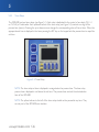
protea
GPR -800
®
ADVANCED PROTEIN RECOVERY FROM GEL SAMPLES
USER’S MANUAL
www.proteabio.com • 2
Copyright
This manual is copyrighted with all rights reserved. No portion of this manual may be copied or reproduced by any means
without the prior written consent of Protea Biosciences, Inc. (Protea). While every precaution has been taken in the
preparation of this document, Protea assumes no liability to any party for any loss or damage caused by errors or omissions
or by statements resulting from negligence, accident, or any other cause. Protea further assumes no liability arising out of the
application or use of any product or system described, herein; nor any liability for incidental or consequential damages arising
from the use of this document.
Trademarks
The Protea Gel Protein Recovery System® (hereafter “GPR-800”) is a trademark of Protea Biosciences, Inc. Protea reserves
the right to make changes without further notice to any product or system described herein to improve reliability, function, or
design.
© 2010 Protea Biosciences, Inc. All Rights Reserved.
Revision 1.0, 04/2010
Protea Biosciences, Inc.
955 Hartman Run Rd.
Morgantown, WV 26507
Main Switchboard:
Fax:
(877) 776-8321
(304) 292-7101
Safety Warning and Limitation of Liability
Use of the GPR-800 involves the use of and potential exposure to hazardous materials, and therefore, the system is intended
for use only by professionals with adequate training and experience in handling of the materials involved. Protea cannot be
held responsible for any injuries to persons or property or for any other damage resulting from the improper use of this
equipment or its use in any manner not specifically described in this manual. Furthermore, Protea disclaims all responsibility
and liability in connection with any accidents arising from any use of the GPR-800 in situations where inadequate safety
procedures are in place or where such procedures have not been followed.
3 • 877.776.8321
Warranty
WARRANTY: Products are Warranted to be free of defects in materials and workmanship, and to perform
to the published specifications, for a period of one year from the date of the product’s shipment (see
current Protea Biosciences, Inc. catalog for additional warranty language and Terms of Sale).
www.proteabio.com • 4
Preface
This user’s manual is written for use with the Protea Biosciences, Inc. (Protea) Gel Protein Recovery System 800
(hereafter “GPR-800”). This device’s intended use is to serve as a platform for developing the gel protein recovery
process. The audience of this device is the intended eventual end users (i.e., practitioners) of the device.
5 • 877.776.8321
Contents
1
Introduction
8
1.1
Introducing the GPR-800
8
1.2
About the User’s Manual
8
1.3
Technical Specifications9
1.3.1 Physical Dimensions 9
1.3.2 Environmental Ranges
9
1.3.3 Consumables Storage Specifications
9
1.3.4 Electrical Specifications
9
1.3.5 Chemical Compatibility
10
1.3.6 Flammable Liquids
10
2
Safety
2.1
Safety Stops
2.1.1 Unit Safety Cover
2.1.2 Chip Holder
2.2
Electrical Safety
11
13
13
14
15
3
Component Locations
3.1
External and Internal Parts
3.2
System Accessories
16
16
19
4
Installation and Preparation
4.1
Accessory Equipment
4.2
Initial Setup
4.2.1 Unpacking and Setup of the GPR-800
20
20
20
20
www.proteabio.com • 6
5
Instructions for Use23
5.1
General Operation
23
5.2
Operating Controls: Keypads and Timer Relays23
5.2.1 Keypads
24
5.2.2 Timer Relays
26
5.3
Gel Protein Recovery
27
5.3.1 Priming the Protein GPRchip for Gel Protein Recovery
27
5.3.2 Sample Extraction and Collection
28
5.3.3 Stopping Electroelution
30
5.3.4 LC-MS Analysis of Intact Proteins
32
5.3.5 GPR-800 Application Kits
33
5.4
Power Off
36
6
Cleaning and Maintenance
6.1
Cleaning
6.2
Maintenance
37
37
37
7
Troubleshooting
38
8
Gel Guidelines for Optimal GPR Performances
8.1
SDS-Page Gel Reccomendations for GPR-800 Samples
8.1.1 SDS-Page Gel
8.1.2 Electrophoresis
8.1.3 Staining and Visualization
8.1.4 Gel Sample Handling and Storage
8.1.5 Optional Buffer Formulations
40
40
40
40
41
46
47
9
GPR Consumables
48
10
Notes
50
7 • 877.776.8321
1 Introduction
This chapter contains introductory information on the Gel Protein Recovery System (GPR-800), including
specifications. It also provides information about this User’s Manual.
1.1
INTRODUCING THE GPR-800
The GPR-800 is intended for use in a research laboratory to support extraction of intact proteins, peptide mixtures
from protein digests, and other biomolecules from polyacrylamide gel plugs by electroelution or electroextraction.
The GPR-800 is designed to efficiently recover biomolecules from acrylamide gel plugs via a sample recovery process
that minimizes set-up, operation time, and user interaction.
The operator begins the process by excising poylacrylamide gel plugs and placing them into the designated GPRchip
receptacles. The GPR-800 is primed by the addition of GPR Electroelution Buffer into the electrode reservoirs.
After completing the system setup, the operator starts the sample recovery process using the front panel interface on
the GPR-800. After electroelution the recovered protein samples are transferred to vials for subsequent detergent
degradation and desalting using SPE or other methods prior to mass spectrometry.
For instructions on general use of the GPR-800, see the General Operation section starting on page 23 of this
manual.
1.2
ABOUT THE USER’S MANUAL
This manual contains information on the features and functions of the GPR-800. It provides instructions on operating
the unit. Read the Safety Information starting on page 11 prior to setting up or operating the GPR-800, as this
section contains information necessary for the safe operation of the unit. Important information contained in this
manual is marked as follows:
WARNING: Impending Danger!
May cause death or physical injury.
CAUTION: Dangerous Situation!
May cause equipment/material damage or data loss.
NOTE: Helpful additional information and tips for use.
www.proteabio.com • 8
1.3
TECHNICAL SPECIFICATIONS
The GPR-800 has the specifications listed below.
1.3.1
Physical Dimensions*
Physical
U.S. Units
SI Units
Dimensions
(W x H x D)
13 in x 9 in x 14 in
33 cm x 23 cm x 36 cm
Weight
20 lb
9.0 kg
* Dimensions and weight are approximate.
1.3.2
Environmental Ranges
Environmental
Operation
Storage
Temperature**
10 to 50°C (50 to 122°F)
10 to 50°C (50 to 122°F)
Relative Humidity
35 to 85%, non-condensing
35 to 85%, non-condensing
**Exposing the system to direct sunlight is not recommended.
1.3.3
Consumables Storage Specifications
CAUTION: Consumable materials to be used with the GPR-800 must be stored in accordance with the requirements set forth on their labels and packaging.
1.3.4
Electrical Specifications
Input Voltage
100-240 V
Current
0.30A maximum
Frequency
50/60 Hz
Fuses
Fast-acting, 250 V, 5x20 mm
Mains Fusing: 1A (Bell Fuse P/N 5SF 1-R, qty 2)
High Voltage DC Supply Fusing: 200 mA
(Bell Fuse P/N 5SF 200-R, qty 2)
CAUTION: Fuses are not serviceable by the end user. Please call Protea Technical Support.
9 • 877.776.8321
1
1.3.5
Chemical Compatibility
Exterior surfaces of the device enclosure are ABS, acetal, aluminum, EPDM, neoprene, polycarbonate, and polyester.
Care should be taken to ensure chemicals used in operating, cleaning, and maintaining the system do not remain in
contact with materials with which they are incompatible, as system damage may occur.
1.3.6
Flammable Liquids
Flammable liquids may be used during operation of the GPR-800. Follow your institutional requirements for the
handling and disposal of the flammable or otherwise hazardous liquids.
CAUTION: The total volume of flammable liquids used in the GPR-800 per chip run should not exceed 4 mL during proper operation of the device.
www.proteabio.com • 10
2 Safety
This chapter contains safety information necessary for the safe operation of the GPR-800. Read and understand this
chapter prior to setting up or operating the unit.
Always adhere to the safety standards regulating your operating environment. Also adhere to the safety rules
outlined below in addition to your specific standards and guidelines.
WARNING: Use of the system involves the potential use of and exposure to potentially harmful materials. Only use the system if you have adequate training and experience in handling
such materials.
WARNING: Turn off electrical power to and unplug the system prior to any factory or end-user maintenance or cleaning.
WARNING: Only operate the system when the system is fully assembled.
WARNING: Do not operate the system if unit safety lid and electrode hinge are not properly installed, or if the unit safety lid or electrode hinge are damaged or broken.
WARNING: Do not attempt to disassemble, alter, override, or otherwise defeat safety switches or features of the system. Doing so may result in injury or death.
WARNING: Use caution when coming in close contact with the electrodes and other components within the system, as these components could cause physical harm, especially
in cases of a malfunction.
WARNING: Use caution when working near the operating system, as the system contains high voltages.
WARNING: Remove power from the system immediately upon fluid spills on or near the system. Do not operate the system after fluid spills have occurred.
WARNING: No modification of this equipment is permitted.
11 • 877.776.8321
2
WARNING: Do not operate the system if damage or abnormal/erratic operation has been detected.
CAUTION: Keep open containers of fluid away from the system.
CAUTION: Keep areas around the system clean at all times.
CAUTION: Maintain at least 6 inches of unobstructed space around the unit to ensure proper use of the system.
www.proteabio.com • 12
2.1
SAFETY STOPS
The GPR-800 employs automatic safety stops as outlined below. When an automatic safety stop is required the
system enters an abort mode where all voltage is removed from the electrodes, and the user is prevented from
applying voltage to the electrodes.
2.1.1
Unit Safety Cover
A safety cover is provided to protect the user from coming into contact with the high voltage elements of the
GPR-800. The system is designed to automatically remove voltage from all electrodes when the cover is opened or
removed.
Figure 2-1. GPR-800 with Safety Cover closed
Figure 2-2. GPR-800 with Safety Cover open
WARNING: Do not attempt to run the system with the safety cover open as doing so may cause physical injury.
NOTE: Electroelution voltages will not be applied to reservoir samples if the safety cover is not closed. If the channel LEDs are blinking, the safety cover may be open.
13 • 877.776.8321
2
2.1.2
Chip Holder
The chip holder protects the user from touching the high voltage electrodes inside the GPR-800 when it is in place
and the safety cover is closed. The system is designed to automatically remove voltage from all electrodes when
the chip holder is removed from or improperly installed in the system. The chip holder contains a magnetic safety
lock that must be engaged by properly placing the chip holder into position for the GPR-800 to operate under high
voltage.
Figure 2-3. GPR-800 with Chip Holder installed Figure 2-4. GPR-800 with Chip Holder removed
WARNING: Do not attempt to run the system without the chip holder in place, as doing so may cause physical injury.
NOTE: Electroelution voltages will not be applied to reservoir samples if the chip holder is not installed on the chip platform. If the channel LEDs are blinking, the chip holder may not
be installed.
www.proteabio.com • 14
2.2
ELECTRICAL SAFETY
WARNING: Connect the system to an electrical power source with earth ground using the three-
prong, grounded power cord. Ensure that the supply outlet is grounded and that the voltage
of your main power supply matches the voltage of the unit.
WARNING: Turn off electrical power to the system and unplug the power supply cord before performing any cleaning, service, or maintenance on the GPR-800.
WARNING: Remove power from the system immediately upon fluid spills on or near the system. Do not operate the unit if fluid spills have occurred.
15 • 877.776.8321
3 Component Locations
This chapter provides the locations and descriptions of the components that make up the GPR-800.
3.1
EXTERNAL AND INTERNAL PARTS
1
5
2
3
4
Figure 3-1. External parts located on the front of the GPR-800.
Indicate if the corresponding channels are powered and if they are receiving over 50 μA
+/- 5 μA. LED states:
• Off - No electroelution voltage provided to channel.
• Green - Electroelution voltage provided. Channel is drawing at least 50 μA of current.
• Red - Electroelution voltage provided. Channel is drawing less than 50 μA of current.
• Blinking - Electroelution process is PAUSED by user or because safety mechanisms
are not in place (see section 2.1). No electroelution voltage provided to channel.
1
Channel LEDs
2
Power Status LED
Indicates whether or not the device is powered.
3
Timer Relay (Left)
Controls the time voltage is applied for electrode channels 1-4.
4
Timer Relay (Right)
Controls the time voltage is applied for electrode channels 5-8.
5
Keypad
Controls the timer relays by starting, pausing, or stopping the process and by allowing the
electroelution time setpoint to be modified.
www.proteabio.com • 16
13
9
10
8
14
7
6
15
Figure 3-2. External and internal parts located on GPR-800.
6
Vial Lift Knob
Raises and lowers the vial holder for positioning of sample vials.
7
Vial Lift
Positions the vial holder and vials below the outlet channel bridges.
8
Safety Cover
Protects user from high voltages.
9
EH (Electrode Hinge)
Controls the positioning of the electrodes into either the OPEN, RESTING, or SEALED position.
10
Electrodes
Provide electroelution voltage (16 electrodes supply 8 channels).
11
Chip Holder
See Section 5.
12
Vial Holder
See Section 5.
13
EH Knob
Interfaces with the EH Catch Plate to position the EH in either the RESTING or SEALED
position.
14
EH Catch Plate
Interfaces with the EH Knob to position the EH in either the RESTING or SEALED position.
15
Leveling Mounts
Allow the GPR-800 to sit level on a work surface. These mounts can be rotated to adjust the
level of the GPR-800.
17 • 877.776.8321
3
1
3
2
Figure 3-3. External parts located on the rear of the GPR-800.
1
Power Entry Module
AC power entry port and hard power switch (controls all power to the system).
Requires an input from an electrical power source with earth ground using the
supplied three-prong, grounded power cord.
2
USB Connector
Communication link for the GPR-800 software.
3
Calibration Values
Precalibrated values used in GPR-800 software
www.proteabio.com • 18
3.2
SYSTEM ACCESSORIES
These accessories organize the GPR-800 consumables and allow them to be loaded onto the unit. The consumables
needed for the system during normal use are described in Section 9.
1
5
2
4
3
Figure 3-4. The GPR-800 accessories for loading the consumables and for powering and communicating with the
GPR-800.
1
Chip Holder
Holds the Protein GPRchip.
2
Vial Rack
Holds the sample and waste collection vials.
3
Electrode Alignment Tool
Used to align electrodes.
4
USB Cable
Connects the GPR-800 to a computer (computer not provided).
5
Power Cable
Connects the GPR-800 to an appropriate AC power source.
19 • 877.776.8321
4 Installation and Preparation
4.1
ACCESSORY EQUIPMENT
The following equipment is not supplied with the GPR-800 but is recommended for use with the system:
• Computer A computer running the GPR Works software shows the current for each channel in
real time. This data can be logged and saved for record keeping and data evaluation purposes. The computer/software feature is not required for operation of the GPR-800.
An appropriate computer will meet the following requirements (at a minimum):
• Windows 2000 / XP or later version
• 64 MB RAM (for Pentium 200MHz processor or equivalent);
256 MB RAM (for Pentium III/Celeron 600 MHz processor or equivalent),
• 800x600 pixels (for Pentium 200 MHz processor or equivalent);
1024x768 pixels (for Pentium III/Celeron 600 MHz processor or equivalent), and
• USB interfaceport
4.2
INITIAL SETUP
This chapter provides information on installing and preparing the GPR-800 for initial use. Follow these steps prior to using the GPR-800.
WARNING: Read the Safety information starting on page 11 prior to setting up or operating the GPR-800.
4.2.1
Unpacking and Setup of the GPR-800
Step 1 Unpack System
Unpack the system from its shipping container and place the GPR-800 on a sturdy, level, flat surface. Ensure that the
AC power disconnect is accessible when the system is positioned for use.
WARNING: Do not position the system in a location where liquids can spill onto electrical components.
NOTE: Be sure to place the GPR-800 unit on a flat, level, stable surface that can easily support 30 pounds. Adjust the leveling mounts (GPR-800 feet) so that the instrument is secure and level in position.
www.proteabio.com • 20
Step 2 Install AC Power Cord
Ensure that the main power switch on the rear of the unit is in the OFF position.
Unpack the AC power cord from the shipping container, and connect the GPR-800 via the power entry module to
an electrical power source with earth ground using the supplied three-prong, grounded power cord. Ensure that the
supply outlet is grounded and that the voltage of your main power supply matches the voltage of the unit.
CAUTION: Make sure the outlet is grounded, and that the voltage of your main power supply matches the voltage of the unit.
Step 3 Install GPR Works Software
If using the GPR Works software, install the software on an appropriate computer. Install the software by placing the
installation CD into the computer’s CD-ROM drive. Software installation should start automatically.
When the installation parameters appear on the computer screen (Figure 4-1), accept the default values. The
installation will proceed automatically and may take several minutes. When the installation is complete, press the
“Finish” button. If prompted, reboot the computer to complete the installation.
Figure 4-1. GPR Software Installation Parameters
21 • 877.776.8321
4
Step 4 Unpack USB Cable
If using the GPR Works software, unpack the USB cable, and connect the end of the cable with the mini-USB
connector to the rear of the GPR-800. Connect the other end of the cable to the computer running the GPR Works
software.
Step 5 Enter Calibration Values
Start the GPR Works software on the controlling computer. Click the calibration button. Enter the 8 calibration
values for the device being used. Select OK to save the calibration values and dismiss the dialog.
NOTE: Calibration values are specific to each GPR-800 and are supplied by Protea. The calibration values are located on the back of each GPR-800 on a label. If using more than
one GPR-800 with a given computer, the calibration values will need to be appropriately set
each time a different GPR-800 is running.
Figure 4-2. GPR-800 Calibration Value Entry
Figure 4-3.
Software Process Screen
Step 6 Remove electrode alignment tool
Step 7 Power Unit ON
Toggle the main power switch on the rear of the unit. After the unit is powered ON, the GPR-800 Power Status LED
should illuminate and the timer relays should turn on.
www.proteabio.com • 22
5 Instructions for Use
This chapter provides an overview of operation of the GPR-800. See the Installation and Preparation instructions in
Section 4 for guidance on installing and preparing the GPR-800 for initial use.
Safety Warning and Limitation of Liability
Use of the GPR-800 involves the use of and potential exposure to hazardous materials, and therefore, the system is
intended for use only by professionals with adequate training and experience in handling of the materials involved.
Protea cannot be held responsible for any injuries to persons or property or for any other damage resulting from
the improper use of this equipment or its use in any manner not specifically described in this manual. Furthermore,
Protea disclaims all responsibility and liability in connection with any accidents arising from any use of the GPR-800 in
situations where inadequate safety procedures are in place or where such procedures have not been followed.
5.1
GENERAL OPERATION
WARNING: Read the Safety information starting on page 11 prior to setting up or operating the GPR-800.
See the component location information in Section 3 for descriptions of GPR-800 components and interfaces.
5.2
OPERATING CONTROLS: KEYPADS AND TIMER RELAYS
The GPR-800 user interface includes two keypads and two timer relays.
NOTE: Do not use a writing pen or other sharp object when operating the keypad or timer relays as this may damage the component surfaces. Use your finger for all keypad and timer relay selections.
23 • 877.776.8321
5
5.2.1
Figure 5-1. Shows the GPR-800 user interface.
Keypads
Each keypad has three control buttons: START, PAUSE, and STOP|SET. Each set of buttons controls 1 bank
(CH 1-4 or CH 5-8) of 4 electrodes.
• START button.
If no safety interlocks are activated (i.e., the Safety Lid is closed and the Chip Holder is in place), pressing the START
button begins the timer countdown and applies a voltage to the corresponding electroelution channels. Additionally,
the corresponding Channel LEDs will illuminate, indicating that current is flowing through the channel.
If safety interlocks are activated, pressing the START button transfers the corresponding set of electrodes into a
PAUSED state. All channels are identified as paused by blinking Channel LEDs. When the safety interlocks are
disengaged (e.g., the safety lid is closed), the system begins the timer countdown and applies a voltage to the
corresponding electroelution channels.
• PAUSE button.
If the system is delivering electroelution voltage (as indicated by illuminated Channel LEDs), pressing the PAUSE
button will pause the timer countdown and remove the applied voltage from the corresponding electroelution
channels. Channels which are in a paused state are identified by blinking Channel LEDs.
www.proteabio.com • 24
If no safety interlocks are activated (i.e., the Safety Lid is closed and the Chip Holder is in place) and the system is
in a paused state, pressing the PAUSE button resumes the timer countdown and resumes application of voltage to
the corresponding electroelution channels. Additionally, the corresponding Channel LEDs will illuminate (not blink),
indicating that current is flowing through the channel.
If safety interlocks are activated, pressing the PAUSE button pauses the corresponding Channels. When the safety
interlocks are disengaged (e.g., the safety lid is closed), the user must press the START button to resume current
delivery.
• STOP|SET button.
If the system is delivering electroelution voltage (as indicated by illuminated Channel LEDs), pressing the STOP|SET
button will stop the timer countdown, reset the timer value to the initial value, and remove the applied voltage from
the corresponding electroelution channels. Channels which are in a stopped state are identified by unlit Channel
LEDs.
If the system is paused (as indicated by blinking Channel LEDs), pressing the STOP|SET button will reset the timer
value to the initial values and remove the applied voltage from the corresponding electroelution channels. Channels
which are in a stopped state are identified by unlit Channel LEDs.
If the system is in a stopped state, pressing the STOP|SET button sets the target time on the timer relays as the relay
run time. See Section 5.2.2 for information related to the timer relay interface.
25 • 877.776.8321
5
5.2.2
Timer Relays
The GPR-800 has two timer relays (see Figure 5-1). Each relay is dedicated to the control of one bank (CH 1-4
or CH 5-8) of 4 electrodes. Each up/down button of the timer relay (see Figure 5-2) controls one digit of the
process time (mm:ss). Pressing the up or down arrows changes the corresponding value of the set time. When the
appropriate set time is displayed in the timer, pressing the SET key on the keypad sets the process time to equal the
set time.
Figure 5-2. Timer Relay
NOTE: The timer relay set time is displayed in orange below the process time. The timer relay process time is displayed in red above the set time. The process time controls the electroelution time of the GPR-800.
NOTE: The yellow buttons to the left of the timer relay should not be pressed at any time. They are not part of the GPR-800 user interface.
www.proteabio.com • 26
5.3
GEL PROTEIN RECOVERY
The gel protein recovery process steps are described below.
5.3.1
Priming the Protein GPRchip for Gel Protein Recovery
1. Place the chip against a dark background and pipette 200 µL of GPR Electroelution Buffer (GPR-020) into
Reservoirs A and B for every channel that will be run. Watch as the buffer completely fills the micro channel and
ensure that there are no bubbles present. The hydrodynamic flow will begin as soon as the Reservoirs are filled.
NOTE: Protea recommends that the GPR buffer be placed in a sonicator for 5 minutes prior to use to minimize the risk of bubbles.
2. Add a cored gel plug to Reservoir A for each channel that will be run. See figure 5-3 for designation of the
Reservoirs.
NOTE: Protea recommends the use of its gel spot cutters to produce 2.6 mm circular gel spots for optimum efficiency in the GPR-800. However, the GPR-800 chips are compatible with gel spots
cut out with razor blades and other coring devices, provided that the gel spots are placed down in the bottom of Reservoir A.
NOTE: Multiple gel spot cores can be loaded into a single Reservoir to increase the amount of protein available for recovery, but a longer electroelution time may be required.
NOTE: It is very important to ensure that air bubbles are not present in the microfluidic channels, as air bubbles can cause breakdown of the electrical pathway and current fluctuations
during electroelution.
3. Ensure that all gel plugs are at the bottom of Reservoir A for each channel containing a gel sample. An entire bank
of electrodes (1-4 or 5-8) must be run together. If you have less than 4 gel pieces, the remaining empty Reservoirs
from the unused channels must be filled with 200 µL of de-ionized water before starting the run.
27 • 877.776.8321
5
B
A
C
Figure 5-3. Protein GPRchip reservoirs for a single processing channel.
5.3.2
Sample Extraction and Collection
1. Place the microfluidic chip in the GPR-800 chip holder (center chip position, Figure 5-4). Ensure that the chip is
pushed down to the bottom left corner in the center position of the holder. Load the holder in its slot inside the
instrument.
NOTE: Protea recommends returning the buffer that has flowed into Reservoir C in equal amounts to Reservoirs A and B. This will minimize the collection volume and maximize the concentration of the recovered protein. If you load the buffer and the gel plugs quickly this will not be necessary the resivors should not be overfilled. (spike in current)
2. Lower the electrode assembly onto the chip and secure the knob in the top hole (resting position) of the metal
closure plate. Close the blue safety lid to disengage the safety interlock on the power supply.
NOTE: The platinum electrodes are fragile and can be bent by rough handling. When working with the electrode assembly or electrodes, please handle gently.
NOTE: The top latch position is the “resting” (i.e., unsealed) position. The lower latch position sealsthe reservoirs and should not be used with the Protein GPRchip.
www.proteabio.com • 28
Protein GPRchip in
center chip position
GPR-800
Chip Holder
Figure 5-4. Protein GPRchip in the chip holder’s center position.
3. Power up the GPR-800 system by turning on the switch at back of instrument. The green POWER STATUS LED
will light up to indicate power to the GPR-800.
4. Set the timers to the required electroelution time. Each timer controls a bank of four electrodes (1-4 and 5-8).
See Table 5-1 for eletroelution time guidelines.
NOTE: The left timer relay controls and displays the run time for channels 1-4. The right timer relay controls and displays the run time for channels 5-8.
NOTE: The bottom number on the timer relay is the target time, the top number is the run time that will be applied to each bank of channels. When the target time is changed, the STOP|SET button
must be pressed to apply this new value as the run time.
29 • 877.776.8321
5
Table 5.1. Electroelution Time Guidelines for the GPR-800.
Size of Protein
1-25 kDa
25-75 kDa
75 kDa and up
Time (minutes)
Number of Gel Plugs per channel (2 mm, circular)
1 Gel Plug
2 Gel Plugs
10
20
20
20-30
20-30
20-30
5. Press the START button(s) to apply the electric field and initiate the gel protein recovery process. When
operating, the system will apply a constant voltage of 500 V across Reservoirs A and B of each channel. The LED
indicators for each channel will change from unlit (OFF) to green when both the high voltage is ON and the current
through the channel is above 50 µA.
NOTE: If the electroelution voltage is ON, the eight channel LEDS will be illuminated. The channel LED will be red if the channel current is <50 µA to indicate the electrical current error. The channel LED will be green if the channel current is >50 µA.
NOTE: Electroelution can be stopped before the electroelution timer reaches 00:00 by pressing the PAUSE button, pressing the STOP|SET button, or by opening the Safety Cover. Refer to
Section 5.3.3 for additional details.
6. When the electroelution time has expired the GPR-800 automatically turns off the electroelution voltage.
7. Sample Collection: Pipette out the sample that collects in Reservoir C into a clean 0.5 mL vial.
5.3.3
Stopping Electroelution
Electroelution will stop when the timer run time reaches 00:00. Electroelution can be stopped before the run time
reaches 00:00 by pressing the STOP|SET button at any time.
• If it is necessary to shut off the electroelution voltage during the gel protein recovery process, either push the PAUSE button or open the blue safety lid to automatically place the GPR-800 in a pause mode.
www.proteabio.com • 30
• When the pause feature is engaged, the LED’s will blink red. If the PAUSE button is depressed to pause the instrument, then press START to re-start the sample processing at the time point where the pause was initiated.
• If the blue safety lid is opened to pause the instrument, the voltage will be restored when the lid is closed.
After the sample has been electroeluted with the GPR-800, a decision must be made to determine how to analyze
the sample. Depending on the specific downstream application, the chart below diagrams some possible post
electroelution procedures.
Recommended Post-electroelution Procedure
Extracted Sample
LC-ESI-MS
Sample Prep Application Kits
LC-MALDI
Desalt on LC Column
Desalt with Spintips
Desalt on LC Column
Analyze Data
Filtration
Analyze Data
MALDI-TOF-MS
LC-MALDI-MS
LC-ESI-MS
ESI-MS Direct Infusion
Analyze Data
31 • 877.776.8321
5
5.3.4 LC-MS analysis of intact proteins.
Sample collection and clean-up
1. Collect sample from protein GPRchip, Reservoir C, into microcentrifuge tube using a micropipette.
2. Dry-down sample in a lyophilizer or SpeedVac.
3. Reconstitute the sample with at least 20 µL of Surfactant Degradation Reagent and incubate at room
temperature for at least 10 min. Dilute either ESI or MALDI surfactant degradation reagents to 10x, and use the
solution for sample reconstitution.
NOTE: The ESI and MALDI Surfactant Degradation reagents are supplied in as a 10x solution. Dilute to 1x with deionized water (ddH2O) and use the solution for sample reconstitution.
4. Inject the sample onto the C8 Lith Column (Part no. LC131-1) and rinse the sample to remove unbound salt and
surfactant breakdown products.
A. LC-MALDI
• Rinse the sample bound on the column using 97 % Buffer A / 3% Buffer B for 15 min at 2 µL/min
• Buffer A: 0.1 TFA in 2% acetonitrile
• Buffer B: 0.1% TFA in 98% acetonitrile
Separation conditions
• 80% - 3% Buffer A for 15 min
• 3% Buffer A for 10 min.
• Equilibrate column at initial run conditions for 5 min.
• Separation Flowrate: 2 µL/min
B. LC-ESI-MS
•
Rinse offline to waste the sample bound on the column using 97 % Buffer A / 3% Buffer B for 15 min.
• Buffer A: 0.1 Formic acid in 2% acetonitrile
• Buffer B: 0.1% Formic acid in 98% acetonitrile
Separation conditions
• 80% - 3% Buffer A for 15 min
• 3% Buffer A for a further 10 min.
www.proteabio.com • 32
• Equilibrate column at initial run conditions for a further 5min.
• Separation Flowrate: 2 µL/min
5.3.5 GPR-800 Application Kits
Sample desalting using C4 and C8 SpinTips (GPR-055, GPR-060, GPR-065, GPR-070)
A. Sample collection and detergent degradation:
1. Collect sample from protein GPRchip, Reservoir C, into microcentrifuge tube using a micropipette.
2. Add Surfactant Degradation Reagent (10X) to the sample to achieve a 10-fold dilution (e.g. add ~15 µL of
Surfactant Degradation Reagent to a 150 µL GPR sample) and incubate at room temperature for 15 – 30
minutes (15 minutes for MALDI analysis ; 30 minutes for ESI analysis).
B. Desalt protein sample using a C8 or C4 SpinTip:
1. Ensure that the packing material is at the bottom of the tip by gently tapping the tip to displace any packing
material sticking to the top cap.
2. Place a centrifuge adaptor onto a 2 mL centrifuge tube.
3. Remove the cap from the SpinTip and place into the centrifuge adaptor.
4. Wash the SpinTip to wet the packing material by adding 50 μL of Equilibration Solution to the top of the SpinTip
using a micropipette. Centrifuge the system at 4000 x g for 3 min. Repeat the SpinTip wash.
5. Rinse the SpinTip by adding 50 µL of Sample Reconstitution and Rinse Solution to the top of the SpinTip.
Centrifuge the system at 4000 x g for 3 min. Repeat the SpinTip rinse.
6. Load 10 to 200 µL of the GPR Sample Solution by adding it to the top of the SpinTip and centrifuging the system
at 4000 x g for 3 min. Additional sample volumes can be added in 200 µL aliquot cycles.
7. Wash the sample to elute salts and other non-retained components by adding 100 µL of the GPR Rinse Buffer
for ESI to the top of the SpinTip. Centrifuge the system at 4000 x g for 3 min. Repeat the SpinTip sample wash.
8. Transfer the SpinTip and adapter to a new clean centrifuge tube to collect the sample during elution.
9. Elute the sample by adding 100 µL of Elution Solution to the top of the SpinTip. Centrifuge the system at
4000 x g for 3 min.
NOTE: Monitor the level of liquid in the waste centrifuge tube being careful the flow through volume does not cover the bottom point of the SpinTip.
10. Dry down sample in a lyophilizer or SpeedVac.
11. Reconstitute in LCA buffer or MALDI reconstitution buffer for ESI or MALDI mass spec analysis, respectively. NOTE: for proteins > 75 kDa, a C4 SpinTip should be used
33 • 877.776.8321
5
GPR-800 Sample Clean-up using an Ultrafiltration Device (GPR-067)
A. Sample collection and detergent degradation:
1. Collect sample from protein GPRchip, Reservoir C, into microcentrifuge tube using a micropipette.
2. Add Surfactant Degradation Reagent (10X) (GPR-026) to the sample to achieve a 10-fold dilution (e.g. add ~15
µL of Surfactant Degradation Reagent to a 150 µL GPR-processed sample) and incubate at room temperature
for 15 – 30 minutes (15 minutes for MALDI analysis; 30 minutes for ESI analysis).
B. Desalt protein sample using a 10 kDa Ultrafiltration Device:
1. Prior to Mass Spec analysis, interfering components can be removed from the GPR samples by filtering with an
ultrafiltration tube, 10 kDa MWCO (SP-022).
2. Place the 10 kDa reservoir into a microcentrifuge tube.
3. Load all of sample (post surfactant degradation) into the MWCO reservoir and top the reservoir with the cap.
4. With the cap’s hinge facing the rotor, place the reservoir and tube into the centrifuge.
5. Centrifuge at 14,000 rpm for 30 min or until the sample has moved through the reservoir (the filter is built to
retain ~20 µL).
6. Rinse the reservoir by adding 100 µL Wash Solution A and centrifuging at 14,000 rpm for 30 min or until the
sample has moved through the reservoir.
7. Rinse the reservoir by adding 100 µL Wash Solution B and centrifuging at 14,000 rpm for 30 min or until the
sample has moved through the reservoir.
8. In a clean microcentrifuge tube, place the reservoir upside down and centrifuge at 2,000 rpm for 1 minute, to
collect the retentate, which contains the cleaned-up sample.
9. Discard the filter reservoir.
10. Freeze and lyophilize the retentate. Additional ddH2O may need to be added to dilute the sample in order for
sample to freeze.
NOTE: At least twice as much ddH2O as the amount of retentate collected needs to be added because of the percentage of organics in Wash Solutions A and B, which don’t freeze.
11. Reconstitute in LCA buffer or MALDI reconstitution buffer for ESI or MALDI mass spec analysis, respectively.
GPR-800 Sample Prep M/C/W/A Protocol for 1.5 mL centrifuge tubes.
As an alternative, below is the protocol for preparing GPR-800 samples using Methanol, Chlorofom, Water, and Acetonitrile precipitation.
www.proteabio.com • 34
1. 100 μL protein sample solution
NOTE: ADD 400 μL methanol
2. Vortex for 10 seconds
3. Centrifuge at 9000g for 30 seconds
4. Add 100 μL chloroform
5. Vortex for 10 seconds
6. Centrifuge at 9000g for 30 seconds
7. ADD 300 μL deionized water → for phase separation
8. Vortex vigorously → 30 to 60 seconds
9. Centrifuge at 9000g for 1 minute
10. Carefully remove upper phase with a gel loading pipette tip and discard
NOTE: the protein IS present (prior to pellet formation) at the interface. Do NOT disturb this interface when discarding the supernatant.
11. ADD 100 μL methanol
12. Vortex for 10 seconds
13. Centrifuge at 9000g for 2 minutes to pellet the protein
14. Remove supernatant carefully with a gel loading pipette tip
15. ADD 200 µL of acetonitrile to the protein pellet
16. Vortex for 10 seconds
17. Centrifuge at 9000g for 2 minutes to pellet the protein
18. Remove supernatant carefully with a gel loading pipette tip and allow the pellet to air dry
19. Reconstitute in appropriate buffer for analysis:
a. LC aqueous buffer → for LC-MS and LC-MALDI analysis
b. Infusion buffer → for direct infusion or static spray ESI-MS analysis
c. Digestion buffer → digestion
M/C/W/A Reagent Ratio Guide
Reagent
Methanol
Chloroform
Water
Methanol
Acetonitrile
Volume of Protein Sample and Corresponding Volumes of Reagents
1 part
4 parts
1 part
3 parts
1 part
2 parts
50 µL
200 µL
50 µL
150 µL
50 µL
100 µL
100 µL
400 µL
100 µL
300 µL
100 µL
200 µL
150 µL
600 µL
150 µL
450 µL
150 µL
300 µL
35 • 877.776.8321
5
5.4
POWER OFF
At any time the user may remove power from the GPR-800 by toggling the main power switch on the rear of the
unit.
NOTE: Toggling the main power switch on the rear of the unit removes all power from the GPR-800.
NOTE: The timer relay set time (displayed in orange below the process time) at the time the unit is powered off will become the process time when the unit is powered on. See Section
5.2.2 for further descriptions of the timer relay set and process times.
www.proteabio.com • 36
6 Cleaning and Maintenance
6.1
CLEANING
After each use of the GPR-800, clean the electrodes, electrode hinge, vial lift assembly, chip holder, vial holder, and
exterior surfaces of the GPR-800. Surfaces should be cleaned with a lint-free wipe dampened with isopropyl
alcohol. Use care not to wet any internal electronic components or exposed wiring. Also take care not to bend the
electrodes.
WARNING: Turn off electrical power to the system and unplug the power supply cord before cleaning the GPR-800.
CAUTION: The system electrodes are delicate and sharp. Use care when working around the electrodes.
6.2
MAINTENANCE
No aspect of the GPR-800 is serviceable by the end user. Only a Protea trained service technician should perform
maintenance on the GPR-800.
CAUTION: Users should not attempt to repair the GPR-800. The GPR-800 is designed to be serviceable only by Protea trained service technicians. (877.776.8321).
37 • 877.776.8321
7 Troubleshooting
Table 7-1. Troubleshooting Guide
Problem
Blinking red LEDs
Cause
System is paused
Resolution
Press start to begin the run
Blue safety lid is open
Lower lid, run will start automatically
Chip holder not properly placed
Make sure the chip holder is in it proper place
Insufficient current is flowing
through that channel due to a
bubble in the
One or more channels shows red micro-channel
LED at the start of the run
Insufficient volume in the buffer
reservoir
One or more channels shows a
red LED during the run
A bubble has formed or entered
the micro-channel during the run
One or more channels LEDs do
Blown circuit board fuse
not light up at the start of the run
Incomplete electroelution
Aspirate the buffer from the collection reservoir
to remove the bubble. Add the aspirated buffer
back to the electrode reservoirs
Check to ensure buffer was placed in all 4 or 8
channels. Top-up buffer in buffer reservoirs
In most cases the bubble will move through the
channel and the current will return to normal. If
the LED is red for a prolonged period of time
(several minutes), re-run that channel
Contact Protea for replacement of the circut
board fuse by a trained service technician.
Increase electroelution time
Coomassie stained gels still
colored at the end of the run
Electroelution from an old gel
with proteins that are strongly
fixed in the gel
Electroelute proteins run on fresh gels
Difficulty in recovering high
molecular weight proteins
Slow movement of proteins out
of the polyacrylamide gel
Electroelute proteins run on a lower percent
acrylamide gel
www.proteabio.com • 38
Table 7-2. Error Message Guide
Error Message
Cause
Solution
Device Not Found
Communication with the GPR800 data acquisition device has
been lost
Ensure that the GPR-800 is powered on (Power
Status LED is lit) and that the USB cable is
properly connected to the GPR-800 and the
computer running the GPR-800 software.
USB connection is not
responding
Communication with the GPR800 data acquisition device has
been lost.
See resolution to “Device Not Found” error /
warning.
Calibration file not found
Device-specific calibration file
has been deleted, relocated, or
renamed.
Input device-specific calibration values when
prompted by the software.
39 • 877.776.8321
8 Gel Guidelines for Optimal GPR Performance
8.1
SDS-PAGE GEL RECOMMENDATIONS FOR GPR-800 SAMPLES
8.1.1
SDS-PAGE Gel
Recommended gel vendors
• Protea Biosciences (ProteaGels)
• BioRad (Mini-Protean® and CriterionTM gels)
• Life Technologies, formerly Invitrogen (Novex® NuPAGE® gels)
Supported gel characteristics
Percent acrylamide
• 5, 10, 12, and 15% polyacrylamide
• 10 and 12% gels work best for most proteins
• 15% gels should not be used for proteins over 30 kDa
Crosslinker ratio
• Higher polyacrylamide monomer:crosslinker ratios produce larger average pore sizes that improve
gel protein recovery
• Recovery trends: 37.5:1 > 29:1 > 19:1
• Non-supported gel characteristics
• Gradient gels – gradient gels have variable pore sizes across the length of the gels. This variation in pore size can have an unpredictable effect on the recovery of proteins by the GPR-800.
• While some proteins may be not affected or even positively influenced by the use of a
gradient gel with the GPR-800, many proteins can be located in gel regions containing
greater than 12% acrylamide, which increases the resistance of electrophoretic movement
within the gel and decreases the efficiency of recovery.
• Variations in the gel vendor, type of gradient (linear vs non-linear), percent gradient (e.g. 5 –
20%), lot-to-lot reproducibility, and length of electrophoretic run can all significantly influence the reproducibility and efficiency of gel protein recovery for gradient gel samples.
• Gradient gels should only be used for advanced GPR-800 users who are performing
optimized methods development for gel protein recovery. Consequently, Protea does not support the use of gradient gels for routine gel protein recovery.
www.proteabio.com • 40
8.1.2
Electrophoresis
• SDS-PAGE gels should be run according to the manufacturer’s instructions for voltages, currents, and run times.
• In general, run voltages of 100 to 180V are recommended.
• For run-to-run reproducibility in both the protein gel separation and gel protein recovery, the SDSPAGE gels should be run until the dye front reaches the bottom of the gel.
NOTE: If the run time is too short for complex samples, then the sample proteins may not fully resolve, leading to protein bands that may contain multiple protein species – all of which
may be recovered during gel protein recovery.
NOTE: This recommendation is very important for investigators who opt to utilize gradient gels, as the pore size of the gel varies along the length of the gel as the percent acrylamide changes.
8.1.3
Staining and Visualization
Supported stains
• Zinc
• Sypro Ruby
• Coomassie
R-250 (non-colloidal)
G-250 (colloidal)
Non-supported stains
• Silver
• Imperial blue
• Colloidal gold
Gel Fixation
• Fixation of proteins after SDS-PAGE separation is often performed to prevent diffusional protein movement with the gel (loss of resolution) and migration out of the gel (protein sample loss from the gel).
• Fixation of the proteins is a precipitation event that is typically induced by using a fixing solution containing high percentages or organic solvent and/or organic acids.
41 • 877.776.8321
8
Supported fixing solutions:
• 10% Methanol 7% Acetic Acid (SYPRO Ruby protein gel stain)
• 50% Methanol 10% Acetic Acid (Coomassie Blue R250 stain)
• 0.1% Methanol 5% Phosphoric Acid (Coomassie Blue G250 stain)
NOTE: The staining methods in parentheses above are the methods that typically call for these individual fixing solution recipes. Each fixing solution can be used for other staining techniques.
• Harsher protein fixation protocols can produce non-reversible protein precipitations that lead to
reduced efficiency and/or inhibition of both in-gel digestion and gel protein recovery.
NOTE: The use of acetonitrile is not recommended for protein fixation as it is very effective at precipitating proteins >50 kDa at concentrations >50%.
Gel Destaining
• Zinc and SYPRO® Ruby stained protein gels do not require destaining and can be used directly for gel protein recovery.
• Coomassie stained protein gels that are used for gel protein recovery will recover the Coomassie
blue dye along with the protein. This dye will produce an intense chromatographic peak, and it may also lead to the production of Coomassie adducts in the mass spec.
NOTE: At this time, there is not a recommended destain protocol for use with Coomassie stained protein gels.
NOTE: The use of acetonitrile-based destain protocols can lead to the precipitation of the
proteins in the gel matrix and/or non-reproducible gel protein recovery.
Protocols
Zinc stain
• Remove the gel from the cassette once gel electrophoresis is completed and place in an
appropriate size staining container.
www.proteabio.com • 42
• Add 50 mL of 0.2 M imidazole solution.
NOTE: Use sufficient volume to immerse gel
• Equilibrate on shaker for 10 minutes.
• Discard imidazole solution.
• Add 50 mL 0.2 M zinc sulfate solution and shake tray rapidly for 10-60 seconds. The gel becomes opaque white and the protein spots remain transparent.
NOTE: The color transition time is sample dependent. Larger gel protein loads can develop the gel spots in as little as 10 seconds. Smaller gel protein loads may take 60 seconds or longer.
NOTE: If the gel is incubated for too long in the zinc sulfate solution, it will over-develop and the protein spots will develop the same opaque white color as the gel background.
NOTE: Place the receptacle over a dark background to observe the staining reaction and stop it at the correct time point before over-development.
• Rinse the gel in 100 mL ddH2O for 3 minutes.
• Replace with fresh ddH2O for storage.
Sypro Ruby fluorescent stain
• Remove the gel from the cassette once gel electrophoresis is completed and place in an
appropriate size staining container.
• Wash gel with deionized water to remove residual TGS running buffer.
• Add 50 mL deionized water and shake gently for 30 seconds
• Discard rinse water.
• Add 50 mL of SYPRO Ruby protein gel stain to cover the gel.
NOTE: Use sufficient SYPRO Ruby protein gel stain to sufficiently cover the gel. In general, use ten times the volume of the gel. Using too little stain will reduce sensitivity.
43 • 877.776.8321
8
• Stain the gel with continuous gentle agitation for at least 3 hours for maximal sensitivity.
NOTE: Specific staining can be seen within 30-90 minutes.
NOTE: For convenience, gels may be left in the stain overnight (16-18 hours) without overstaining.
• Rinse the gel in 50-100 mL Rinse Solution (10% methanol, 7% acetic acid) for 30-60 minutes.
NOTE: This rinse step decreases background fluorescence.
NOTE: Alternatively, 10% ethanol can be used to replace the 10% methanol.
• Wash gel with deionized water prior to imaging.
• Add 50 mL deionized water and shake gently for 30 seconds
• Discard rinse water.
• Add fresh 50 mL deionized water.
Gel imaging
• SYPRO Ruby protein gel stain has two excitation peaks at ~280 nm and ~450 nm and has an emission maxima near 610 nm.
• Stained proteins can be visualized using a variety of excitation sources, including a 300 nm UV or
blue-light transilluminator, or laser-based systems.
• SYPRO Ruby protein gel stain also has exceptional photostability and a long emission lifetime,
allowing for long exposure times while minimizing background fluorescence.
Coomassie R-250 stain (SB-R250)
• Remove the gel from the cassette once gel electrophoresis is completed and place in an
appropriate size staining container containing 50 mL 1X Coomassie R-250 solution.
• Gently shake for 45-60 minutes.
• Remove the Coomassie solution from the gel and dispose in an appropriate waste container.
• Add 50 mL of fixation solution to the gel and continue shaking for an additional 30 minutes.
• Dilute the fixation solution by adding ~100 mL of ddH2O and add a folded paper towel to
absorb additional Coomassie from the solution.
www.proteabio.com • 44
• Gently shake until the required intensity of protein staining is accomplished and background staining is reduced. This step will take several hours.
NOTE: When using ProteaGels do not leave gels on final step overnight because it will de-stain
your protein bands.
Reagent recipes:
• 1X Coomassie R-250
• 400 mL ddH2O
• 500 mL methanol
• 100 mL acetic acid
• 110 mL of 10X Coomassie R-250 stock solution
Fixation solution
• 400 mL ddH2O
• 500 mL methanol
• 100 mL acetic acid
Coomassie G-250 stain (SB-G250)
• Remove the gel from the cassette once gel electrophoresis is completed and place in an
appropriate size staining container containing 100 ml ddH2O.
• Gently shake for 5 minutes.
• Replace with fresh ddH2O and wash an additional 2 times for 5 minutes each.
• Remove the ddH2O from the gel and discard.
• Add 50 mL Coomassie G-250 to the gel and continue shaking for an additional 45-60 minutes.
• Remove the Coomassie solution from the gel and dispose in an appropriate waste container.
• Add 50 mL ddH2O to the gel and continue shaking for additional 30 minutes.
• Gently shake until the required intensity of protein staining is accomplished and background staining is reduced. May be left overnight.
45 • 877.776.8321
8
8.1.4
Gel Sample Handling and Storage
• Gel protein recovery experiments produce the highest recoveries for freshly run gels. When possible, it is always recommended that the SDS-PAGE gel separation and gel protein recovery be performed on the same day.
• Gel storage: It is recommend to store whole gels at 4 °C in a minimal amount to water to reduce
diffusional protein losses.
NOTE: Do not freeze the gels, as the formation of ice crystals within and around the gel can
damage the gel matrix, leading to sample loss and reduced efficiency of gel protein recovery.
• Over time, proteins will diffuse out of gel stored at 4 °C and leach into the water. It is
recommended to use gels for gel protein recovery that have been stored properly for less than two weeks. Gels older than two weeks are not recommended for typical gel protein recovery experiments.
www.proteabio.com • 46
8.1.5 Optional Buffer Formulations
In order to facilitate better protein extraction for the multitude of protein properties, several different buffer
formulations have been developed. Each of the buffers contain a Protea Anionic Acid Labile Surfactant, which provides
a safe alternative to SDS-based electroelution buffers. These surfactants are compatible with mass spectrometry
due to the degradation of the detergent under acidic conditions. Each buffer has been formulated for the optimum
electroelution of proteins with varying hydrophobic properties and isoelectric points. The table below details the
recommended buffer to use for each specific protein property.
GPR-800 Buffer Selection Guide
Protein Characteristics
Recommended GPR Buffer
Part Number
High and low pl hydrophilic proteins
GPR Electroelution Buffer
GPR-020
Intermediate and high pl hydrophilic proteins
GPR Electroelution Buffer II,
Acetate
GPR-021
Low and intermediate pl hydrophilic proteins
GPR Electroelution Buffer III,
CAPS
GPR-022
High and low pl hydrophobic proteins and antibodies
GPR Electroelution Buffer IV,
Tris-Glycine Plus
GPR Electroelution Buffer V,
CAPS Plus
GPR-023
Low and intermediate pl hydrophobic proteins and
antibodies
GPR-024
47 • 877.776.8321
9 Consumables
GPR-800 Reagent Bundles and Kits
GPR-800 Reagent Bundle, ESI, Low MW
Contains Protein GPRchips (10), C8 LithTips with reagents (96-pk),
GPR Electroelution buffer (2 x 25 mL), and surfactant degradation
reagent for ESI (10 mL)
Catalog Number
Size
GPR-0501 Kit
GPR MALDI Intact Mass Prep Kit, Low MW
GPR Application Kits are used for post-GPR processing of recovered
proteins from gel protein recovery experiments prior to analysis.
All Application Kits contain a surfactant degradation reagent for
breakdown of the Progenta Anionic Acid Labile Surfactant that is
contained in the GPR Electroelution Buffer.
Catalog Number
Size
GPR-0551 Kit
GPR-800 Reagent Bundle, MALDI, Low MW
Contains Protein GPRchips (10), C8 LithTips with reagents (96-pk),
GPR Electroelution buffer (2 x 25 mL), and surfactant degradation
reagent for MALDI (10 mL)
Catalog Number
Size
GPR-0601 Kit
GPR MALDI Bottom-Up Prep Kit, Low MW
GPR Application Kits are used for post-GPR processing of recovered
proteins from gel protein recovery experiments prior to analysis.
All Application Kits contain a surfactant degradation reagent for
breakdown of the Progenta Anionic Acid Labile Surfactant that is
contained in the GPR Electroelution Buffer.
Catalog Number
Size
GPR-0651 Kit
www.proteabio.com • 48
GPR Centrifugal UF Sample Prep Kit, 3 kDa MWCO
Catalog Number
Size
GPR-0671 Kit
GPR Centrifugal UF Sample Prep Kit, 3 kDa MWCO
Catalog Number
Size
GPR-0671 Kit
GPR Centrifugal UF Sample Prep Kit, 10 kDa MWCO
Catalog Number
Size
GPR-0681 Kit
GPR-800 Accessory Kit
Contains one gel spot picker, 2.6 mm diameter, and forceps (1 pair)
Catalog Number
Size
GPR-0751 Kit
9 Consumables
GPR-800 Accessories
Protein GPRchip
Contains 8 channels for protein electroelution from polyacrylamide
gel samples, PMMA, pack of 10
Catalog Number
Size
GPR-200-10 10-pk
Protein GPRchip
Contains 8 channels for protein electroelution from polyacrylamide
gel samples, PMMA, pack of 25
Catalog Number
Size
GPR-200-25 25-pk
GPR Electroelution Buffer
Catalog Number
GPR-020-25mL
GPR-020-4x25mL
Size
25 mL
4X25 mL
Catalog Number
GPR-021-25mL
GPR-021-4x25mL
Size
25 mL
4x25mL
GPR Electroelution Buffer II, Acetate
Surfactant Degradation Reagent for ESI, 10 mL
Catalog Number
GPR-026-10mL
Size
10 mL
Gel Spot Picker
Catalog Number
Size
GPR-045ea.
Protein GPRchip
Catalog Number
GPR-200-1
GPR-200-10
GPR-200-25
Size
1 chip
10-pk
25-pk
C8 LithColumns, 250 µm I.D., 20 cm
Catalog Number
Size
LC-131-11 column
LC-131-33 columns
GPR Electroelution Buffer III, CAPS
Catalog Number
GPR-022-25mL
GPR-022-4x25mL
Size
25 mL
4x25mL
GPR Electroelution Buffer IV, Tris-Glycine Plus
Catalog Number
GPR-023-25mL
GPR-023-4x25mL
Size
25 mL
4x25mL
GPR Electroelution Buffer V, CAPS Plus
Catalog Number
GPR-024-25mL
GPR-024-4x25mL
Size
25 mL
4x25mL
Surfactant Degradation Reagent for MALDI, 10 mL
Catalog Number
GPR-025-10mL
Size
10 mL
49 • 877.776.8321
Notes
www.proteabio.com • 50
51 • 877.776.8321
©2010 Protea Biosciences, Inc • 877.776.8321 • www.proteabio.com • LN0222101 •
protea