1
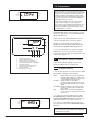
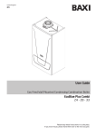
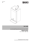
United Kingdom
en
User Guide
Condensing Boiler with Integrated Hot Water Storage
Promax Store
24
Please keep these instructions in a safe place.
If you move house, please hand them over to the next occupier.
Natural Gas
Contents
Potterton Promax 24 Store ErP
G.C.No 41 592 47 (90 litre)
G.C.No 41 592 48 (115 litre)
G.C.No 41 592 49 (150 litre)
Section
Page
1.0
Quick Reference Guide
3
2.0
Troubleshooting
4
IMPORTANT
3.0
Repressurising System
6
Please read and understand all these instructions before commencing installation.
Please leave this manual with the customer for future reference.
4.0
Clearances
7
5.0
Care of the Boiler
8
6.0
Legislation
9
7.0
Programmer
10
8.0
Warranty & Service
14
9.0
ErP Information
16
Advice to Users
Promax Store provides domestic hot water from a
high performance, high efficiency version of a
traditional storage cylinder. Whenever hot water is
used it is replaced by fresh cold water and, provided
this occurs when the programmer is in a ‘DHW ON’
period, the boiler will operate to raise it to the
temperature you have selected. This will take from a
few minutes to around 20 minutes, depending on how
much hot water has been drawn from the storage
cylinder. Please adjust the time and temperature
settings on the programmer according to your
experience of the boiler’s performance and your
household’s need for hot water.
10.0 Notes
20
11.0 Emergency
23
12.0 Disposal
23
The Benchmark Scheme
Baxi Heating UK Ltd is a licensed member of the Benchmark Scheme which aims to
improve the standards of installation and commissioning of domestic heating and hot
water systems in the UK and to encourage regular servicing to optimise safety,
efficiency and performance.
Benchmark is managed and promoted by the Heating and Hotwater Industry Council.
For more information visit www.centralheating.co.uk
© Baxi Heating UK Ltd 2015 All rights reserved. No part of this publication may be
reproduced or transmitted in any form or by any means, or stored in any retrieval
system of any nature (including in any database), in each case whether electronic,
mechanical, recording or otherwise, without the prior written permission of the
copyright owner, except for permitted fair dealing under Copyrights, Designs and
Patents Act 1988.
Applications for the copyright owner’s permission to reproduce or make other use of
any part of this publication should be made, giving details of the proposed use, to the
following address:
The Company Secretary, Baxi Heating UK Ltd,
Brooks House, Coventry Road, Warwick. CV34 4LL
Full acknowledgement of author and source must be given.
WARNING: Any person who does any unauthorised act in relation to a copyright work
may be liable to criminal prosecution and civil claims for damages.
0086
ISO 9001
FM 00866
2
© Baxi Heating UK Ltd 2015
1.0 Quick Reference Guide
Promax HE Store
2
1
3
4
0
bar
ON/OFF/Reset
Selector Switch
Display
Central Heating
Temperature Control
Domestic Hot Water
Temperature Control
Programmer
System
Pressure Gauge
OFF Position
Central Heating & Hot Water
Hot Water
Reset
The boiler will not operate.
Both Heating & Hot Water will operate.
Hot Water only will operate.
Hold for approx 5 seconds and release.
Central Heating Indicator - The indicator will illuminate when the boiler is in the
central heating mode.
Domestic Hot Water Indicator - The indicator will illuminate when hot water is
being supplied to a tap or shower.
Burner On Indicator - The indicator will illuminate when the burner has fired and is
heating your central heating or domestic hot water.
Boiler Output Temperature - In either the central heating or domestic hot water
position the display will illuminate showing the current boiler temperature in
degrees centigrade.
Central Heating Temperature Control
Turn the knob clockwise to increase or anticlockwise to decrease the
temperature. Range 25° C to 80° C.
Domestic Hot Water Temperature Control
Turn the knob clockwise to increase or anticlockwise to decrease the temperature.
Range approximately 45° C to 65° C.
2
1
3
Central Heating System Pressure - The normal operating water pressure is
between 1 and 2.0 bar. If the pressure exceeds 3 bar the safety pressure valve will
operate and a fault is indicated. Contact your Installer.
4
0
bar
© Baxi Heating UK Ltd 2015
3
Boiler not working
2.0 Troubleshooting
START
Make sure the gas supply
YES
is turned ON and check if
other gas appliances are
operating (e.g. fire, cooker).
Is the ON/OFF/Reset
Select Switch in the
(
) position ?
Is the (
) or (
) light
on and the (
) on ?
YES
Domestic Hot
Water Indicator
Central Heating
Indicator
NO
NO
If no gas, consult your
supplier.
Is the display lit ?
Burner On
Indicator
YES
Boiler operating satisfactorily.
Display
NO
Check electricity to the
boiler is switched on.
Is the Central Heating
System Pressure between
1 and 2.5 bar ?
YES
Does the display show an
error code e.g. E133, E110 ?
NO
NO
2
1
3
4
0
bar
If the reading falls below 1 bar
repressurise the system as
described in section 3.0.
YES
Turn the ON/OFF/Reset
Selector Switch to Reset.
If boiler does
not Reset
Error Code E119 showing
low pressure.
4
© Baxi Heating UK Ltd 2015
2.0 Troubleshooting
Is the Integral Programmer
ON and calling for heat ?
M
RUN
CLOCK
HW PROG
CH PROG
T
W
T
F
S
S
YES
Is the Room Thermostat (if
fitted) set high enough ?
10
HW CH
15
20
5
25
AUTO
AM
YES
ALL DAY
24 HR
ON
CH
HW
SET
OFF
ADVANCE
BOOST
ADVANCE
HW
CH
_
+
ENTER
COPY
NO
Ensure programmer is set for
Central Heating ON or Hot
Water ON (see section 7.4 for
setting the programmer).
Turn Room Thermostat to
maximum setting (typical
example shown).
15
20
25
5
10
CONTACT YOUR
INSTALLER OR
SERVICE ENGINEER.
If you don’t know what you need to do
to get the boiler to light, or need help
with the system and controls, contact
your installer as soon as possible.
© Baxi Heating UK Ltd 2015
5
3.0 Repressurising System
3.1
Central Heating System Pressure
2
1
3
1. The normal operating water pressure is
between 1 and 2.5 bar (Fig. 1). If the pressure
exceeds 3 bar the safety pressure valve will
operate and a fault is indicated. Contact your
installer.
4
0
bar
Normal Pressure
Fig. 1
2. It may be necessary to repressurise the system
occasionally (Fig. 2). A filling device (the filling
loop) is fitted on the boiler itself.
2
1
3
3. The filling loop consists of two taps and a
separate metal braided hose pipe.
4
0
bar
4. Only when repressurising should the hose be
connected between the two taps. No tools are
necessary for this, but ensure that the wing nuts
on the hose pipe ends are tightened onto the
taps.
Requires
Repressurising
Fig. 2
5. Fully open one of the taps first, and then while
watching the pressure gauge, carefully open the
second tap.
6. When the needle on the gauge is indicating 1
or more, turn both taps off.
7. Disconnect the hose from the taps (a small
amount of water may be present) and remove it.
Keep the hose in a safe place for future use.
Promax Store
RWC
Filling Loop
6
© Baxi Heating UK Ltd 2015
25mm
25mm
4.0 Clearances
250mm
4.1
For your Safety
This appliance must have been installed in
accordance with the manufacturer’s instructions
and the regulations in force.
Any modification that may interfere with the
normal operation of the appliance without
express written permission from the manufacturer
or his agent could invalidate the appliance
warranty. In GB this could also infringe the Gas
Safety (Installation and Use) Regulations.
GB - Heating Industry definition meaning England,
Scotland, Wales, Northern Ireland, Isle of Man and
the Channel Isles
Your boiler must not be operated without the
casing correctly fitted and forming an adequate
seal.
Do not interfere with any sealed components on
this boiler.
Take note of any warning labels on your boiler.
Your boiler should have the following minimum
clearances for Safety and Maintenance
(Fig. 4 & 5):Top
Left side
Right Side
Front
Fig. 4
- 250mm
- 25mm
- 25mm
- 50mm (In Operation)
- 450mm (For Servicing)
If your boiler is installed in a compartment, do not
use it for storage purposes. Do not obstruct any
purpose provided ventilation openings.
Flammable materials must not be stored in close
proximity to your boiler.
Avoid skin contact when your boiler is in
operation, as some surfaces may get hot i.e.
pipework, flue.
Ensure that the flue terminal, outside the house,
does not become damaged or obstructed,
particularly by foliage.
450mm
for Servicing
purposes
It is important that the condensate drain system
is not blocked, modified or damaged in any way
as this would affect the operation of your boiler.
Your installer should have insulated any exposed
pipework.
50mm
In operation
Fig. 5
© Baxi Heating UK Ltd 2015
7
5.0 Care of the Boiler
5.1
Cleaning the Outercase
1. The painted panels should be wiped with a
damp cloth and then dried completely. DO NOT
USE ABRASIVE CLEANING AGENTS.
5.2
Protection & Precautions
1. The boiler incorporates an integral frost
protection feature that will operate in both modes.
If the boiler temperature falls below 4° C, the
boiler will fire until a temperature of 15° C is
reached.
2. If a system frost thermostat has been fitted
(your installer will be able to advise you), then to
operate correctly and protect your system, the
gas and electricity must be left on and the
appliance set in the central heating mode.
3. The boiler incorporates an integral pump
protection feature which monitors the time since
the pump last operated and will operate the
pump for approximately 1 minute if it has not run
in the last 24 hours.
8
© Baxi Heating UK Ltd 2015
6.0 Legislation
6.1
Installation, Commissioning, Service & Repair
1. This appliance must be install in accordance with the
manufacturer’s instructions and the regulations in force.
Read the instructions fully before installing or using the
appliance.
2. In GB, this must be carried out by a competent person
as stated in the Gas Safety (Installation & Use) Regulations.
3. Definition of competence: A person who works for a
Gas Safe registered company and holding current
certificates in the relevant ACS modules, is deemed
competent.
4. IN IE (Eire), this must be carried out by a competent
person as stated in I.S. 813 “Domestic Gas Installations”.
Lifting - This product should be lifted and handled by two
people. Stooping should be avoided and protective
equipment worn where necessary. Carrying & lifting
equipment should be used as required, e.g. when installing
in a loft space.
All Gas Safe registered engineers carry an ID card with their
licence number and a photograph. You can check your
engineer is registered by telephoning 0800 408 5500 or
online at www.gassaferegistered.co.uk
The boiler meets the requirements of Statutory Instrument
“The Boiler (Efficiency) Regulations 1993 No 3083” and is
deemed to meet the requirements of Directive 92/42/EEC
on the energy efficiency requirements for new hot water
boilers fired with liquid or gaseous fuels:Type test for purpose of Regulation 5 certified by:
Notified Body 0085.
Product/Production certified by:
Notified Body 0086.
For GB/IE only.
6.2
Benchmark Commissioning Checklist
Please ensure that the installer has fully completed the
Benchmark Checklist on the inside back pages of the
installation instructions supplied with the product and that
you have signed it to say that you have received a full and
clear explanation of its operation. The installer is legally
required to complete a commissioning checklist as a
means of complying with the appropriate Building
Regulations (England and Wales).
All installations must be notified to Local Area Building
Control either directly or through a Competent Persons
Scheme. A Building Regulations Compliance Certificate will
then be issued to the customer who should, on receipt,
write the Notification Number on the Benchmark Checklist.
This product should be serviced regularly to optimise its
safety, efficiency and performance. The service engineer
should complete the relevant Service Record on the
Benchmark Checklist after each service.
The Benchmark Checklist may be required in the event of
any warranty work.
© Baxi Heating UK Ltd 2015
9
Fig. 7
1
3
M
RUN
CLOCK
HW PROG
CH PROG
2
T
W
7.0 Programmer
4
T
F
S
S
7.1
HW CH
ALL DAY
24 HR
ON
OFF
ADVANCE
5
CH
HW
1
2
3
4
5
6
7
8
9
10
Introduction
AUTO
AM
BOOST
ADVANCE
HW
CH
SET
_
+
ENTER
COPY
6
7
8
9
10
1. The built-in programmer is an electronic 7-day
central heating and hot water control, designed to be
easy to use and understand. Properly programmed it
will help you save energy and create a comfortable
environment in your home.
2. For convenience, morning and evening ON/OFF
periods have been pre-set in the programmer ‘memory’
and will be retained, even if the mains power supply is
interrupted. Details of these ON/OFF periods are given
in the next section, together with step-by-step setting
instructions.
3. In run mode, any combination can be set (using the
ENTER and COPY buttons) e.g.
Set Indicator
Set Positions
Time of Day
Day of Week Indicator
ON/OFF Switch Period Symbol
SET Button
Minus (-) Adjust Button
Plus (+) Adjust Button
ENTER Button
COPY Button
Hot Water Programme
AUTO
4. The Promax programmer also offers the following
features :
*
Up to 3 On-Off time periods every 24 hours plus
the option of programming different times for each
day of the week.
*
A central heating ADVANCE button allowing an
instant switch from OFF to ON or ON to OFF
without affecting normal settings.
*
A hot water BOOST button giving an extra one hour
period.
THE RECOMMENDED COMBINATION IS :
Hot Water Programme
ALL DAY
C/Heating Programme
AUTO
or ALL DAY
or 24 HOUR (Continuous)
or OFF
C/Heating Programme
AUTO
The display should then look like this :
7.2
Fig. 8
M
RUN
CLOCK
HW PROG
CH PROG
T
W
T
F
S
S
Buttons, Indicators & Symbols
HW CH
AUTO
AM
ALL DAY
24 HR
OFF
Most of the control buttons on the programmer are dual
purpose. They can be used as SET buttons for inputting
time of day. ON/OFF times, etc, or as SELECT buttons
for using the advance facility and choosing override
programme options.
Figure 7 can be used to identify the SET buttons,
indicators and symbols.
7.3
Setting the Programmer
1. Turn the appliance selector switch to central heating
and hot water position.
2. Setting Day and Time
NOTE: When setting the day, time of day or switch
times, if a period exceeding 60 seconds is allowed
to elapse between button presses, the programmer
will automatically return to normal RUN mode and
any changes made since the last press of the
ENTER button will not be saved.
Fig. 9
M
RUN
CLOCK
HW PROG
CH PROG
T
W
T
F
S
S
HW CH
AUTO
AM
ALL DAY
24 HR
i) Press the SET button so that the SET INDICATOR is
pointing to the CLOCK position on the front of the
programmer. the DAY OF THE WEEK INDICATOR will
now flash (see Fig. 9).
OFF
10
© Baxi Heating UK Ltd 2015
7.0 Programmer
Fig. 10
M
RUN
CLOCK
HW PROG
CH PROG
T
W
T
F
S
S
HW CH
AUTO
AM
ALL DAY
24 HR
ii) Use the PLUS (+) or MINUS (-) to move the DAY OF
THE WEEK INDICATOR to the current day of the week.
Numbers relating to the day of the week are printed
along the top of the programmer display, ie
1=Monday,
2=Tuesday and so on.
OFF
iii) Press the ENTER button. The TIME OF DAY will now
flash (Fig. 10).
iv) Now use the (+) or (-) BUTTONS to alter the display
to the correct time of day making sure that the AM/PM
SYMBOL is also correct (FIG. 11).
Fig. 11
M
RUN
CLOCK
HW PROG
CH PROG
T
W
T
F
S
S
HW CH
AUTO
NOTE: By pressing and releasing the (+) or (-)
buttons you advance or retard the time in 1 minute
steps. If you keep the button depressed the display
will fast cycle and the time can be changed more
rapidly.
ALL DAY
PM
24 HR
OFF
v) Press the ENTER button. Now use the SET BUTTON
to return the SET INDICATOR to the RUN POSITION.
7.4
Setting ‘ON’ & ‘OFF’ Times
NOTE: The minimum ON or OFF period that can be
set is ten minutes.
1. The integral programmer already has a factory preset suite of ON/OFF times in its memory. These are:
Fig. 12
M
T
W
T
F
S
S
AUTO
ALL DAY
M
T
W
T
F
S
S
2. If these settings do not meet your own requirements
then they can be easily changed as follows:
OFF
AUTO
iii) Adjust the flashing time as required by using the (+)
and (-) buttons then press ENTER. The display will now
show ‘1 OFF’ and the first programmed OFF time for
the day will flash (see Fig. 14).
ALL DAY
24 HR
T
W
AM
T
F
S
S
i) Press the SET BUTTON twice so that the SET
INDICATOR is in a PROG position (HW or CH). The
display will indicate the ‘day’ and the DAY OF THE
WEEK INDICATOR will now flash.
ii) Use the (+) or (-) BUTTONS to move the indicator to
the day of the week that you wish to change the times
for. Press ENTER. The display will show ‘1 ON’ and
then first ON time for that day will flash (see Fig. 13).
AUTO
AM
M
RUN
CLOCK
HW PROG
CH PROG
Central Heating
1st ON
1st OFF
7.30 am
10.30 am
2nd ON
2nd OFF
12.00 pm
12.00 pm
3rd ON
3rd OFF
4.30 pm
11.30 pm
HW CH
ON
Fig. 14
Saturday / Sunday
Hot Water
1st ON
1st OFF
7.00 am
10.30 am
2nd ON
2nd OFF
12.00 pm
1.00 pm
3rd ON
3rd OFF
4.00 pm
11.30 pm
24 HR
OFF
RUN
CLOCK
HW PROG
CH PROG
Central Heating
1st ON
1st OFF
6.30 am
9.00 am
2nd ON
2nd OFF
12.00 pm
12.00 pm
3rd ON
3rd OFF
5.00 pm
11.00 pm
HW CH
RUN
CLOCK
HW PROG
CH PROG
Fig. 13
Monday to Friday
Hot Water
1st ON
1st OFF
6.00 am
9.00 am
2nd ON
2nd OFF
12.00 pm
12.00 pm
3rd ON
3rd OFF
4.30 pm
11.00 pm
HW CH
ALL DAY
24 HR
OFF
OFF
iv) This can now be altered in the same way as the
‘1 ON' time mentioned above.
v) Follow the same procedure for the 2nd and 3rd
ON/OFF times remembering to press ENTER after each
change to the programme. If you do not wish to alter a
particular time then simply press ENTER and the
display will move on to the next ON/OFF time leaving
the previous one unchanged.
© Baxi Heating UK Ltd 2015
11
7.0 Programmer
Fig. 15
M
T
W
T
F
S
S
HW CH
RUN
CLOCK
HW PROG
CH PROG
AUTO
ALL DAY
24 HR
OFF
NOTE: The programmer provides up to three ON/OFF
periods each day. If you do not want to use all these, a
switch period can be cancelled by programming the ON
operation for the same time as the OFF operation e.g.
2nd ON at 12.00 pm and 2nd OFF at 12.00 pm. When
the 3rd OFF time has been entered the programmer will
display the word COPY and the DAY OF THE WEEK
INDICATOR will flash (see Fig.15).
If required these ON/OFF times can now be quickly
copied so that they apply to any other day(s) you
choose. This avoids separately programming days with
identical switching times eg Monday to Friday. If not
copying press ENTER and press SET button to return
SET INDICATOR to run position.
vi) Use the (+) and (-) BUTTONS to move the DAY OF
THE WEEK INDICATOR to the next day that you wish
the times to apply and press the COPY BUTTON, the
display will indicate ‘IN’.
Fig. 16
M
RUN
CLOCK
HW PROG
CH PROG
T
W
T
F
S
S
HW CH
AUTO
AM
Continue in this way until the programme has been
copied to all the days that you wish it to apply to.
ALL DAY
24 HR
OFF
ADVANCE
CH
HW
BOOST
ADVANCE
_
SET
+
HW
ENTER
vii) When you have finished copying simply press
ENTER. The word COPY will be replaced with ‘day’
and the DAY OF THE WEEK INDICATOR will flash.
CH
COPY
3. You can now programme those days that require
different times to the ones you have just copied by
following the same procedure as described at the start
of this section, parts ii to v.
10
1
2
3
4
5
6
7
8
9
10
Hot Water ON Indicator
Central Heating ON Indicator
Advance Button - Central Heating
Hot Water Programme Select Button
Central Heating Programme Select Button
Programme Positions
Central Heating Programme Indicator
Hot Water Programme Indicator
Advance Indicator
Boost Button - Hot Water
7.5
Select Buttons, Indicators & Symbols
1. The following diagram (Fig.16) can be used to
identify the SELECT buttons and indicators.
7.6
Programme Selection
1. The following programmes can be selected for either
HOT WATER or HEATING or both together.
AUTO:
When AUTO is selected the programmer
will switch ON and OFF according to the
switching times held in the memory, ie up
to three ON/OFF periods per day.
ALL DAY: When ALL DAY is selected the
programmer will switch the system on at
the 1st ON TIME and OFF at the 3rd OFF
TIME.
24 HOURS: When 24 HOUR is selected the system
remains on continuously, ignoring all the
time settings.
OFF:
When OFF is selected the programmer
clock continues to operate but the system
remains off.
Fig. 17
M
RUN
CLOCK
HW PROG
CH PROG
T
W
T
F
S
S
HW CH
AUTO
AM
ALL DAY
24 HR
OFF
2. To select a hot water programme press the HW
PROGRAMME SELECT BUTTON until the HW (HOT
WATER) PROGRAMME INDICATOR is pointing to the
required programme, e.g. ALL DAY (see Fig. 17)
3. To select a central heating programme follow the
same procedure using the CH PROGRAMME SELECT
BUTTON.
NOTE: When either HOT WATER or HEATING is
switched to ON the relevant INDICATOR LIGHT will
be illuminated (see Fig.16).
12
© Baxi Heating UK Ltd 2015
7.0 Programmer
7.7
Fig. 18
M
RUN
CLOCK
HW PROG
CH PROG
T
W
T
F
S
S
Using the Advance and Boost Button
HW CH
AUTO
AM
ALL DAY
24 HR
ADVANCE
1. The ADVANCE facility allows you to bring forward the
next heating ON or OFF period without having to alter
the programmed ON/OFF times.
OFF
2. Press the ADVANCE BUTTON once and release. The
word ADVANCE will appear in the display (see Fig.18).
3. If the programmer was originally ON it will now switch
OFF and stay OFF until the next programmed ON time.
4. The opposite will apply if the programmer was
originally OFF.
Fig. 19
5. In both cases the unit will then revert to the normal
programme times.
M
RUN
CLOCK
HW PROG
CH PROG
T
W
T
F
S
S
HW CH
AUTO
AM
ALL DAY
24 HR
ON
CH
HW
SET
OFF
ADVANCE
BOOST
ADVANCE
HW
CH
_
+
ENTER
COPY
6. If you wish to cancel the advance simply press the
ADVANCE BUTTON again and the word ADVANCE will
disappear from the display.
NOTE: The ADVANCE facility has no effect when the
CH PROGRAMME INDICATOR is in either the 24
Hour or the OFF position.
7. Pressing the BOOST button during an
unprogrammed time for hot water will give a one hour
period of hot water operation.
7.8
Programmer Faults
1. Electronic equipment can, in exceptional
circumstances, be affected by electrical interference. If
the display or switching programme becomes frozen or
scrambled, or you wish to revert to the factory pre-set
programme, you can RESET the programmer by
pressing the MINUS (-) adjust button and the
ENTER/HW SELECT BUTTON together (see Fig. 19).
2. After using the RESET procedure you will need to
reprogramme the day and time of day plus any changes
you wish to make to the factory pre-set programme.
3. The programmer is not user serviceable. DO NOT
ATTEMPT TO DISMANTLE IT.
4. In the unlikely event of it developing a fault, contact
your Gas Safe Registered Installer or Service Engineer,
but before doing so try the RESET PROCEDURE above.
5. Should a replacement programmer be required your
Installer can obtain this as Part No. 5117092.
7.9
Reserve Battery
1. The programmer is fitted with a NONRECHARGEABLE LONG LIFE battery which will
maintain the programmed ON/OFF settings for a period
in excess of 2 years (Part No. 5118231).
2. This is more than sufficient to cover all the expected
power interruptions during the life of the unit.
NOTE: If a power interruption of more than 48 hours
occurs the ‘time of day’ will need to be re-adjusted
once the power is restored.
© Baxi Heating UK Ltd 2015
13
8.0 Warranty & Service
8.1
General
To make sure your boiler warranty is activated and
maintained, it is essential that the:
1. Benchmark checklist is completed by your installer
2. Warranty is registered with Baxi
3. Boiler has an annual service
Please note that failure to adhere to terms and
conditions will make your warranty invalid.
8.2
Terms of Warranty
8.2.1
Standard Warranty Terms and Conditions
Warranty Registration, Service & Repair
For full terms and conditions, visit
www.baxi.co.uk/terms.
Benchmark Checklist
The Benchmark Checklist will be completed by your
installer and records that the boiler has been installed
and commissioned correctly. It can be found at the back
of the installation and service manual and should be
kept in a safe place for the life of the boiler. We will
check that the Benchmark Checklist has been
completed on an in-warranty visit.
Ways to register your warranty
If your boiler is eligible for an extended warranty, your
installer may register the product on your behalf and
provide you with the relevant documentation. Please
check with your installer.
Should this not be the case, you can register your
warranty online at www.baxi.co.uk/registration
To activate a standard two year warranty, please use
one of the following methods:
• Freephone 0800 013 7989 or
• Return the enclosed registration card
14
8.0 Warranty & Service
Annual Service
A service must be completed every 12 months from the
date of installation to maintain your warranty.
This service must be completed by one of the following:
• A Gas Safe registered installer/engineer
• Baxi Customer Support; call us
0344 871 1525
Please make sure that your engineer has logged the
service information at the back of the installation and
service manual. You will be asked for your service
history on any in-warranty repair visit.
If you experience a problem with your boiler
For any in or out of warranty repair, Baxi Customer
Support is on hand to help you. Call our award-winning
team to arrange for one of our nationwide team of Gas
Safe registered engineers to visit.
If your product is in warranty, everything is free of
charge, subject to our warranty terms and conditions. If
it is out of warranty, we can still help and offer a range of
options you can choose from to suit your needs.
Contact Baxi Customer Support
0344 871 1525
Opening hours
Monday - Friday, 8.00am - 6.00pm
Weekends and Bank Holidays, 8.30am - 2.00pm
Please note calls may be recorded for training and
monitoring purposes.
When contacting Baxi Customer Support, please have
the following information to hand:
• Boiler serial number. This can be found on the
appliance.
• Proof of purchase if you do not have the boiler
serial number.
Please note that for in-warranty repairs, our engineers
will ask to see your service history record, completed
Benchmark Checklist and details of your installer. These
can all be found in the installation and user manual.
15
9.0 ErP Information
9.1
Product Fiche - Boiler Space Heaters
Product fiche for combination boilers
Potterton Promax 24 Store ErP
90
115
150
Medium
Medium
Medium
XL
XL
XL
Seasonal space heating energy efficiency class
A
A
A
Water heating energy efficiency class
A
A
B
Space heating - Temperature application
Water heating - Declared load profile
Rated heat output (Prated or Psup)
kW
24
24
24
Space heating - Annual energy consumption
kWh
GJ
20870
75
20870
75
20870
75
Water heating - Annual energy consumption
kWh
GJ
16
16
19
Seasonal space heating energy efficiency
%
92
92
92
Water heating energy efficiency
%
90
92
77
Sound power level LWA indoors
dB
57
57
57
See
For specific precautions about assembling, installing and maintaining,
consult the relevant section as detailed on the Contents page.
16
© Baxi Heating UK Ltd 2015
9.0 ErP Information
Package Fiche - Boilers
9.2
Package fiche for boilers indicating the space heating energy efficiency of the package
Seasonal space heating energy efficiency of boiler
1
‘I’
Temperature control
from fiche of temperature control
Class I = 1%, Class II = 2%, Class III = 1.5%,
Class IV = 2%, Class V = 3%, Class VI = 4%,
Class VII = 3.5%, Class VIII = 5%
Supplementary boiler
Seasonal space heating energy efficiency (in %)
%
2
+
%
3
from fiche of boiler
(
- ‘I’ ) x 0.1 = ±
Solar contribution
%
(1)
Tank rating
from fiche of solar device
Collector size (in m²)
(‘III’ x
Tank volume (in m³)
+
A* = 0.95, A = 0.91,
B = 0.86, C = 0.83,
D - G = 0.81
Collector efficiency (in
%)
‘IV’ x
) x
0.9 x (
/100)
x
4
= +
%
(1) If tank rating is above A, use 0.95
Supplementary heat pump
Seasonal space heating energy efficiency (in %)
5
from fiche of heat pump
(
- ‘I’ ) x ‘II’ = +
%
Solar contribution AND Supplementary heat pump
4
select smaller value
0.5 x
5
0.5 x
OR
6
= -
Seasonal space heating energy efficiency of package
%
7
%
Seasonal space heating energy efficiency class of package
G
F
E
D
C
B
A
+
A
++
A
+++
A
<30%
Boiler and supplementary heat pump installed with low temperature heat emitters at 35°C ?
7
from fiche of heat pump
+ (50 x ‘II’) =
%
The energy efficiency of the package of products provided for in this fiche may not correspond to its actual energy efficiency once installed
in a building, as this efficiency is influenced by further factors such as heat loss in the distribution system and the dimensioning of the
products in relation to building size and characteristics.
AD-3000743-01
I
II
© Baxi Heating UK Ltd 2015
The value of the seasonal space heating energy efficiency of the
preferential space heater, expressed in %.
The factor for weighting the heat output of preferential and supple
mentary heaters of a package as set out in the following table.
17
9.0 ErP Information
Package Fiche - Boilers (cont)
9.2
III
I
IV
V
The value of the mathematical expression: 294/(11 ʷ Prated),
whereby ‘Prated’ is related to the preferential space heater.
The value of the mathematical expression 115/(11 ʷ Prated),
whereby ‘Prated’ is related to the preferential space heater.
Weighting of boilers
Psup / (Prated + Psup)(1)(2)
II, package without hot water storage tank
II, package with hot water storage tank
0
0
0
0.1
0.3
0.37
0.2
0.55
0.70
0.3
0.75
0.85
0.4
0.85
0.94
0.5
0.95
0.98
0.6
0.98
1.00
≥ 0.7
1.00
1.00
(1) The intermediate values are calculated by linear interpolation between the two adjacent values.
(2) Prated is related to the preferential space heater or combination heater.
Package efficiency
90
Potterton Promax 24 Store ErP
18
Temperature control X
%
Temperature control Y
%
115
150
© Baxi Heating UK Ltd 2015
9.0 ErP Information
9.3
Package Fiche - Combination Heaters
(Boilers or Heat Pumps)
Package fiche for combination heaters (boilers or heat pumps) indicating the water heating energy efficiency of the
package
Water heating energy efficiency of combination heater
1
‘I’
%
Declared load profile:
Solar contribution
Auxiliary electricity
2
from fiche of solar device
(1.1 x ‘I’ - 10%) x ‘II’ -
‘III’
- ‘I’ = +
Water heating energy efficiency of package under average climate
%
3
%
Water heating energy efficiency class of package under average climate
G
F
E
D
C
B
A
+
A
++
A
+++
A
M
L
XL
XXL
<28%
Water heating energy efficiency under colder and warmer climate conditions
3
2
- 0.2 x
Colder:
3
Warmer:
=
%
=
%
2
+ 0.4 x
The energy efficiency of the package of products provided for in this fiche may not correspond to its actual energy efficiency once installed
in a building, as this efficiency is influenced by further factors such as heat loss in the distribution system and the dimensioning of the
products in relation to building size and characteristics.
AD-3000747-01
I
II
III
© Baxi Heating UK Ltd 2015
The value of the water heating energy efficiency of the combination
heater, expressed in %.
The value of the mathematical expression (220 ʷ Qref)/Qnonsol,
where Qref is taken from Regulation EU 811/2013, Annex VII Table
15 and Qnonsol from the product fiche of the solar device for the de
clared load profile M, L, XL or XXL of the combination heater.
The value of the mathematical expression (Qaux ʷ 2,5)/(220 ʷ Qref),
expressed in %, where Qaux is taken from the product fiche of the
solar device and Qref from Regulation EU 811/2013, Annex VII Ta
ble 15 for the declared load profile M, L, XL or XXL.
19
10.0
20
Notes
10.0
Notes
21
10.0
22
Notes
11.0
Emergency
Warning !
If you smell gas
Do not operate light switches
Do not operate any electrical equipment
Do not use a telephone in the hazardous area
Extinguish any naked flame and do not smoke
Open windows and doors in the hazardous area
Turn off the gas supply at the meter
Warn any other occupants and vacate the premises
Telephone the National Gas Emergency Service on:0800 111 999
Faulty boiler
If it is known or suspected that a fault exists
on the boiler, it must not be used until the fault
has been corrected by a competent person.
-
+
H.W. TEMP
POWER
MAINS ON
BURNER
LOCK OUT
RESET
C.H. ADVANCE
SEL
+
SEL
PROG
-
PROG
Gas
Cock
(0pen)
In an Emergency
RWC
22mm Gas
Connection
Fig. 20
MAX0023C
1. Turn off the electrical supply and turn the
selector switch on the facia box to the OFF
position.
2. Using a suitable open ended spanner or
screwdriver turn the square on the gas tap to the
left to isolate the gas supply (Fig. 20).
3. Call your Installer or Service Engineer as soon as
possible.
12.0
12.1
Disposal
Disposal and Recycling
NOTE: Removal and disposal of the boiler must
be carried out by a qualified person in accordance
with local and national regulations.
© Baxi Heating UK Ltd 2015
23
Baxi Customer Support
0344 871 1525
Opening hours
Monday - Friday, 8.00am-6.00pm
Weekends and Bank Holidays, 8.30am-2.00pm
Please note calls may be recorded for training and monitoring purposes
baxi.co.uk
Register now to activate your warranty:
www.baxi.co.uk/registration
For the warranty to be maintained, please make sure...
1
2
3
Benchmark checklist is completed
Warranty is registered with Baxi
The boiler has an annual service
For full terms and conditions, visit www.baxi.co.uk/terms. Failure to adhere to
terms and conditions will void your manufacturer’s warranty.
Baxi
Brooks House,
Coventry Road,
Warwick, CV34 4LL
0086
Please ensure the boiler is installed in accordance with these installation
instructions and that you adhere to the Building Regulations.
e&oe
All descriptions and illustrations provided in this document have been
carefully prepared but we reserve the right to make changes and
improvements in our products which may affect the accuracy of the
information contained in this leaflet. All goods are sold subject to our
standard Conditions of Sale which are available on request.
7221757 - 01 (04/15)
part of