1
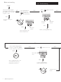
You can rely on
User’ Guide and
Important Warranty Information
Performa 30 HE
Condensing
Combination Boiler
These instructions include the Benchmark Commissioning
Checklist and should be left with the user for safe keeping.
© Baxi Heating UK Ltd 2009
Contents
Section
Natural Gas
Potterton Performa 30 HE
G.C.No 47 393 13
Where fitted, user label for
optional timer to be applied here
Page
1.0
Quick Reference Guide
3
2.0
Troubleshooting
4
3.0
Fault Indication
6
4.0
System Pressure & Temperature
7
5.0
Clearances
8
6.0
Care of the Boiler
9
7.0
Legislation
10
8.0
Emergency
11
9.0
Warranty & Service
12
The Benchmark Scheme
Baxi Heating UK Ltd is a licensed member of the Benchmark Scheme which aims
to improve the standards of installation and commissioning of domestic heating
and hot water systems in the UK and to encourage regular servicing to optimise
safety, efficiency and performance.
Benchmark is managed and promoted by the Heating and Hotwater Industry
Council. For more information visit www.centralheating.co.uk
© Baxi Heating UK Ltd 2009 All rights reserved. No part of this publication may
be reproduced or transmitted in any form or by any means, or stored in any
retrieval system of any nature (including in any database), in each case whether
electronic, mechanical, recording or otherwise, without the prior written
permission of the copyright owner, except for permitted fair dealing under
Copyrights, Designs and Patents Act 1988.
Applications for the copyright owner’s permission to reproduce or make other
use of any part of this publication should be made, giving details of the proposed
use, to the following address:
The Company Secretary, Baxi Heating UK Ltd, The Wyvern Business Park,
Stanier Way, Derby, DE21 6BF.
Boiler Controls - see opposite page
for Operating Quick Reference Guide
Full acknowledgement of author and source must be given.
WARNING: Any person who does any unauthorised act in relation to a
copyright work may be liable to criminal prosecution and civil claims for damages.
0086
ISO 9001
FM 00866
2
© Baxi Heating UK Ltd 2009
1.0 Quick Reference Guide
2
Reset
1
3
4
0
bar
ON/OFF/Reset
Selector Switch
Indicator
Neons
Central Heating
Temperature Control
Reset
Domestic Hot Water
Temperature Control
Reset
System Pressure Gauge
Reset
Position of
Optional Timer
Reset
OFF Position
Central Heating & Hot Water
Domestic Hot Water
Reset
The boiler will not operate.
Both Heating & Hot Water will operate.
Hot Water will operate.
Hold for approx 5 seconds and release.
30° 40° 50° 60° 70° 80°
Power On Indicator - The indicator will illuminate when there is power to the
boiler.
Domestic Hot Water Indicator - The indicator will illuminate when hot water
is being supplied to a tap or shower.
Boiler On - The indicator will illuminate when there is a demand for heat to
the boiler.
Burner On Indicator - The indicator will illuminate when the burner has fired
and is heating your central heating or domestic hot water.
Indicator
Neons
Central Heating Temperature Control
Turn the knob clockwise to increase or anticlockwise to decrease the
temperature. Range 35 - 85° C (± 5°C).
Domestic Hot Water Temperature Control
Turn the knob clockwise to increase or anticlockwise to decrease the
temperature. Range 35 - 65° C (± 5°C).
2
1
3
4
0
Central Heating System Pressure - The normal operating water pressure is
between 1 and 2.0 bar. If the pressure exceeds 3 bar the safety pressure valve
will operate and a fault is indicated. Contact your Installer.
bar
© Baxi Heating UK Ltd 2009
3
Boiler not working
2.0 Troubleshooting
START
Make sure the gas supply is
turned ON and check if other
gas appliances are operating
(e.g. fire, cooker).
YES
Is the (
(
) on ?
YES
Is the ON/OFF/Reset
Select Switch in the
(
) position and
the Power ON indicator
lit ?
) light on and the
NO
30° 40° 50° 60° 70° 80°
NO
If no gas, consult your
supplier.
30° 40° 50° 60° 70° 80°
Reset
Boiler On
Indicator
Burner On
Indicator
YES
NO
Power On
Indicator
Boiler operating satisfactorily.
Check electricity to the
boiler is switched on.
Is the Central Heating System
Pressure needle in the GREEN
section, between 1 and 2.5 bar ?
YES
Is the (
NO
) indicator neon on ?
NO
30° 40° 50° 60° 70° 80°
Flame Failure
Neon
2
1
3
4
0
bar
If the reading falls below 1 bar
repressurise the system as
described in section 4.1.
YES
Turn the ON/OFF/Reset
Selector Switch to Reset.
Reset
4
© Baxi Heating UK Ltd 2009
If boiler does not
Reset
2.0 Troubleshooting
Is the Timer ON and calling for
heat ?
12
Is the Room Thermostat (if
fitted) set high enough ?
10
15
20
25
4
8
5
3
9
2
5
6
7
Typical
examples of
external timer
YES
1
10
11
YES
CH ON
CH OFF
NO
Turn Room Thermostat to
maximum setting (typical
example shown).
NO
5
10
15
20
25
Ensure timer is set for Central
Heating ON (see any
instructions supplied with
timer).
CONTACT YOUR
INSTALLER OR
SERVICE ENGINEER.
If you don’t know what you need to do to
get the boiler to light, or need help with
the system and controls, contact your
installer as soon as possible.
© Baxi Heating UK Ltd 2009
5
3.0 Fault Indication
3.1
NOTE: The neons annotated have a dual function, indicating the temperature of the
central heating water when constantly illuminated or begin to flash to indicate a fault.
Air Flow
Monitor Neon
Pump/Low
Pressure Neon
Safety Thermostat
Neon
Flame
Failure
Neon
Sensor Fault
Neons
Air Flow Monitor
1. The boiler is fitted with an air pressure sensing device. This
monitors the flue system.
2. If the (
) neon illuminates it indicates that the flue or
flue terminal is blocked or obstructed in some way, or that
there is an internal fault. If there is no external blockage of the
flue terminal that can be easily removed contact your Installer
or Service Engineer (Fig. 1).
3.2
Pump Fault or Low Pressure
30° 40° 50° 60° 70° 80°
1. The neon (
) will illuminate if the circulating pump is
faulty or the system pressure drops below the minimum
requirement (Fig. 1).
Fig. 1
2. Check the pressure gauge as described on page 8. If the
pressure is in the normal range, a pump fault is indicated.
Contact your Installer or Service Engineer to determine the
nature of the fault.
3.3
Sensor Fault
1. When either of the (
) or (
) neons is illuminated a
fault on one of the temperature sensors is indicated (Fig. 1).
Contact your Installer or Service Engineer.
3.4
Pump Protection
1. With the selector switch in the on position (Fig. 2) the
pump will automatically operate for 1 minute in every 24
hours to prevent sticking.
3.5
Reset
Safety Thermostat
1. Your Potterton Performa HE is fitted with an additional
safety devices, which shut down the boiler in the event of the
system, boiler or flue overheating. The safety thermostat neon
( ) will light in this instance (Fig. 1).
3.6
Flame Failure
Fig. 2
1. The red flame failure neon (
) will illuminate in the event
of the burner failing to light, when incomplete lighting of the
burner occurs or blockage of the condensate drain (Fig. 1).
Reset
Fig. 3
3.7
To Reset the Safety Thermostat or Flame
Failure
1. To reset: Turn the selector fully anti-clockwise against the
spring pressure to the ‘Reset’ position for at least two seconds
and release (Fig. 3).
2. If after turning the selector to the ‘Reset’ position the boiler
does not relight or the safety thermostat or flame failure
operates repeatedly, causing boiler shutdown, a fault is
indicated. Your Installer or Service Engineer should be
contacted as soon as possible.
6
© Baxi Heating UK Ltd 2009
4.0 System Pressure & Temperature
2
4.1
1
3
1. The normal operating water pressure is between 1 and 2.5
bar (Fig. 4). If the pressure exceeds 3 bar the safety pressure
valve will operate and a fault is indicated (Fig. 6). Contact your
installer.
4
0
bar
Fig. 4
2. It may be necessary to repressurise the system occasionally
(Fig. 5). A filling device (the filling loop) will be fitted on the
system. If you are unsure of its position, or cannot identify it,
consult the installer who fitted the boiler.
Normal Pressure
2
1
3. The filling loop will probably consist of two taps and a
separate metal braided hose with connection fittings.
3
4. Only when repressurising should the hose be connected
between the two taps. Ensure that the nuts on the pipe ends
are tightened onto the taps.
4
0
Central Heating System Pressure
bar
Fig. 5
Requires
Repressurising
5. Fully open one of the taps first, and then while watching the
pressure gauge, carefully open the second tap.
2
6. When the needle on the gauge is indicating 1 or more turn
both taps off.
1
7. Disconnect the metal braided hose from the taps (a small
amount of water may be present) and remove it. Keep the
hose in a safe place for future use.
3
4
0
bar
Fig. 6
4.2
Temperature Control
Fault
1. Central Heating: The central heating hot water flow
temperature can be adjusted between 30° C (± 5° C)
minimum and 85° C (± 5° C) maximum.
2. Turn the control knob clockwise to increase the
temperature (Fig. 7). In normal winter usage we recommend
that the central heating temperature be set at maximum.
3. Domestic Hot Water: The temperature of the domestic
hot water can be adjusted by turning the control knob
clockwise to increase up to a maximum of 65°C (Fig. 8).
4. The temperature of the water is also dependent on the
water flow rate and the temperature of the mains coming into
the house.
5. By slightly reducing the flow from the tap the temperature
will increase up to the maximum if required.
6. The flow rate can be reduced down to as low as 2.5
litre/min. The boiler will still recognise the need to heat the
water.
Fig. 7
Central Heating
Temperature Control
© Baxi Heating UK Ltd 2009
Fig. 8
Domestic Hot Water
Temperature Control
7
5.0 Clearances
450mm
5mm Min
20mm/5mm Min
see *NOTE:
5.1
For your Safety
1. This appliance must have been installed in accordance
with the manufacturer’s instructions and the regulations
in force.
200mm Min
2. Any modification that may interfere with the normal
operation of the appliance without express written
permission from the manufacturer or his agent could
invalidate the appliance warranty. In GB this could also
infringe the Gas Safety (Installation and Use) Regulations.
GB - Heating Industry definition meaning England, Scotland,
Wales, Northern Ireland, Isle of Man and the Channel Isles
3. Your boiler must not be operated without the casing
correctly fitted.
780mm
4. Do not interfere with any sealed components on this
boiler.
5. Take note of any warning labels on your boiler.
6. Your boiler should have the following minimum
clearances for Safety and Maintenance
(Fig. 34):-
200mm Min
Top
Bottom
Left side
Right Side
Front
- 200mm
- 200mm
- 5mm
- 5mm
- 5mm (In Operation)
- 450mm (For Servicing)
*NOTE: The boiler can be operated with a clearance
of 5mm at the right. This is also sufficient for routine
maintenance. However a clearance of 20mm is
required if it is necessary to remove the secondary
heat exchanger. This should be considered when
siting the appliance and in the event of any
subsequent alteration in the area of installation.
7. If your boiler is installed in a compartment, do not use
it for storage purposes. Do not obstruct any purpose
provided ventilation openings.
8. Flammable materials must not be stored in close
proximity to your boiler.
450mm Min
For Servicing
Purposes
9. Avoid skin contact when your boiler is in operation, as
some surfaces may get hot e.g. pipework.
10. Ensure that the flue terminal, outside the house,
does not become damaged or obstructed, particularly
by foliage.
11. It is important that the condensate drain system is
not blocked, modified or damaged in any way as this
would affect the operation of your boiler. Your installer
should have insulated any exposed pipework.
5mm Min
In Operation
8
© Baxi Heating UK Ltd 2009
6.0 Care of the Boiler
6.1
Cleaning the Outer case
The painted panels should be wiped with a damp cloth and
then dried completely. DO NOT USE ABRASIVE
CLEANING AGENTS.
6.2
Protection & Precaution
1. The boiler incorporates an integral frost protection feature
that will operate when the selector switch is in the (
)
position. If the boiler temperature falls below 5° C, then the
boiler will operate until the water temperature has been
raised.
2. If a system frost thermostat has been fitted (your installer
will be able to advise you), then to operate correctly and
protect your system, the gas and electricity must be left on and
the appliance set in the central heating mode.
3. The boiler incorporates an integral pump protection feature
which continually monitors the time since the pump last
operated. To prevent seizure, the pump will operate for
approximately 1 minute if it has not run in the last 24 hours.
6.3
To Shut Off the Boiler (Fig. 9)
1. For short periods: Turn the selelctor switch to the Off
position.
2. For long periods: Turn off the selector switch, electricity
and gas supplies.
Reset
OFF Position
(Selector Switch)
Fig. 9
© Baxi Heating UK Ltd 2009
If your home is to be left unoccupied for long periods
during cold weather the boiler and whole system should be
drained unless there is additional frost protection.
3. Your installer will advise you about frost protection and
draining the system.
9
7.0 Legislation
7.1
Installation, Commissioning, Service & Repair
1. This appliance must be install in accordance with the
manufacturer’s instructions and the regulations in force. Read
the instructions fully before installing or using the appliance.
2. In GB, this must be carried out by a competent person as
stated in the Gas Safety (Installation & Use) Regulations.
3. Definition of competence: A person who works for a Gas
Safe registered company and holding current certificates in the
relevant ACS modules, is deemed competent.
4. IN IE (Eire), this must be carried out by a competent person
as stated in I.S. 813 “Domestic Gas Installations”.
All Gas Safe registered engineers carry an ID card with their
licence number and a photograph. You can check your
engineer is registered by telephoning 0800 408 5500 or online
at www.GasSafeRegistered.co.uk
The boiler meets the requirements of Statutory Instrument
“The Boiler (Efficiency) Regulations 1993 No 3083” and is
deemed to meet the requirements of Directive 92/42/EEC on
the energy efficiency requirements for new hot water boilers
fired with liquid or gaseous fuels:Type test for purpose of Regulation 5 certified by:
Notified Body 0051.
Product/Production certified by:
Notified Bodies 0051 & 0086.
For GB/IE only.
7.2
Benchmark Commissioning Checklist
1. Please ensure that the installer has fully completed the
Benchmark Checklist on the inside back pages of the
installation instructions supplied with the product and that you
have signed it to say that you have received a full and clear
explanation of its operation. The installer is legally required to
complete a commissioning checklist as a means of complying
with the appropriate Building Regulations (England and Wales).
2. All installations must be notified to Local Area Building
Control either directly or through a Competent Persons
Scheme. A Building Regulations Compliance Certificate will
then be issued to the customer who should, on receipt, write
the Notification Number on the Benchmark Checklist.
3. This product should be serviced regularly to optimise its
safety, efficiency and performance. The service engineer should
complete the relevant Service Record on the Benchmark
Checklist after each service.
4. The Benchmark Checklist may be required in the event of
any warranty work and as supporting documentation relating
to home improvements in the optional documents section of
the Home Information Pack.
10
© Baxi Heating UK Ltd 2009
8.0 Emergency
Warning !
If you smell gas
Turn off the gas supply at the meter and call your gas
supplier immediately. It is possible to isolate the boiler at
the isolating valve (Fig. 10).
In GB, Transco operate a 24 hour emergency service and
the telephone number will be listed in your telephone
directory.
Faulty boiler
If it is known or suspected that a fault exists
on the boiler, it must not be used until the fault
has been corrected by a competent person.
In an Emergency
If a water or gas leak occurs or is suspected, the boiler can
be isolated at the inlet valves as follows;
1. Using a suitable open ended spanner, turn the square
nut on the gas tap through 90° (1/4 turn) to isolate the gas
supply at the boiler (Fig. 10).
Gas Tap
2. The water isolating valves are positioned under the
boiler and can be closed by turning their taps to the right
towards the wall (Fig. 10).
3. Call your Installer or Service Engineer as soon as
possible.
Fig. 10
Heating Flow and
Heating Return Isolating
Valves
© Baxi Heating UK Ltd 2009
11
Please complete the boxes below
9.0 Warranty & Service
Serial Number
Standard Warranty Term & Conditions
12 Months Free Warranty - register today
To receive your 12 months free warranty please complete the form supplied
with the boiler or simply call heateam, the service of Baxi Heating UK Ltd on
0800 731 1644.
Date of Installation
D D M M Y Y
Installer Details (name, address and contact number(s))
Our promise to you
If you experience a fault with your new boiler, we aim to provide a safe and
high quality repair service supported by our dedicated national network of
highly skilled engineers. If your installer can’t resolve the problem for you, we
will do everything we can to get an engineer out to you as quickly as possible.
Nothing in this warranty will affect your statutory consumer rights.
What you need to do if you experience a problem with your heating system
or the operation of the boiler
You should always contact your installer first, because the fault may not be
related to the boiler. If your installer confirms that the fault is within the boiler
it self and he/she can’t repair it, our friendly customer service team is on hand
to help. Simply call our service division heateam on 0844 871 1560 to book an
engineer visit or for any general advice that you may need. Our contact centre
is open Monday to Friday 8am - 6pm, weekends and Bank Holidays 8.30am 2pm, excluding Christmas Day and New Years Day.
When calling heateam it would be helpful if you could have the following
information to hand:1
2
3
4
boiler serial number (see opposite).
boiler make and model number.
Your installer name and address details.
Proof of purchase (if you do not have the boiler serial number).
What this warranty covers
Free of charge repair or replacement of components found to be faulty from
manufacture.
Free of charge replacement of the complete unit provided always that the
failure is related to a manufacturing fault that cannot be repaired or is
uneconomic to repair.
The warranty runs for 12 months from the date your product is installed.
What this warranty does not cover
Repairs to boilers which haven’t been installed and commissioned properly,
and as set out in the installation instructions (this includes the need to flush the
system effectively and add a suitable corrosion inhibitor).
Any damage caused by hard water scale deposits and/or aggressive water
resulting from corrosion.
Any other defects or failures, either in the connected heating system or
outside of the boiler itself.
Faults caused by inadequate supply of electricity, gas or water to the property.
Information Label
Installations within commercial settings for which this boiler was not designed.
All descriptions and illustrations provided in this leaflet have been carefully
prepared but we reserve the right to make changes and improvements in
our products which may affect the accuracy of the information contained in
this leaflet. All goods are sold subject to our standard Conditions of Sale
which are available on request.
Reimbursement of any third party repair or replacement costs that we haven’t
been told about or agreed with you in advance.
P O T T E RTON
Annual Service
To ensure you receive the maximum efficiency from your boiler we
recommend your boiler has an annual service so you and your family can
continue to enjoy heating and hot water comfort.
To arrange an annual service from one of our Baxi Heating UK Ltd heating
experts, please call 0844 871 1545.
A Tr a din g D i v i s i on of B a x i Heat i ng U K Lt d ( 3879156)
A D ivis io n of B a x i Gro u p
Brooks House, Coventry Road, Warwick. CV34 4LL
After Sales Service 0844 871 1560 Technical Enquiries 0844 871 1555
Website www.potterton.co.uk
e&oe
© Baxi Heating UK Ltd 2009
Compensation for consequential losses (e.g. loss of earnings, business losses,
stress and inconvenience) arising from a production breakdown, including
repair delays caused by factors outside our reasonable control.
UK Comp No 5111816 - Iss 7 - 7/09