1
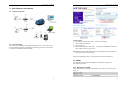
iBaby Monitor User Manual Index 1 iBaby Monitor Model: M3 2 3 4 User Manual INTRODUCTION................................................................................................................ 4 1.1 THE PACKAGE CONTENTS .............................................................................................. 4 1.2 FUNCTION AND FEATURES ............................................................................................. 4 1.3 PRODUCT SPECIFICATION .............................................................................................. 5 APPEARANCE AND INTERFACE .................................................................................... 6 2.1 APPEARANCE ............................................................................................................... 6 2.2 INTERFACE OF THE CAMERA .......................................................................................... 7 VISIT CAMERA FROM LOCAL AREA NETWORK .......................................................... 7 3.1 LOCAL AREA NETWORK CONNECTION ............................................................................ 7 3.2 VISIT CAMERA WITH A IPOD TOUCH, IPHONE AND IPAD..................................................... 8 3.3 SEARCH AND SET THE IP ADDRESS OF THE CAMERA ........................................................ 8 3.4 VISIT CAMERA FROM A PC .......................................................................................... 10 VISIT CAMERA OVER INTERNET ................................................................................. 13 4.1 INTERNET CONNECTION ............................................................................................... 13 4.2 PORT FORWARDING .................................................................................................... 13 4.3 DDNS ....................................................................................................................... 14 4.3.1 Manufacturer’s DDNS ........................................................................................... 14 4.3.2 Third Party DDNS ................................................................................................. 15 5 "This product is meant for providing convenience for baby OTHER SETTINGS.......................................................................................................... 15 5.1 NETWORK SETTING..................................................................................................... 15 5.1.1 Basic Network Setting ........................................................................................... 15 monitoring. The manufacturer is not responsible for any legal 5.1.2 WIFI Setting .......................................................................................................... 15 5.1.3 ADSL Setting ........................................................................................................ 16 liability caused by negligence. " 5.1.4 UPnP Setting ........................................................................................................ 16 5.1.5 DDNS Setting ....................................................................................................... 17 5.1.6 MSN Setting .......................................................................................................... 17 5.2 ALARM SETTINGS ....................................................................................................... 17 5.2.1 Alarm Setting ........................................................................................................ 17 5.2.2 Mail Service Setting .............................................................................................. 19 5.2.3 FTP Service Setting .............................................................................................. 20 5.2.4 Alarm Server ......................................................................................................... 21 5.3 ADVANCED ................................................................................................................. 21 5.3.1 User Setting .......................................................................................................... 21 5.3.2 Multi Device Setting .............................................................................................. 22 5.3.3 Other settings ....................................................................................................... 22 5.4 MAINTAIN.................................................................................................................... 23 2 iBaby Monitor User Manual 5.4.1 Device Information ................................................................................................ 23 5.4.2 Time Setting .......................................................................................................... 23 5.4.3 Firmware upgrade ................................................................................................. 24 5.4.4 Restore Factory Default ........................................................................................ 24 5.4.5 User browsing Log ................................................................................................ 24 6 CENTRALIZATION CONTROL....................................................................................... 24 7 FAQ .................................................................................................................................. 25 iBaby Monitor User Manual 1 Introduction The iBaby monitor combines a high quality digital video camera with network connectivity and a powerful web server to bring clear video to your iPod Touch, iPhone and iPad, or a PC from anywhere on your local network or over the Internet. 1.1 The package contents Camera * 1 User Manual & Utility CD *1 Power Adapter *1 Bracket * 1 Cable * 1 Antenna * 1 Quick Installation Guide *1 Screw *1 set 1.2 Function and Features Support 802.11b/g protocol, can build up wireless monitoring. It adopts the TCP/IP network protocols and has inner web server. Users can browse video with a iPod Touch, iPhone and iPad, also can browse video through IE and other browsers. With built-in Microphone, it enables user to monitor the sound on the site. User can also connect this camera to a speaker, and it supports two-way intercom function. It was equipped with pan/tilt function, horizontally 350°and vertically 70°. Its outlook is smart, easy and convenient to install in many sites. Infrared LED for night vision covers 5m area, to realize 24 hours monitoring. Motion detection, sound detection and alarm pin can be connected to external sensors to detect environmental situation. Alarming record can be stored by email, FTP server. External alarm can be open when detecting something unusual. Supports UPNP, port forwarding automatically on the router. Manufacture attaches a label at the bottom of each Camera, providing free DDNS. When Camera is connected to the internet, this DDNS can be used to visit the camera. Manufacture provides free PC software, support Multi-view, Long time recording, video replay etc. 3 4 iBaby Monitor User Manual iBaby Monitor User Manual Power 1.3 Product Specification Item Image Capture Pan/Tilt Assistant Video and Audio Network Other Features Hardware Interface Physical Index Sub Item Description Sensor CMOS sensor Total of pixel 300k Minimum illumination 0 Lux(IR on automatically) Lens f=3.6mm, F=2.0, Fixed Iris Pan Coverage 350° Tilt Coverage 70° Lighting 10pcs 850nm Infrared LEDs, 5m distance Lighting Control Auto control Resolution 640*480(VGA)/320*240(QVGA)/1 60*120(QQVGA) Compression MJPEG Frame rate 30fps Bit rate 128kbps ~ 5Mbps Image Rotation Mirror /Flip Software(iPod Touch , iPhone and iPad) ADPCM Basic Protocol Other Protocol 802.11b/g Video control Support Dual way audio Support Motion Detection Support Support Triggered Actions User Access Authority Three levels Date/ Time Setting Support Upgrade Upgrade from network DDNS A free DDNS provided by manufacturer Ethernet 10Base-T/100base-TX Alarm In 1 channel Alarm Out 1 channel Audio In Internal Mic and External Mic socket x 1 Audio Out Audio Line-out socket x 1 Weight 358g Main body 111mm(L)*110mm(W)*126mm(H) 0℃~ 40℃ Operating humidity 10% ~ 80% non-condensing iOS 4.0 or later App is free to download from App Store OS Supported Microsoft Windows 98/2000/XP/Vista/Win 7 etc. Mac OS Browser Internet Explorer6.0 or higher, or Compatible Browser, Firefox, Safari etc. Application Software IPCMonitor.exe 2 Appearance and interface TCP/IP、UDP/IP、HTTP、SMTP、 FTP、DHCP、DDNS、UPNP、NTP、 PPPOE Email/FTP/external alarm/send message to alarm server <6W Operating temperature Software(PC) Audio Compression Sound Detection DC 5V Power consumption 2.1 Appearance Figure 1 Note:Status Indicator: the blue light is to show that the device is running. Slow flicking (once every 2 second)indicates the device is searching for network. Normal flicking (once per second) indicates the wired network connected. Quick flicking(2~3 times per second) indicates wireless network connected. The default state of status indicator is off. You can turn it on with your iPod Touch, iPhone and iPad, or PC software. 5 6 iBaby Monitor User Manual iBaby Monitor User Manual 2.2 Interface of the camera Figure 4 3.2 Visit camera with a iPod Touch, iPhone and iPad Figure 2 Prior to using you must first install the iBaby Monitor App from the App Store. THIS IS A FREE DOWNLOAD. Please confirm the iOS is V4.0 or later. If not, update your iOS before using this product. If you have not install that, please launch the App Store, and search using the keyword “iBaby Monitor”, be sure your web function is enabled. 1) Power Input Socket: Connect Power adaptor, the adaptor‘s output is 5V 1.5A. 2) RESET Button: Press the RESET button and hold on more than 10 seconds, the camera will restart and recover to the factory default settings. 3) WIFI Antenna Connector: Install the WIFI antenna. 4) RJ45 Ethernet Socket: RJ45 Ethernet socket is 10/100M self-adjust. 5) Audio Input Socket: Audio input socket is designed for connecting external microphone. The built-in microphone will be invalidation when the external microphone plug in. . Launch the iBaby Monitor App, it will automatically search the camera in your local area network, and follow the instruction on the App, you can set up the camera easily. After downloading, a icon should be appeared like this: 6) Audio Output Socket: Audio output socket is for line-out audio player, such as headphone, speaker, etc. 7) Alarm Output Socket 8) Alarming Input Pin 3.3 Search and set the IP address of the camera Run “BSearch_en.exe” in the CD, the setting interface as figure 5. 3 Visit Camera from Local Area Network 3.1 Local Area Network connection Figure 3 7 8 iBaby Monitor User Manual iBaby Monitor User Manual Figure 6 3.4 Visit Camera from a PC We suggest using IE kernel browser to view the video (it can provide more functions), but user need to install Player before viewing the video. Click “download and install player (first use)” link, it will popup dialogue box as Figure 7, click Run, it will automatically download player and install. Figure 5 Operation Steps: 1) Click “Search (F3). 2) Choose the device. 3) Change the ip address of the camera according to the information in the red frame on the left. The numbers in the red circle should not be the same. 4) Put the user name and password into “Authentication” (By default, the user name is: admin, password is: 123456). 5) Click “Update”. 6) After successfully update, click “Search (F3)”, choose the device and click “Browse (F4)”. Then you may view the camera, like figure 6. NOTE: 1) If you don’t know how to fill out the content of “IP config”, you could also tick the “Set IP automatically” to get the IP address from the router automatically. 2) If you have the firewall software in your PC, when you run the BSearch_en.exe, it may pop up a window to say “whether you want to block this program or not”, then you should choose not to block. Figure 7 After install the plug-ins, click “Mode 1 to view” link in Figure 6 to view the video (video as Figure 8). 9 10 iBaby Monitor User Manual iBaby Monitor User Manual Figure 9 4) PT and video control In Pan/Tilt control area, user can control the position according to the arrow sign: up, down, left, right, middle, horizontal cruise, vertical cruise, and stop etc. Means open IO output and Close IO output. Figure 8 1) Main Menu The main menu includes the function setting of different submenu 2) Status Displaying Area In right up corner, it is the status displaying area, to show the 9 devices’ status: if not connected, button is gray if connected, button is green If wrong connected , button is yellow If alarm , button is red 3) Multi Channel displaying area If users add multi channel(refer to 5.3.2), when shift to 4-Ch, 9-CH, and it will automatically show other devices. You select one device, and you can operate it by these keys: play, stop, and record, control Pan/tilt, etc. User can also set the device frame rate、resolution, brightness, contrast and other parameters. These buttons mean start video, stop, monitor, talk, record and snapshot. P.S: If you want to click this button to record the video, please go to advanced—Other Settings to set the Record Path first. Please see below figure9. 11 12 iBaby Monitor User Manual iBaby Monitor User Manual 4 Visit Camera over Internet 4.1 Internet connection Figure 11 Operation Steps: 1) After login the interface of the router,choose “Port Forwarding” 2) Choose “Add custom Service” 3) Input camera port. 4) Input camera IP address,click “Apply”。(the http port and ip address should be the same as figure 5 which set by you own) Figure 10 4.2 Port forwarding Now most router have UPNP, and the UPNP default status is on, so you need not to do the port forwarding. Otherwise, you must do port following on the router If visit Camera over internet. Take Netgear router for example. Note: Different router has different settings for port-forwarding; please kindly follow your router guide to do the port-forwarding. After the port-forwarding is done, you could view the IP Camera from WAN now. 4.3 DDNS You could also use the manufacturer DDNS to view the device as long as your port-forwarding succeeds. 4.3.1 Manufacturer’s DDNS Device manufacturer has provided a free DDNS. User can find it in network menu, like figure 12. 13 14 iBaby Monitor User Manual iBaby Monitor User Manual Figure 12 4.3.2 Third Party DDNS User can also use third part DDNS, such as www.3322.org. User must apply a free domain name from this website and fill the info into the below blanks (Figure 13) and save the settings. Then the domain name can be used. Figure 13 Note: Using the third party domain name, if the http port is not 80, the port number should be adding to the domain name with colon. Example: http://btest.3322.org:81. While manufacturer DDNS is no need to add PORT. 5 Other Settings Figure 15 Note1: When the device is connected both WIFI and wired, it will firstly connect to the wired network, if it can’t connect to it, then it will change to connect to the wifi. The IP address and port is the same, either wireless or wired network. Note2: Before you do the configuration of wireless as shown above; please make sure the device is connected to the network via network cable. After settings succeed, please reboot the device and wireless function takes effect. 5.1.3 ADSL Setting User could enable the ADSL Dialup according to the below Figure 16 (The ADSL provider will assign the user name and password to you when you apply for ADSL service.) Connect the device directly to the ADSL modem and it is connected to the Internet. 5.1 Network Setting 5.1.1 Basic Network Setting The user can also enter the Basic Network Settings to set the IP address except using the search software. See below Figure 14. Figure 14 5.1.2 WIFI Setting Figure 16 If the device is with WIFI, enter the Wireless LAN Setting, just as below Figure 15 shown, click the “Scan” button, it will show you all the wireless networks detected in the Wireless Network List column. Select one of them and tick “Using Wireless Lan”, then the relevant data of the selected wireless network will be shown in the following blanks. Put in the password and click “Set”, then the WIFI setting is finished. 5.1.4 UPnP Setting If you enable UPNP, once the IP camera is connected into the LAN, it will communicate with the router in the LAN to do the port-forwarding automatically. Below Figure 17, tick “Using UPNP to Map Port” and the setting are completed. You could check the UPNP succeeds or not in the interface of System Maintenance. Figure 17 Before using UPNP function, please make sure the router’s UPNP function has been triggered. Not all the routers support UPNP perfectly. Please test if the router works well 15 16 iBaby Monitor User Manual with the equipment, if not, we would suggest you to disable this function and do the port-forwarding manually. iBaby Monitor User Manual The user can select voice detection, triggering the alarm. The more the figure, and the more sensitive. 5.1.5 DDNS Setting Please refer to the content in 4.3. 5.1.6 MSN Setting Figure 19 Figure 18 User needs to apply for a MSN account for this device first, for example: [email protected]. Please put this MSN account and its password as above Figure 18. Then put your MSN account, for example: [email protected], into the ‘MSN Friends List. Then on your [email protected] MSN list, you can see [email protected] is online. You just send “url?” to [email protected] and you will get the WAN ip address of this ip camera. But please make sure [email protected] and [email protected] should be MSN friends before you do the settings. 2) Alarm Action All kinds of alarm modes: IO interface for alarm signal output: when relay is switched on, the external alarm will begin to alarm. Send alarm info by email. Send the site pictures to the FTP server, user can also set the break time between two pictures. Send alarm info to the alarm server. 3) Scheduler Device will trigger alarm in scheduled time. User can set schedule time to be “all the time”. Before you set “Schedule”, please go to Date and Time settings to set the correct time for the item, as shown in figure 20. 5.2 Alarm Settings 5.2.1 Alarm Setting 1) Alarm Detect User can select the motion detection. If there is any motion, it will detect the motion and trigger the alarm. In the motion detect sensibility, the more the figure, and the more sensitive. As showed in Figure 19, if any external alarm detector is connected, user will be able to tick “Alarm Input Armed”. If the external alarm detector is an always on switch alarm, please choose “open”. If the external alarm detector is always off switch alarm, please choose “close”. 17 18 iBaby Monitor User Manual iBaby Monitor User Manual Figure 21 Figure 20 5.2.2 Mail Service Setting 5.2.3 FTP Service Setting The device will send alarm email to you. You only need to fill out the blanks with your email address as shown in Figure 21. After the setting, please click save and test to check if it works properly. If it is properly set, user can tick to enable “Report Internet IP by mail”. After every restart, the device will send its Internet IP address to user’s email address. Figure 22 When alarming, device will snap and send the image to FTP server, please make sure the FTP setting is correct. Above Figure 22 of FTP setting for your reference, after the setting is finished, click “Test” to test your settings are correct or not. After correct setting FTP server, you can use “upload Image Periodically” function. Even no alarm, device can also send the snap image to FTP periodically. In order to use FTP function, user should apply username and password on the FTP 19 20 iBaby Monitor User Manual server first. And please apply some storage, and the authority to write and create sub-category into it. iBaby Monitor User Manual 5.3.2 Multi Device Setting 5.2.4 Alarm Server Figure 23 Please confirm if you have connected to alarm server. The alarm message format as follow: GET /api/alarm.asp? username=username& userpwd=password& rea=alarm type (1=Motion Detection, 2 =Alarm from Alarm in port)& io=0 Alarm server needs developing by user. User can extend other functions on this server, like SMS, MMS alarm, and mobile phone etc. 5.3 Advanced 5.3.1 User Setting There are three levels of authority; they are Administrator/Operator/Visitor. Administrator have the highest authority, it can do any change to the settings. Operator account only can operate the IP camera, can’t do changes to the settings. Visitor account only can watch the video, can’t do any operation to the IP camera. By default, the administrator’s user name is admin, password: 123456. Figure 25 As Figure 25, User can maximum add 9 devices to view the device simultaneously. Click refresh button to check the device in the LAN. When click the device, will popup setting dialogue box and input the device info, as figure 26 and click save. After that, must click submit button to save. Figure 26 5.3.3 Other settings You can choose open or close indicator LED. If set PTZ center on start ‘Yes’, when start device, Pan/Tilt will move to center and then stop. You can also set the Horizon patrol rounds and vertical patrol rounds, when you click patrol on the ‘view’ interface, it will round according to your setting rounds. You can also set PTZ rate, 0 means fastest. Figure 24 21 22 iBaby Monitor User Manual iBaby Monitor User Manual 5.4.3 Firmware upgrade The device runs 2 kinds of programmer, one is system firmware, the other is application firmware. They could be upgraded separately. Figure 30 5.4.4 Restore Factory Default Click “Restore Factory Default”, it will pop up a dialogue to confirm if you really want to restore the factory default. After confirmation, the system will restore the factory default and reboot. Figure 27 5.4.5 User browsing Log 5.4 Maintain After enter the log interface, you could view who and when the device is visited. 5.4.1 Device Information Figure 31 6 Centralization Control This is a free software offered by factory, several devices on LAN and WAN can be browsed at the same time. The software also supports snap, video record, alarm and so on. The below Figure 32 is the interface. Figure 28 5.4.2 Time Setting If the device is connected to the Internet, you enable the NTP server to correct the time and select the right time zone. Or you should use the PC’s time to correct its time. Figure 29 23 24 iBaby Monitor User Manual iBaby Monitor User Manual change them on the same Network Segment before visit. Network Segment is the first three number of IP address. If the IP address of PC is 192.168.0.100, so it can only visit the equipment which IP address is between 192.168.0.1~192.168.0.255. 6) Can visit via public IP address, but can’t visit via manufacturer’s domain name Make sure the DNS setting is same as your PC, as below Figure 33, in the search tool, the DNS 1 and DNS 2 on both side should be same. Figure 32 For more information, pls. refer to the <<English IPC Monitor User Manual>> in CD. 7 FAQ 1) Figure 33 Unmatched power adapter will damage the equipment or power adapter When plug in the power adapter, please check carefully the voltage, it should be 5V adapter for this equipment. 2) Slowly browse speed This equipment adopts MJEPG compression format, it needs large network bandwidth, the narrow bandwidth will affect the browse speed. The typical bandwidth uses situation as below: 640x480@10fps : 4.0 Megabits ~ 5.0 Megabits 320x240@30fps : 1.2 Megabits ~ 1.6 Megabits 3) Color difference The default is infrared lens, when visit outdoor or strong infrared light scenes, there are color differences, the color is not accordance to the real scenes. User can change it to color lens to solve this problem, but color lens can only use under the daylight situation. 4) Can’t find equipment via search software after connect to LAN Make sure the equipment and PC is in the same LAN; if install firewall software, please close it and try again. 5) Can find equipment via search software, but can’t visit If the IP address of camera and PC is not in the same Network Segment, you should 25 26 INDEX IP Camera Centralization Management Client Application (IPCMonitor) May, 2011 Version 1.3 User Manual 1 Introduction ........................................................................................................ 3 2 Computer Requirement ...................................................................................... 3 3 Installation .......................................................................................................... 3 4 Device Management .......................................................................................... 4 5 6 4.1 Adding A Device .......................................................................................... 4 4.2 Adding Multiple Devices in LAN ................................................................... 6 4.3 Modifying Devices........................................................................................ 6 4.4 Deleting Device............................................................................................ 7 4.5 Further Notifications for Device List Window ................................................ 7 Video view.......................................................................................................... 7 5.1 Start the Video ............................................................................................. 8 5.2 Alarm Trigger ............................................................................................... 8 5.3 Video Recording Trigger .............................................................................. 9 5.4 Stop the Video ............................................................................................. 9 Device Control.................................................................................................... 9 6.1 Base Operation ............................................................................................ 9 6.2 Device Control Panel ................................................................................. 10 7 Channel Management ...................................................................................... 10 8 Other Settings .................................................................................................. 11 9 8.1 System Setting .......................................................................................... 11 8.2 History Log ................................................................................................ 12 Further Notifications ......................................................................................... 12 1 Introduction IPCMonitor is a centralization management software provided by the manufacturer. It provides the central control of monitoring, video capture, alarm testing, etc for multiple IP cameras on LAN or WAN. Before using this software, please ensure the devices can be access by web browsers from LAN or WAN, please consult the user manual of the IP Camera to know the IP Camera belongs to which series(support Q/B/H series products). This article provides a how-to on viewing the IP Camera's video by using this dedicated client application. a successful installation, run the application and the user interface will be shown as Figure 1. 4 Device Management The following steps are required before using this application: 1) Plan and install the IP Camera(s) which intend to be monitored. 2) Login to the IP Camera(s) by web browser and set the IP address, port, username & password, alarm setting, system time etc. 3) DDNS setting is a plus whenever you intent to visit the devices by WAN. 2 Computer Requirement In this application, Device Management tab is shown as Figure 2: Using IPCMonitor, your computer should meet the following configuration: CPU: Dual-core CPU RAM: 1GB or above Hard disk: 160GB or above OS: “Windows XP or higher Resolution of display: ≧1024*768 Figure 2: Devices Management 3 Installation 4.1 Adding A Device 1) Basic configuration Figure 3: Adding A Device tab Figure 1: Application User Interface Insert the bundled CD to the drive, double click IPCMonitor, a pop-up window will be shown, please follow the instruction on the window to finish the software installation. After Click the button shown on Figure 2, information of the device will be prompted to input. As of Figure 3: device name is unique (operation will be denied in case name conflicts) in Device Management, and once set, it is recommended not to be changed. Choose the right product series(Required). The fields 'Domain/IP', 'Port', 'Viewing Username', and ‘Viewing Password' are required. Test the connection from web browser. Since the device is connected to WAN, IP address can be instead by a domain name. 2) Alarm Setting Alarm mode can be set by clicking on the Alarm Setting tab, as of Figure 4. Enabling the alarm, check the 'Enabled alarm' first. Figure 5: Record Scheduling 4.2 Adding Multiple Devices in LAN Multiple devices within the LAN can be added by clicking the button. A sample is shown in Figure 6. Select the product series and click “Search”, the found devices will be listed. Tick the checkbox on the device which going to be added, assign a name and set the viewing username and password. Click “OK” , then the device is put in the device list. Figure 4: Alarm Setting Select “All time” or “Schedule armed”,then fill out the Trigger and Action blank. Note: Before alarm setting, please make sure the ip camera’s configuration is correct and it could detect the alarm. (refer to the ip camera user manual) Figure 6: Add Multiple Devices During the armed period, alarm action like siren, snapshot or video recording will be taken once the trigger meets. 3) Record Scheduling Video recording can be scheduled by clicking on the Record Scheduling tab. The device will perform video recording automatically according to the schedule, as of Figure 5. NOTICE: In case a firewall is running on the computer, by the time clicking the “search” button, a window would pop-up asking whether block or unblock the application, please click 'unblock'. 4.3 Modifying Devices Modify the setting of a device by selecting the device and click button. The modifying window is same as 'Adding A Device' window. It can change the device data, alarm setting and record setting. When modifying a device name, click the down arrow and select 'Modify device name' from the drop list. As of Figure 7. 5.1 Start the Video Figure 7: drop list 4.4 Deleting Device Video can be start by the following three methods: Select and double click on a device needed to be started; a free channel will be taken to show up the video. Delete a device by selecting it and click the button. When deleting all the devices, click the down arrow on the right side and select 'delete all devices' from the drop list. 4.5 Further Notifications for Device List Window Select a device and click the button will start it as well. By clicking on the down arrow, start all the devices command can be found on the drop list. Select a device, drag and drop it to a channel, it will show up the video in this channel. Device name will be shown in green on the status bar when it's started. In case the device is offline, or IP address, port, viewing username or password is wrong, the connection could not be established, and related information will be pop-up. 1) After adding a device, right click on the device and select open browser, a browser window will be opened and auto login to the device. In case the login fails, the device 5.2 Alarm Trigger may be offline or the device info is incorrect. 2) A icon will be shown on the right side of a device, in case alarm is enabled. 3) A icon will be shown on the right side of a device, in case video recording is scheduled. 4) If you double click and area, it will pop up the alarm and record setting window. 5) The last column of the list is to display alarm,double click this area,It will present the device’s alarm. 1) After started a video, the application will detect the device to determine if there's any alarm occurred. 2) Whenever an alarm is detected, the application will check the armed time, once the alarm is within an armed time, alarm action will be taken. 3) When a icon twinkling on the device field, means an alarm action is being taken, click on the icon can stop the siren. 4) When a appears but not twinkling, means there was an alarm, double click on the icon will pop-up a recent alarm list. The icon will disappear by closing the alarm list. The alarm list window is as Figure 9. Figure 8 Device list 5 Video view After adding devices, IPCMonitor doesn't work until the related devices are started. IPCMonitor provides the following operation/functions: display the devices video, arm the devices, and decide when to start a scheduled video recording, response to user's command. Figure 9: Alarm List window 5) Even the video alarm recording trigger is set, it will not take any effect in case it is taking a scheduled recording job or capturing a video manually by the time an alarm activated. 6) In case snapshot trigger is set, the file name will be started with an A prefix following by the time stamp as the other part, the suffix is .JPG. 7) Please refer to chapter 8.1 for the option of alarm action. be performed accordingly. 5.3 Video Recording Trigger 1) The application can perform 3 types of video recording , the alarm video recording (set in Figure 4), scheduled recording (set in Figure 5) and manual recording (by clicking on the record button in Figure 10). The manual recording has top priority, scheduled recording takes second, then alarm recording. Example: If a manual recording is initialed by the time an alarm is activated, the application will stop the alarm recording first then start the manual recording. When performing a scheduled video recording, an alarm is activated, the application will not response to the alarm recording request. 2) Prefix of A, M and S will be set to the file name according to alarm recording, manual recording and scheduled recording, time stamp will fill up the other part and ends up with .avi (H series products’ suffix is.asf) 3) Whenever the recording time is longer than one hour for manual recording or scheduled recording, a new file will be created for each hour. 6.2 Device Control Panel Device control panel can be accessed by clicking on 'device control' at the lower right corner or pressing space. 1) You can look up the current channel device information in the Device Control Panel, including: device name and device IP address. 2) The Pan/Tilt can turn up, down, left, right by clicking on the arrows accordingly in the “PTZ Control” area. You also use keyboard to control Pan/Tilt, like as: ← → ↑ ↓; 5.4 Stop the Video A video can be stopped by the following two methods: 1) Select a started device and click the Figure 10: Channel Status Bar Note, the talkback icon is disabled in case another user is utilizing the talkback function. User can only talk to and intercept the sound from the device according to current channel. A window will pop-up after a snapshot, take more snapshot or delete snapshot can be performing within the window. The file name for manual snapshot will start with M, time stamp as the rest, then .JPG as ending. button can stop it's video. All devices can 3) Part of H Series IP Camera, like High Speed Dome , to click control Zoom; can 4) Part of H Series IP Camera, if it has connected a Pan/Tilt, to click: be stopped by clicking on the down arrow and select “stop all video” from the drop list. 2) Right click on a channel and select stop video from the pop-up menu to stop it. 6 Device Control Select a video channel from the display area directly, and you can control the device of this channel. 6.1 Base Operation You will Set/Call the preset; and click auto, the Pan/Tilt will cruise according the preset; and click stop, the Pan/Tilt will stop cruise; 5) A window will pop-up by clicking the 'advanced' button, for the purpose to set up the video compress parameter such as definition, bit rate control, etc 7 Channel Management For the purpose of better video viewing, multiple channel switches are provided. There are switch buttons above the device and channel management panel, shown as Figure 11. 1) Double click on a channel will stretch the video to full screen. By double clicking it again, the video will shrink back to its original size. 2) Click and hold a channel can drag and drop it to another channel, in case the target channel is utilized, the two video channels will swap. 3) By right clicking on a channel, user can perform some operations like stop video, stretch, etc from the pop-up menu. 4) By clicking on the icons in the status bar for each channel, you can snapshot or record manually. Due to different functions, every series product has its own icon content. Status bar of B Series is as Figure 10, it displays the frame rate is 20.5, click these icons, talkback, sound intercepting, snapshot and manual video recording can Figure 11: Channel Switch Buttons The application can provide up to 16 channel videos; it can manage up to 64 devices simultaneously. 8 Other Settings On the top of “Device Management” and “ Device Control”, there are “System Setting”, ”History” and “About” three buttons. Play all the devices when running this software or not Stretch video from all channels or not Hide status bar or not Prompt before shutting down this system or not 8.2 History Log 8.1 System Setting By clicking on the History Log, the video play will be opened, and enter the record directories, user can play the videos sorted by device name. 9 Further Notifications 1) Use administrator to login in your operating system, and then install the ipcmonitor software. 2) Before using this software, please ensure the devices can be access by web browsers from LAN or WAN, please consult the user manual of the IP Camera 3) When performing centralization monitoring, please open Windows Task Manager and check the percentage of CPU usage. If it take more than 80% of CPU usage, the CPU's performance may not be good enough, please refer to the third part in 6.2, click “advanced” and access video setting page to adjust the bitrates or resolution. Figure 12: System Setting System Setting window is shown as Figure 12. Following are some notifications for this window. 1) About alarm settings: In the 'Alarm action settings' section, user can select other sound file (.wav) as siren sound. The default sound will be used in case this field is blank. Users can also configure “Siren Duration, Snapshot Number, Record Duration” data. 2) About storage location:: User can define the picture and video files storage location, leaving this field blank the default location is the application installation directory. Pictures and videos will be stored in. /snap, and. /record directory. If tick “Delete the oldest files When the disk space is insufficient”, when the disk space is less than 500M, this programmer will automatically delete the first day's data and then realize the cycle record function, or it will stop recording. 3) The other options: