1
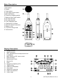
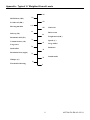
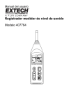
User's Manual
Datalogging Sound Level Meter
Model 407764
Introduction
Congratulations on your purchase of Extech’s Datalogging Sound Level Meter. The meter is capable of
performing all your noise measurements needs in addition to it’s capabilities for data acquisition (direct
data storage to a PC) or datalogging (data storage to internal memory for later download). Data storage
enables the user to save data, analyze data and generate reports. This professional meter, with proper
care, will provide years of safe reliable service.
Safety symbols
Meter is protected throughout by double insulation or reinforced insulation.
CE
Complies with EMC
2
407764-EU-EN-V2.2-5/11
Meter Description
1. Microphone
2. Display
3. Power switch
4. Level range control switch
5. MAX hold switch
6. Frequency weighting switch
7. Response time select switch
8. AC output terminal
9. DC output terminal
10. CAL (calibration) pot.
11. External DC 6V power
12. RS-232 interface connector
13. Battery cover
14. Tripod mounting screw
15. Wind-screen
Display Description
1.
2.
3.
4.
5.
6.
7.
8.
9.
10.
11.
12.
13.
14.
15.
16.
Range selection
Date information
SPL: Instantaneous sound pressure level
Low-Battery
MAX: Maximum SPL value is held
Data recording
Measurement value
Memory full
Units
Frequency weighting (A/C)
TIME function
50dB level (Bargraph)
Over range
SLOW time response
FAST time response
Under range
3
407764-EU-EN-V2.2-5/11
Measurement Preparation
• Read the following safety information before attempting to operate the meter
• Use the meter only as specified or the meter's built-in protection may be impaired.
Maintenance & Cleaning
• Service not covered in this manual should be performed by qualified personnel
• Periodically wipe the case with a dry cloth. Do not use abrasives or solvents.
Battery Replacement
symbol appears on the LCD. Replace batteries
When the battery voltage drops to a critical level, the
as soon as possible after the battery symbol appears. The batteries (4 AA) are located in the rear battery
compartment. Remove the single Philips head screw (center rear) for access to the batteries.
You, as the end user, are legally bound (EU Battery ordinance) to return all used batteries,
disposal in the household garbage is prohibited! You can hand over your used
batteries / accumulators at collection points in your community or wherever batteries /
accumulators are sold!
Disposal: Follow the valid legal stipulations in respect of the disposal of the device at the
end of its lifecycle
Measurements
Default Configuration
1. The meter's default configuration is as follows: 40 to 90dB, 'A' Frequency Weighting, and 'FAST'
Response Time
2. The LCD will reflect the meter's configuration.
Measurement Considerations
1. Use a windscreen to cover the microphone in windy conditions.
2. Calibrate the meter often, especially if the meter has not been used for a long time.
3. Do not store/operate the meter in high temperature/humidity for long periods of time.
4. Keep the meter and the microphone dry.
5. Avoid severe vibration when using the meter.
6. Remove the battery when the meter will be stored for long periods of time.
Frequency Weighting
Change the Frequency Weighting by pressing the 'A/C' button. The 'A' or 'C' icon will display on the right-hand area of
the LCD.
Note: With ‘A’ weighting selected, the meter responds like the human ear (boosting and cutting the noise amplitude over
the frequency spectrum - see Appendix). ‘A’ weighting is used for environmental measurements, OSHA regulatory
testing, law enforcement, and workplace design. Select ‘C’ weighting for flat response measurements (no boost or cut).
‘C’ weighting is suitable for the sound level analysis of machines, engines, etc. Most OSHA related testing is performed
using 'A' Weighting and SLOW Response Time settings.
Response Time
Change the Response Time by pressing the 'FAST/SLOW' button. The 'FAST' or 'SLOW' icon will display on the upper
area of the LCD.
Note: Select FAST to capture noise peaks and noises that occur very quickly. In FAST mode, the meter
responds in 200ms. Select the SLOW Mode (meter responds in 500ms) to monitor a sound source that
has a reasonably consistent noise level or to average quickly changing levels. Selection of Fast or Slow
is determined by the application and any directives or standards related to that application.
Auto/Manual Range
Press the LEVEL button up arrow to scroll through the following ranges: 30-80dB, 40-90, 50-100dB,
60-110, 70-120, 80-130 and 30-130dB (auto). The display will reflect the range for each button press.
Notes: Use Auto Range when the noise source is relatively steady. Use one of the Manual ranges may
be required if the dB levels are changing over a wide range.
4
407764-EU-EN-V2.2-5/11
Operation
1.
2.
3.
4.
Power the meter and select the desired Response Time (Fast or Slow) and Frequency Weighting (A
or C).
Select the desired range.
Hold the instrument comfortably in hand or position on tripod. Point the microphone toward the
noise source, the sound pressure level will be displayed on the meter’s LCD display.
When MAX (maximum hold) mode is selected by pressing the MAX key, the instrument captures
and holds the maximum noise level reading on the display. Press the MAX key again to clear the
MAX reading.
Calibration
Note that a Sound Level Calibrator is required. Set up the meter as listed in Step 1 below.
To calibrate the meter;
1.
2.
3.
4.
Display: SPL (dBA)
Response Time: FAST
Disable the MAX function
Range: 70 to 120dB.
Insert the microphone carefully into the sound
level calibrator.
Power the calibrator and adjust the Sound Level Meter’s
CAL potentiometer (as shown in figure at right) to match
the Calibrator’s output.
Typically, a Sound Level Calibrator will supply 94dB
or 114dB at 1KHz. Adjust the Sound Level Meter’s CAL
potentiometer for a 94dB or 114dB LCD display
Analog output
The 407764 has two analog output jacks located on its right side; one for AC and one for DC. For DC, the
meter transmits 10mv / dB. For AC the full scale value is 0.707V. The output impedance is 600Ω for AC
and 100Ω for DC.
The supplied 3.5mm stereo mini-plug can be used to assemble a cable to connect to either of the
meter’s analog output jacks. When using a stereo plug, like the one supplied, short the Tip and the Ring
(see diagram below). Ground (negative) connects to the Sleeve while the positive signal is taken from
the Tip/Ring. For mono plugs, ground connects to the Sleeve while the positive signal is taken from the
Tip. The meter output can then be transmitted to a chart recorder, datalogger, or other data storage
device.
Sleeve Tip
Sleeve Tip
Mono
Stereo
Ring
5
407764-EU-EN-V2.2-5/11
DataLogging
The internal memory of the meter can store up to 128,000 reading in up to 255 recording sessions
(called sets). Prior to beginning data storage, the meter’s real time clock and the datalogger’s sample
rate must be set using the supplied software. The clock is set in the Control Panel window and the
sample rate is set in the Logger window.
1.
Set the real time clock (if required).
2.
Set the sample rate (if required).
3.
To record data, press & hold the RECORD key for 3 seconds until the “RECORD” symbol flashes
once per second on the LCD. Press the Record key again to stop recording data.
4.
If the recording memory is full, the “FULL” symbol will appear on the LCD.
5.
To clear the recording memory press and hold the RESET key and power the meter. The LCD will
show the “dEL” icon letting the user know that the datalog memory has been cleared.
6.
To Download or Record data via a PC refer to the PC Interface section below.
PC Interface
Connecting the Meter to a PC
Refer to Figure 5. Connect the 9-pin male connector to the Sound Level Meter, and connect the 9-pin
female connector to the 9-pin COM1 PC port.
PC Requirements
•
486 IBM compatible PC or better
•
One 3.5" high density disk drive
•
Available serial port.
•
4M Bytes H.D. storage space
•
EGA or VGA monitor
•
Windows 95, 98, 2000, NT, XP Operating System
•
3-button or 2-button Microsoft compatible
mouse. At least a 486 PC is recommended
for displaying all software windows with a
fast sampling rate (such as 1 second). If a 386/25 PC is used, you can only open one window
(LIST, GRAPH, ANALOG) at a time when using fast sampling rates.
Installing the Windows Application Program
Follow the instructions on the disk for installation. When installing the software, please use the Visual
Basic version (VB) on installation CD.
6
407764-EU-EN-V2.2-5/11
Software Control Panel Description
The Control Panel
METER SIMULATION
The left side of the Control Panel window provides a replica of the meter’s front panel and display.
MAX:
Hold and update maximum value
A/C
A/C weighting selection
RESET
Reboot and clear the data memory
F/S
Fast/Slow selection
REC
Enable datalogging
LEVEL
Set range
DATA ACQUISITION CONTROLS and DISPLAYS
MIN:
MAX:
TIME:
SAMPLING TIME
PC SAMPLING:
<--RESET-->:
SYSTEM TIME SET:
SAVE AS:
OPEN FILE:
FILE NAME:
START RECORDING:
STOP RECORDING:
EXIT
Displays the minimum value recorded
Displays the maximum value recorded
Displays the Real Time Clock Setting
Display of data acquisition sampling rate (Fig 7)
Opens data acquisition sampling rate selection box. (Datalogging sample
rate is set in the MEMORY “Logger” window)
Resets the MIN and MAX stored readings
Sets the meter’s clock to the value of the pc clock
Opens the data file storage window (*.dat)
Opens the data file retrieve window (*.dat) (Fig.8)
Displays name and location of data acquisition file
After opening a file, click to start recording.
Stop recording and close the file
Close program
Selecting the datalog sample rate
Opening a datalog file (*.dat)
7
407764-EU-EN-V2.2-5/11
DISPLAY SELECTIONS
GRAPH
LIST
ANALOG
Logger Window (memory setup/ data download)
The Logger window sets the sample rate of the meter’s internal memory and provides the controls to
download display and save stored data.
MEMORY
Displays memory size
REMAINING
Displays amount of unused
memory
TIME OF METER
When clicked, downloads and
displays the meter’s date and
time
ID CODE
Numeric Identification code.
Enter the code in the box and
click on the bar to store the
code.
SAMPLING
Datalogger sample rate. Enter
the sample rate in the box (in
seconds) and click on the
SAMPLING bar to store the
value.
NUMBER OF SETS
Click on the bar to download the
stored data
TIME OF RECORDING Click on the bar to display sets downloaded. Click on a set to select data for
display
NUMBERS OF REC
Displays the number of records (data points) in the selected set.
SHOW DATA
Display, Save or Graph data from selected set
8
407764-EU-EN-V2.2-5/11
DATA DOWNLOAD PROCEDURE
1.
Click the MEMORY icon in the Control Panel screen.
2.
Click the NUMBERS OF SETS button, the number of sets will appear.
3.
Click on the TIME OF RECORDING button to view each recorded set.
4.
Click on a SET in the TIME OF RECORDING box. The number of records in the set will appear and
the data will be downloaded from meter to PC. Save to disk if desired.
5.
Click the SHOW DATA button for details on each record. Figure 13 shows the data list. Select
SAVE, PRINT, GRAPH, or EXIT from the menu choices.
Note: In the example for Figure 12, there are 3 sets of recorded data in memory. Set No. 3 has 15
records. Note: If you need to change the ID CODE or the SAMPLING time, click on the desired
parameter, type the changes and click on the bar.
List of datalogged set
Graph of datalogged set
Selecting a range of datalogged records
9
407764-EU-EN-V2.2-5/11
Specifications
Applicable Standards
Accuracy
Frequency range
Measuring level
Frequency weighting
Microphone
Display
Bargraph
Sampling rate
Memory size
Datalogging sample rate
Time weighting
MAX
Level ranges
Auto range
Linearity range
Alarm function
AC output
DC output
Power supply
Battery life
AC adapter
Operating temperature
Operating humidity
Storage temperature
Storage humidity
Memory size
RS-232 Interface
Dimensions
Weight
Accessories
IEC651 Type 2, ANSI S1.4 Type 2
±1.5dB (under reference conditions)
31.5Hz - 8KHz
30 - 130dB
A and C
0.5” Electret condenser microphone
4-digit LCD
Resolution: 0.1dB
Display period: 0.5 sec.
50dB scale (1dB steps). Display period: 50mS; Auto-ranging: 100dB scale,
2dB steps
50mS
128,000 records / 255 sets (non-volatile memory)
1 to 86,400 seconds per record
FAST: 125mS, SLOW: 1 sec.
Maximum reading held
30-80dB, 40-90dB, 50-100dB, 60-110 dB, 70-120dB, 80-130dB (Total of 6
ranges)
30 to 130dB
50dB
OVER indicator for readings higher than high limit.
UNDER indicator for readings lower than low limit.
0.707 Vrms at Full Scale
Output impedance approx. 600Ω
10mV / dB
Output impedance approx. 100Ω
Four 1.5V ‘AA’ batteries
Approx. 30 hrs continuous operation
Voltage: 6VDC
Voltage Ripple: < 100mVpp
Supply Current: > 100mADC
Socket: Pin Ground
Casing: Positive
External Diameter: 3.5mm
o
o
0 to 40 C (32 to 104 F)
10 to 80%RH
o
o
-10 to 60 C (14 to 140 F)
10 to 80%RH
128,000 data records with Date and Time Stamping
Baud rate: 9600bps
265 × 72 × 35mm (10.4 x 2.8 x 1.4”)
Approx. 358g (11.5 oz) including battery
Batteries, carrying case, screwdriver, windscreen, 3.5mm plug, RS-232 cable ,
TM
Windows compatible software.
Copyright © 2011 Extech Instruments Corporation (a FLIR company)
All rights reserved including the right of reproduction in whole or in part in any form.
www.extech.com
10
407764-EU-EN-V2.2-5/11
Appendix - Typical ‘A’ Weighted Sound Levels
140
50 HP Siren (100')
130
120
Jet take-off (200')
Riveting machine
110
100
90
Subway (20')
Pneumatic drill (50')
Large store
Freight train (100')
70
Speech (1')
60
50
Small office
Residential area (night)
Boiler room
80
Vacuum cleaner (10')
Threshold of hearing
Large Office
Residence
40
30
20
Whisper (5')
Chain saw
Sound studio
10
0
11
407764-EU-EN-V2.2-5/11
Software Protocol
Data Protocol
Baud rate: 9600bps
Byte1
Byte2
Byte3
Byte4
Byte5
02
Status
Function
03
Leading byte
Ending byte
Status Byte2
Bit7
Bit6
Bit5
Bit4
Bit3
Bit2
Bit1
Bit0
0
Fast
C
Normal
Normal
Normal
0
0
0
30-80
1
Slow
A
Max
Full
Rec
0
0
1
40-90
0
1
0
50-100
0
1
1
60-110
1
0
0
70-120
1
0
1
80-130
1
1
0
30-130
1
1
1
Function Byte3
2
Bit7
Bit6
Bit5
Bit4 (x10 )
Bit3-0 (x10)
0
Normal
Normal
Normal
00-19
1
OVER
UNDER
BT
Function Byte4
0
-1
Bit7-4 (x 10 )
Bit3-0 (x10 )
0
00-99
1
Command Protocol
Set time and date - Send 7 bytes
D
YY
MM
dd
hh
mm
ss
leading byte
year
month
date
hour
min
sec
Set sampling rate – Send 3 bytes
W
high byte
low byte
leading byte
1 – 65535 sec
Set ID code – Send 3 bytes
X
high byte
low byte
leading byte
1 – 65535
Get software version – Output “V” - Receive 1 byte (0 – 255)
Get system argument – Output “Y” – Receive 10 bytes
ID Code
Version
ID code
Data sets
Last address
Sample rate
2bytes
1 byte
1 byte
1 byte
3 bytes
2 bytes
Get time and date – Output “C” - Receive 6 bytes (YY+MM+dd+hh+mm+ss)
Receive 6 bytes (Sets+YY+MM+dd+hh+mm+ss+Status+Sample rate+Records)
Get Record – Output “K”+N records”
st
nd
Receive (YY+MM+dd+hh+mm+ss+Status+Sampling rate+Records+1 record+2 record+…+nth
record)
Erase Command: “EEE” (3 bytes)
Switch Fast/Slow: “F” (1 byte)
Switch A/C: “A” (1 byte)
Switch range: “U” (up), “P” (down) (1 byte)
Set MAX spl; “M” (1 byte)
Stop Recording: “T” (1 byte)
Start Recording: “S” (1 byte)
12
407764-EU-EN-V2.2-5/11