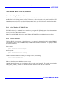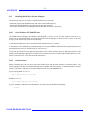
1
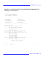
GRMON
GRMON User’s Manual
Version 1.0.13
July 2005
GAISLER RESEARCH AB
-2-
GRMON User’s Manual
Copyright 2004, 2005 Gaisler Research AB.
Permission is granted to make and distribute verbatim copies of this manual provided the copyright
notice and this permission notice are preserved on all copies.
Permission is granted to copy and distribute modified versions of this manual under the conditions
for verbatim copying, provided also that the entire resulting derived work is distributed under the
terms of a permission notice identical to this one.
Permission is granted to copy and distribute translations of this manual into another language, under
the above conditions for modified versions.
GAISLER RESEARCH AB
-3-
GRMON User’s Manual
1
Introduction.................................................................................. 5
1.1
1.2
1.3
1.4
1.5
1.6
2
Overview........................................................................................................
Supported platforms and system requirements ..............................................
Obtaining GRMON........................................................................................
Installation......................................................................................................
GRMON Evaluation version..........................................................................
Problem reports..............................................................................................
5
5
5
5
5
5
Debugging concept ...................................................................... 6
2.1
2.2
2.3
3
Overview........................................................................................................ 6
Target initialization........................................................................................ 7
LEON2 target systems ................................................................................... 9
Operation...................................................................................... 11
3.1
3.2
3.3
3.4
3.4.1
3.4.2
3.4.3
3.4.4
3.4.5
3.4.6
3.4.7
3.4.8
3.4.9
3.5
3.6
3.6.1
3.6.2
3.6.3
3.6.4
3.6.5
3.6.6
4
General...........................................................................................................
Starting GRMON ...........................................................................................
GRMON command-line interface..................................................................
Common debug operations ............................................................................
Loading of files to target memory ..............................................................
Running applications ..................................................................................
Inserting breakpoints and watchpoints........................................................
Displaying processor registers ....................................................................
Displaying memory contents ......................................................................
Using the trace buffer..................................................................................
Profiling ......................................................................................................
Forwarding application console output.......................................................
Multi-processor support ..............................................................................
Symbolic debug information..........................................................................
GDB interface ................................................................................................
Attaching to gdb..........................................................................................
Running application in gdb.........................................................................
Executing GRMON commands in gdb .......................................................
Detaching ....................................................................................................
Specific GDB optimisation .........................................................................
Limitations of gdb interface........................................................................
11
11
12
13
13
13
14
14
14
15
16
17
17
18
19
19
19
20
20
20
20
Debug interfaces .......................................................................... 21
4.1
4.2
4.3
4.4
4.5
Overview........................................................................................................
Serial debug interface ....................................................................................
Ethernet debug interface ................................................................................
PCI debug interface (Linux only) ..................................................................
JTAG debug interface ....................................................................................
21
21
21
22
22
GAISLER RESEARCH AB
-4-
GRMON User’s Manual
5
Debug drivers............................................................................... 23
5.1
LEON2 and LEON3 debug support unit (DSU) drivers................................ 23
5.1.1
Internal commands...................................................................................... 23
5.1.2
Command line switches .............................................................................. 23
5.2
LEON2 memory controller driver ................................................................. 24
5.2.1
Internal commands...................................................................................... 24
5.2.2
Command line switches .............................................................................. 24
5.3
On-chip logic analyser driver (LOGAN)....................................................... 25
5.3.1
Internal commands...................................................................................... 25
6
FLASH programming .................................................................. 28
7
Extending GRMON ..................................................................... 30
7.1
Loadable command module........................................................................... 30
APPENDIX A: GRMON Command description....................................................... 31
APPENDIX B: HASP License key installation ......................................................... 34
GAISLER RESEARCH AB
-5-
GRMON User’s Manual
1
Introduction
1.1 Overview
GRMON is a general debug monitor for the LEON processor, and for SOC designs based on the GRLIB IP
library. GRMON includes the following functions:
•
•
•
•
•
•
Read/write access to all system registers and memory
Built-in disassembler and trace buffer management
Downloading and execution of LEON applications
Breakpoint and watchpoint management
Remote connection to GNU debugger (gdb)
Support for JTAG, RS232, PCI and ethernet debug links
Earlier versions of GRMON included separate back-ends for LEON2 and LEON3 target systems, and also a
LEON2 simulator back-end (TSIM). As of GRMON-1.1 the simulator back-end has been removed and the
LEON2/3 back-ends have been merged. The LEON2 (and LEON3) simulators are available separately.
1.2 Supported platforms and system requirements
GRMON is currently provided for three platforms: Linux-x86, Windows (2K/XP) and Windows with cygwin.
1.3 Obtaining GRMON
The primary site for GRMON is http://www.gaisler.com/, where the latest version of GRMON can be ordered
and evaluation versions downloaded.
1.4 Installation
GRMON can be installed anywhere on the host computer - for convenience the installation directory should be
added to the search path. The commercial versions use a HASP4 license key. See appendix B for installation of
device drivers under Windows and Linux platforms.
1.5 GRMON Evaluation version
The evaluation version of GRMON can be downloaded from www.gaisler.com. The evaluation version may be
used during a period of 21 days without purchasing a license. After this period, any commercial use of
GRMON is not permitted without a valid license. The following features are not available in the evaluation
version:
• Support for LEON-FT
• Loadable modules
• Custom LEON2 configuration files
1.6 Problem reports
Please send problem reports or comments to [email protected].
GAISLER RESEARCH AB
-6-
GRMON User’s Manual
2
Debugging concept
2.1 Overview
The GRMON debug monitor is intended to debug system-on-chip (SOC) designs based on the LEON processor. The monitor connects to a dedicated debug interface on the target hardware, through which it can perform
read and write cycles on the on-chip bus (AHB). The debug interface can be of various types: the LEON2 processor supports debugging over a serial UART and 32-bit PCI, while LEON3 also supports JTAG and ethernet
debug interfaces. On the target system, all debug interfaces are realized as AHB masters with the debug protocol implemented in hardware. There is thus no software support necessary to debug a LEON system, and a target system does in fact not even need to have a processor present.
Terminal
GDB (port 2222)
GRMON
Command layer
Basic commands
IP Debug drivers
GDB protocol
GRLIB Debug Drivers
Debug interface drivers
Serial I/F
PCI
JTAG
Ethernet
PCI
debug link
JTAG
debug link
Ethernet
debug link
Debug interfaces
LEON SOC
TARGET SYSTEM
Serial
debug link
AHB
LEON3
Processor
Memory
Controller
APB
Bridge
Custom
IP core
GRMON can operate in two modes: command-line mode and GDB mode. In command-line mode, GRMON
commands are entered manually through a terminal window. In GDB mode, GRMON acts as a GDB gateway
and translates the GDB extended-remote protocol to debug commands on the target system.
GRMON is implemented using three functional layers: command layer, debug driver layer, and debug interface
layer. The command layer consist of a general command parser which implements commands that are independent of the used debug interface or target system. These commands include program downloading and flash
programming.
GAISLER RESEARCH AB
-7-
GRMON User’s Manual
The debug driver layer implements custom commands which are related to the configuration of the target system. GRMON scans the target system at startup, and detects which IP cores are present and how they are configured. For each supported IP core, a debug driver is enabled which implements additional debug commands
for the specific core. Such commands can consist of memory detection routines for memory controllers, or program debug commands for the LEON processors.
The debug interface layer implements the debug link protocol for each supported debug interface. The protocol
depends on which interface is used, but provides a uniform read/write interface to the upper layers. Which
interface to use for a debug session is specified through command-line options during the start of GRMON.
2.2 Target initialization
When GRMON first connects to the target system, it scans the system to detect which IP cores are present.
This is done by reading the plug&play information which is normally located at address 0xfffff000 on the AHB
bus. A debug driver for each recognized IP core is then initialized, and performs a core-specific initialization
sequence if required. For a memory controller, the initialization sequence would typically consist of a memory
probe operation to detect the amount of attached RAM. For a UART, it could consist of initializing the baud
rate generator and flushing the FIFOs. After the initialization is complete, the system configuration is printed:
GRMON LEON debug monitor v1.1
Copyright (C) 2004,2005 Gaisler Research - all rights reserved.
For latest updates, go to http://www.gaisler.com/
Comments or bug-reports to [email protected]
using port /dev/ttyS0 @ 115200 baud
initialising ..............
detected frequency: 40 MHz
Component
Leon3 SPARC V8 Processor
AHB Debug UART
AHB Debug JTAG TAP
Simple 32-bit PCI Target
AHB interface for 10/100 Mbit MA
LEON2 Memory Controller
AHB/APB Bridge
Leon3 Debug Support Unit
AHB interface for 10/100 Mbit MA
Generic APB UART
Multi-processor Interrupt Ctrl
Modular Timer Unit
Generic APB UART
Vendor
Gaisler Research
Gaisler Research
Gaisler Research
Gaisler Research
Gaisler Research
European Space Agency
Gaisler Research
Gaisler Research
Gaisler Research
Gaisler Research
Gaisler Research
Gaisler Research
Gaisler Research
Use command ’info sys’ to print a detailed report of attached cores
grmon>
GAISLER RESEARCH AB
-8-
GRMON User’s Manual
More detailed system information can be printed using the ‘info sys’ command:
grmon> inf sys
00.01:003
Gaisler Research Leon3 SPARC V8 Processor (ver 0)
ahb master 0
02.01:007
Gaisler Research AHB Debug UART (ver 0)
ahb master 2
apb: 80000700 - 80000800
baud rate 115200, ahb frequency 40.00
03.01:01c
Gaisler Research AHB Debug JTAG TAP (ver 0)
ahb master 3
04.01:012
Gaisler Research Simple 32-bit PCI Target (ver 0)
ahb master 4
05.01:005
Gaisler Research AHB interface for 10/100 Mbit MA (ver 0)
ahb master 5
00.04:00f
European Space Agency LEON2 Memory Controller (ver 0)
ahb: 00000000 - 20000000
ahb: 20000000 - 40000000
ahb: 40000000 - 80000000
apb: 80000000 - 80000100
32-bit prom @ 0x00000000
64-bit sdram: 2 * 128 Mbyte @ 0x40000000, col 9, cas 2, ref 15.6 us
01.01:006
Gaisler Research AHB/APB Bridge (ver 0)
ahb: 80000000 - 80100000
02.01:004
Gaisler Research Leon3 Debug Support Unit (ver 0)
ahb: 90000000 - a0000000
AHB trace 128 lines, stack pointer 0x4ffffff0
CPU#0 win 8, hwbp 2, itrace 128, V8 mul/div, srmmu, lddel 1
icache 2 * 16 kbyte, 32 byte/line lrr
dcache 2 * 16 kbyte, 32 byte/line lrr
05.01:005
Gaisler Research AHB interface for 10/100 Mbit MA (ver 0)
irq 12
ahb: fffb0000 - fffb1000
01.01:00c
Gaisler Research Generic APB UART (ver 1)
irq 2
apb: 80000100 - 80000200
baud rate 38400
02.01:00d
Gaisler Research Multi-processor Interrupt Ctrl (ver 3)
apb: 80000200 - 80000300
03.01:011
Gaisler Research Modular Timer Unit (ver 0)
irq 8
apb: 80000300 - 80000400
8-bit scaler, 2 * 32-bit timers, divisor 40
09.01:00c
Gaisler Research Generic APB UART (ver 1)
irq 3
apb: 80000900 - 80000a00
baud rate 38400
The detailed system view also provides information about address mapping, interrupt allocation and IP core
configuration.
GAISLER RESEARCH AB
-9-
GRMON User’s Manual
2.3 LEON2 target systems
The plug&play information was introduced in the LEON3 processor (GRLIB), and is not available in LEON2.
If GRMON is not able to detect the plug&play area, it will switch to a LEON2 legacy mode. A LEON2 system
has a fixed set of IP cores and address mapping, and GRMON will use an internal plug&play table that
describes this configuration:
GRMON LEON debug monitor v1.1
using port /dev/ttyUSB1 @ 115200 baud
GRLIB plug&play not found, switching to LEON2 legacy mode
initialising .........
detected frequency: 40 MHz
Component
LEON2 Memory Controller
LEON2 SPARC V8 processor
LEON2 Configuration register
LEON2 Timer Unit
LEON2 UART
LEON2 UART
LEON2 Interrupt Ctrl
AHB Debug UART
LEON2 Debug Support Unit
Vendor
European Space Agency
European Space Agency
European Space Agency
European Space Agency
European Space Agency
European Space Agency
European Space Agency
Gaisler Research
Gaisler Research
Use command ’info sys’ to print a detailed report of attached cores
grmon[grlib]> inf sys
00.04:00f
European Space Agency LEON2 Memory Controller (ver 0)
ahb: 00000000 - 20000000
ahb: 20000000 - 40000000
ahb: 40000000 - 80000000
apb: 80000000 - 80000010
8-bit prom @ 0x00000000
32-bit sdram: 1 * 64 Mbyte @ 0x40000000, col 9, cas 2, ref 15.6 us
01.04:002
European Space Agency LEON2 SPARC V8 processor (ver 0)
apb: 80000014 - 80000018
02.04:008
European Space Agency LEON2 Configuration register (ver 0)
apb: 80000024 - 80000028
val: 6877bf00
03.04:006
European Space Agency LEON2 Timer Unit (ver 0)
apb: 80000040 - 80000070
04.04:007
European Space Agency LEON2 UART (ver 0)
apb: 80000070 - 80000080
baud rate 38400
05.04:007
European Space Agency LEON2 UART (ver 0)
apb: 80000080 - 80000090
baud rate 38400
06.04:005
European Space Agency LEON2 Interrupt Ctrl (ver 0)
apb: 80000090 - 800000a0
07.01:007
Gaisler Research AHB Debug UART (ver 0)
apb: 800000c0 - 800000d0
baud rate 115200, ahb frequency 40.00
08.01:002
Gaisler Research LEON2 Debug Support Unit (ver 0)
ahb: 90000000 - a0000000
trace buffer 512 lines, stack pointer 0x43fffff0
CPU#0 win 8, hwbp 2, V8 mul/div, lddel 1
icache 1 * 8 kbyte, 32 byte/line
dcache 1 * 8 kbyte, 32 byte/line
grmon[grlib]>
GAISLER RESEARCH AB
- 10 -
GRMON User’s Manual
The plug&play table used for LEON2 is fixed, and no automatic detection of present cores is attempted. Only
those cores that need to be initialized by GRMON are included in the table, so the listing might not correspond
to the actual target. It is however possible to load a custom configuration file that describes the target system
configuration using the -cfg startup option:
./grmon -cfg leon2.cfg
GRMON LEON debug monitor v1.1
using port /dev/ttyS0 @ 115200 baud
reading configuration from leon2.cfg
initialising ......
detected frequency: 40 MHz
Component
AHB Debug UART
Generic APB UART
LEON2 Interrupt Ctrl
LEON2 Timer Unit
LEON2 Memory Controller
LEON2 Debug Support Unit
Vendor
Gaisler Research
Gaisler Research
European Space Agency
European Space Agency
European Space Agency
Gaisler Research
Use command ’info sys’ to print a detailed report of attached cores
grmon[grlib]> inf sys
00.01:007
Gaisler Research AHB Debug UART (ver 0)
apb: 800000c0 - 800000d0
baud rate 115200, ahb frequency 40.00
01.01:00c
Gaisler Research Generic APB UART (ver 0)
apb: 80000070 - 80000080
baud rate 38400
02.04:005
European Space Agency LEON2 Interrupt Ctrl (ver 0)
apb: 80000090 - 800000a0
03.04:006
European Space Agency LEON2 Timer Unit (ver 0)
apb: 80000040 - 80000070
04.04:00f
European Space Agency LEON2 Memory Controller (ver 0)
ahb: 00000000 - 20000000
ahb: 20000000 - 40000000
ahb: 40000000 - 80000000
apb: 80000000 - 80000010
8-bit prom @ 0x00000000
32-bit sdram: 1 * 64 Mbyte @ 0x40000000, col 9, cas 2, ref 15.6 us
05.01:002
Gaisler Research LEON2 Debug Support Unit (ver 0)
ahb: 90000000 - a0000000
trace buffer 512 lines, stack pointer 0x43fffff0
CPU#0 win 1, lddel 1
icache 4 * 1 kbyte, 4 byte/line lru
dcache 4 * 1 kbyte, 4 byte/line lru
grmon[grlib]>
The format of the plug&play configuration file is described in section x. It can be used for both LEON3 and
LEON2 systems.
GAISLER RESEARCH AB
- 11 -
GRMON User’s Manual
3
Operation
3.1 General
A GRMON debug session typically consists of the following steps:
• Attaching to the target system and examining the configuration
• Uploading application program and executing using GRMON commands
• Attaching to GDB and debugging through the GDB protocol
The following sections will describe how the various steps are performed.
3.2 Starting GRMON
GRMON is started by giving the grmon command in a terminal window. Without options, GRMON will try to
connect to the target using the serial debug link. UART1 of the host (ttyS0 or COM1) will be used, with a
default baud rate of 115200 baud. On windows hosts, GRMON can be started in a command window (command.com) or in a cygwin shell. Below is the syntax and the accepted command line options:
grmon [options]
Options:
-abaud baudrate
Set application baudrate for UART 1 & 2. By default, 38400 baud is used.
-baud brate Use brate for the DSU serial link. By default, 115200 baud is used. Possible baud rates are
9600, 19200, 38400, 57600, 115200, 230400, 460800. Rates above 115200 need special
uart hardware on both host and target.
-c input_file Executable file to be loaded into memory. The input file is loaded into the target memory
according to the entry point for each segment. Recognized formats are elf32 and S-record.
-eth
Connect using ethernet. Requires the EDCL core to be present in the target system.
-freq sysclk Overrides the detected system frequency. The frequency is specified in MHz.
-gdb
Listen for gdb connection directly at start-up.
-jtag
Connect to the JTAG Debug Link using Xilinx Parallel Cable III or IV.
-leon2
Force LEON2 legacy mode.
-pci
Connect to the DSU using PCI device /dev/phob0.
-port gdbport Set the port number for gdb communications. Default is 2222.
-stack val
Set val as stack pointer for applications, overriding the auto-detected value.
-u
Put UART 1 in loop-back mode, and print its output on monitor console.
-uart device By default, GRMON communicates with the target using the first uart port of the host. This
can be overridden by specifying an alternative device. Device names depend on the host
operating system. On unix systems (and cygwin), serial devices are named as /dev/ttyXX.
On windows, use com1 - 4.
-ucmd file
Load a user command module.
In addition, the debug drivers can also accept command line options.
GAISLER RESEARCH AB
- 12 -
GRMON User’s Manual
3.3 GRMON command-line interface
GRMON dynamically loads libreadline.so if available on your host system, and uses readline() to enter and
edit monitor commands. Short forms of the commands are allowed, e.g c, co, or con, are all interpreted as cont.
Tab completion is available for commands, text-symbols and filenames. If libreadline.so is not found, fgets()
is used instead (no history, poor editing capabilities and no tab-completion). Below is a description of some of
the more common commands that are available regardless of loaded debug drivers. For the full list of commands, see appendix A.1.
batch file_name
execute a batch file of grmon commands
disas <addr> [length]
disassemble memory
echo
echo string in monitor window
help
show available commands or usage for specific command
info [drivers | libs | reg | sys] show available debug drivers, system registers or system configuration
loadfile_name
load a file into target memory (elf32 or srecord)
mem[addr] [length]
display memory
symbols
show symbols or load symbols from file
quit
exit grmon
wmem <addr> <data>
write word to memory
Below is a list of some of commands provided by the LEON debug support unit (DSU) debug driver. These
commands are available when a LEON processor and associated debug support unit is present in the target system. See appendix A.2 for a full list of DSU commands.
break <addr>
cont
dcache
delete <bpnum>
float
gdb [port]
go [addr]
hbreak
icache
profile [0 | 1]
register
run [addr]
stack [val]
step [n]
watch [addr]
print or add breakpoint
continue execution
show data cache
delete breakpoint(s)
display FPU registers
connect to gdb debugger
start execution without initialization
print breakpoints or add hardware breakpoint (if available)
show instruction cache
enable/disable/show simple profiling
show/set integer registers
reset and start execution at last entry point, or at addr
show/set the stack pointer
single step one or [n] times
print or add data watchpoint
GAISLER RESEARCH AB
- 13 -
GRMON User’s Manual
3.4 Common debug operations
3.4.1 Loading of files to target memory
A LEON software application can be uploaded to the target system memory using the load command:
grmon> load stanford_leon
section: .text at 0x40000000, size 54368 bytes
section: .data at 0x4000d460, size 2064 bytes
section: .jcr at 0x40024e68, size 4 bytes
total size: 56436 bytes (90.9 kbit/s)
read 196 symbols
entry point: 0x40000000
The supported file format is elf32-sparc and srecord. Each section is loaded to its link address. The program
entry point of the file is use to set the %pc when the application is later started with run. It is also possible to
verify that the file has been loaded correctly using the verify command:
grmon> veri stanford_leon
section: .text at 0x40000000, size 54368 bytes
section: .data at 0x4000d460, size 2064 bytes
section: .jcr at 0x40024e68, size 4 bytes
total size: 56436 bytes (64.9 kbit/s)
entry point: 0x40000000
Any discrepancies will be reported in the GRMON console.
3.4.2 Running applications
To run a program, first use the load command to download the application and the run to start it. The program
should have been compiled with either the BCC, RCC or sparc-linux tool-chain.
grmon> lo stanford_leon
section: .text at 0x40000000, size 54368 bytes
section: .data at 0x4000d460, size 2064 bytes
section: .jcr at 0x40024e68, size 4 bytes
total size: 56436 bytes (90.8 kbit/s)
read 196 symbols
entry point: 0x40000000
grmon> run
Starting
Perm Towers Queens
Intmm
Mm Puzzle
34
67
33
117
1117
367
Nonfloating point composite is
Floating point composite is
Quick
50
Bubble
50
Tree
250
FFT
1133
144
973
Program exited normally.
grmon>
The output from the application normally appears on the LEON UARTs and thus not in the GRMON console.
However, if GRMON is started with the -u switch, the UART output looped back to its own receiver and
printed on the console by GRMON. The application must be reloaded before it can be executed again, in order
to restore the .data segment. If the application uses the LEON MMU (e.g. linux-2.6) or installs data exception
handlers (e.g. eCos), the GRMON should be started with -nb to avoid going into break mode on a page-fault or
data exception. Note that the -u option does not work when for snapgear linux applications. Instead, a terminal
emulator should be connected to UART 1 of the target system.
GAISLER RESEARCH AB
- 14 -
GRMON User’s Manual
3.4.3 Inserting breakpoints and watchpoints
Instruction breakpoints are inserted using the break or hbreak commands. The break command inserts a software breakpoint (ta 1), while hbreak will insert a hardware breakpoint using one of the IU watchpoint registers. To debug code in read-only memories, only hardware breakpoints can be used. Note that it is possible to
debug any RAM-based code using software breakpoints, even where traps are disabled such as in trap handlers.
Data write watchpoints are inserted using the watch command. A watchpoint can only cover one word address,
block watchpoints are not supported by GRMON.
3.4.4 Displaying processor registers
The current register window of a LEON processor can be displayed using the reg command:
grmon> reg
0:
1:
2:
3:
4:
5:
6:
7:
INS
00000008
80000070
0000000D
FFFFFFFF
43FFF7B8
4000D008
43FFF618
00000001
LOCALS
0000000C
00000020
43FFFDF0
00000003
00000001
00000004
00000000
00000010
OUTS
00000008
80000070
0000000D
FFFFFFFF
43FFF7B8
4000D008
43FFF618
00000001
psr: F20000E2
wim: 00000080
pc: 40003e44
npc: 40003e48
be 0x40003fb8
mov %i1, %i3
GLOBALS
00000000
00000008
43FFF6F8
4000D010
00000001
00000000
00000000
4000633C
tbr: 40000060
y: 00000000
Other register windows can be displayed using reg wn, when n denotes the window number. Use the float
command to show the FPU registers (if present).
3.4.5 Displaying memory contents
Any memory location can be displayed using the mem (or x) command. The command requires an address and
an optional length. If a length argument is provided, that is interpreted as the number of bytes to display. If a
program has been loaded, text symbols can be used instead of a numeric address. The memory content is displayed hexa-decimal format, grouped in 32-bit words. The ASCII equivalent is printed at the end of the line.
grmon> mem 0x40000000
40000000
40000010
40000020
40000030
a0100000
91d02000
91d02000
91d02000
29100004
01000000
01000000
01000000
81c52000
01000000
01000000
01000000
01000000
01000000
01000000
01000000
...)....Å .....
. .............
. .............
. .............
29100004
81c52000
01000000
...)....Å .....
2f100085
d025e178
11100033
31100037
11100033
40000af4
90100000
40000b4b
901223c0
.ã¿./...1..7....
& À%á[email protected]
..#˚...3@..ô..#À
grmon> mem 0x40000000 16
40000000
a0100000
grmon> mem main 48
40003278
40003288
40003298
9de3bf98
d02620c0
901223b0
GAISLER RESEARCH AB
- 15 -
GRMON User’s Manual
If the memory contents is SPARC machine code, the contents can be displayed in assembly code using the
disas command:
grmon> dis
40000000
40000004
40000008
4000000c
40000010
40000014
40000018
4000001c
40000020
40000024
0x40000000
a0100000
29100004
81c52000
01000000
91d02000
01000000
01000000
01000000
91d02000
01000000
10
clr %l0
sethi %hi(0x40001000), %l4
jmp %l4
nop
ta 0x0
nop
nop
nop
ta 0x0
nop
grmon> dis
40003278
4000327c
40003280
40003284
40003288
4000328c
40003290
40003294
40003298
4000329c
400032a0
400032a4
main
9de3bf98
2f100085
31100037
90100000
d02620c0
d025e178
11100033
40000b4b
901223b0
11100033
40000af4
901223c0
save %sp, -104, %sp
sethi %hi(0x40021400),
sethi %hi(0x4000dc00),
clr %o0
st %o0, [%i0 + 0xc0]
st %o0, [%l7 + 0x178]
sethi %hi(0x4000cc00),
call 0x40005fc0
or %o0, 0x3b0, %o0
sethi %hi(0x4000cc00),
call 0x40005e70
or %o0, 0x3c0, %o0
%l7
%i0
%o0
%o0
3.4.6 Using the trace buffer
The LEON processor and associated debug support unit (DSU) can been configured with trace buffers to store
both the latest executed instructions and the latest AHB bus transfers. The trace buffers are automatically
enabled by GRMON during startup, but can also be individually enabled and disabled using tmode command.
The commands ahb, inst and hist commands are used to display the contents of the buffers. Below is an example debug session that shows the usage of breakpoints, watchpoints and the trace buffer:
grmon> load samples/stanford
section: .text at 0x40000000, size 41168 bytes
section: .data at 0x4000a0d0, size 1904 bytes
total size: 43072 bytes (94.2 kbit/s)
read 158 symbols
grmon> tm both
combined processor/AHB tracing
grmon> break Fft
grmon> watch 0x4000a500
grmon> bre
num
address
type
1 : 0x40003608
(soft)
2 : 0x4000a500
(watch)
grmon> run
watchpoint 2 free + 0x1c8 (0x400042d0)
grmon> ahh
time
address
type
data
trans size burst mst lock resp
239371467 400042d8 read
38800002
3
2
1
0
0
0
239371469 400042dc read
d222a100
3
2
1
0
0
0
239371472 4000a4fc read
00000000
2
2
0
0
0
0
239371480 4000a4fc write 000005d0
2
2
0
0
0
0
239371481 90000000 read
000055f9
2
2
0
3
0
0
GAISLER RESEARCH AB
tt
06
06
06
06
06
pil irl
0
0
0
0
0
0
0
0
0
0
- 16 -
GRMON User’s Manual
grmon> inst
time
address
instruction
239371473 400042bc ld [%o2 + 0xfc], %o0
239371475 400042c0 cmp %o1, %o0
239371476 400042c4 bgu,a 0x400042cc
239371478 400042c8 st %o1, [%o2 + 0xfc]
239371479 400042cc sethi %hi(0x4000a400), %o2
grmon> del 2
grmon> break
num
address
type
1 : 0x40003608
(soft)
grmon> cont
breakpoint 1 Fft (0x40003608)
grmon> hist
254992755 40003870 sethi %hi(0x4001f800), %l0
254992759
ahb read, mst=0, size=2
254992760 40003874 mov 19, %i0
254992761
ahb read, mst=0, size=2
254992762 40003878 mov 256, %o0
254992763
ahb read, mst=0, size=2
254992764 4000387c or %l2, 0x28c, %o1
254992765
ahb read, mst=0, size=2
254992766 40003880 or %l1, 0x198, %o2
254992767
ahb read, mst=0, size=2
254992769
ahb read, mst=0, size=2
254992771 40003884 or %l0, 0x3cc, %o3
254992772 40003888 sethi %hi(0x3fb00000), %o4
254992773 4000388c call 0x40003608
254992774 40003890 mov 0, %o5
result
[00000000]
[000005d0]
[00000000]
[4000a4fc 000005d0]
[4000a400]
[4001f800]
[40003880 94146198]
[00000013]
[40003884 961423cc]
[00000100]
[40003888 190fec00]
[40014e8c]
[4000388c 7fffff5f]
[40014598]
[40003890 9a102000]
[40003894 b0863fff]
[4001fbcc]
[3fb00000]
[4000388c]
[00000000]
When printing executed instructions, the value within brackets denotes the instruction result, or in the case of
store instructions the store address and store data. The value in the first column displays the relative time, equal
to the DSU timer. The time is taken when the instruction completes in the last pipeline stage (write-back) of the
processor. In a mixed instruction/AHB display, AHB address and read or write value appear within brackets.
The time indicates when the transfer completed, i.e. when HREADY was asserted. Note: when switching
between tracing modes the contents of the trace buffer will not be valid until execution has been resumed and
the buffer refilled.
3.4.7 Profiling
GRMON supports profiling of LEON applications when run on real hardware. The profiling function collects
(statistical) information on the amount of execution time spend in each function. Due to its non-intrusive
nature, the profiling data does not take into consideration if the current function is called from within another
procedure. Even so, it still provides useful information and can be used for application tuning.
grmon> profile 1
Profiling enabled
grmon> run
resuming at 0x40000000
Starting
Perm Towers Queens
50
33
17
Intmm
116
Mm
1100
Nonfloating point composite is
Floating point composite is
Puzzle
217
Quick
33
Bubble
34
Tree
266
FFT
934
126
862
Program exited normally.
GAISLER RESEARCH AB
- 17 -
GRMON User’s Manual
grmon> prof
function
__unpack_f
__mulsf3
__pack_f
__divdi3
.umul
Fit
__muldi3
_window_overflow
Insert
__addsf3
_window_underflow
__subsf3
Fft
start
Innerproduct
Bubble
rInnerproduct
Place
Remove
Try
Permute
samples
23627
22673
17051
14162
8912
7594
6453
3779
3392
3327
2734
2409
2207
2165
2014
1767
1443
1371
1335
1275
1125
ratio(%)
16.92
16.24
12.21
10.14
6.38
5.44
4.62
2.70
2.42
2.38
1.95
1.72
1.58
1.55
1.44
1.26
1.03
0.98
0.95
0.91
0.80
NOTE: profiling is not available on early LEON2-FT processors, such as LEON2FT-UMC and AT697.
3.4.8 Forwarding application console output
If GRMON is started with -u, the LEON UART1 will be placed in loop-back mode, with flow-control enabled.
During the execution of an application, the UART receiver will be regularly polled, and all application console
output will be printed on the GRMON console. It is then not necessary to connect a separate terminal to
UART1 to see the application output. For this to work, the following restrictions must be met by the application:
• The UART control register must not be modified such that loop-back is disabled
• The UART data register must not be read
3.4.9 Multi-processor support
In systems with more than one LEON3 processors, the cpu command can be used to control the state and
debugging focus of the processors. In MP systems, the processors are enumerated with 0 - n-1, where n is the
number of processors. Each processor can be in two states; enabled or disabled. When enabled, the processor
will be started when any of the run, cont or go commands are given. When disabled, the processor will remain
halted regardless of which command that are given. In addition, one of the enabled processor will also be
active. All debugging commands such as displaying registers or adding break points will be directed to the
active processor only. Switching of active processor can be done using the ‘cpu active n’ command
At start-up, processor 0 is enabled and active while remaining processors are disabled. This allows non-MP
software to execute on MP systems. Additional processors can be enabled using the ‘cpu enable n’ command:
GAISLER RESEARCH AB
- 18 -
GRMON User’s Manual
grmon[grlib]> cpu
cpu 0: enabled active
cpu 1: disabled
grmon[grlib]> cpu en 1
cpu 0: enabled active
cpu 1: enabled
grmon[grlib]> cpu act 1
cpu 0: enabled
cpu 1: enabled active
If grmon is started with the -mp switch, all processors will be enabled by default.
Breakpoints are maintained on processor basis. When executing, only the breakpoints of the active processor
are enabled, the breakpoints of the other processors are not enabled or inserted into the main memory.
It is possible to debug MP systems using gdb. When gdb is attached, it is the currently active processor that will
receive the gdb commands. Switching of processor can only be done by detaching gdb, selecting a different
processor to become active, and the re-attaching gdb. Note that gdb remembers the breakpoints between detach
and re-attachment.
3.5 Symbolic debug information
GRMON will automatically extract (.text) symbol information from elf-files. The symbols can be used where
an address is expected:
grmon> break main
grmon> run
breakpoint 1 main (0x40001ac8)
grmon> disas strlen 3
40001e4c 808a2003
andcc %o0, 0x3, %g0
40001e50 12800016
bne 0x40001ea8
40001e54 96100008
mov %o0, %o3
The symbols command can be used to display all symbols, or to read in symbols from an alternate (elf) file:
grmon[dsu]> symbols samples/hello
read 71 symbols
grmon[dsu]> symbols
0x40000000 L _trap_table
0x40000000 L start
0x4000102c L _window_overflow
0x40001084 L _window_underflow
0x400010dc L _fpdis
0x400011a4 T _flush_windows
0x400011a4 T _start
0x40001218 L fstat
...
Reading symbols from alternate files is necessary when debugging self-extracting applications, such as bootproms created with mkprom or linux/uClinux.
GAISLER RESEARCH AB
- 19 -
GRMON User’s Manual
3.6 GDB interface
3.6.1 Attaching to gdb
GRMON can act as a remote target for gdb, allowing symbolic debugging of target applications. To initiate gdb
communications, start the monitor with the -gdb switch or use the GRMON gdb command:
$ grmon -gdb
using port /dev/ttyS0 @ 115200 baud
gdb interface: using port 2222
Then, start gdb in a different window and connect to GRMON using the extended-remote protocol. By default,
GRMON listens on port 2222 for the gdb connection:
(gdb) target extended-remote pluto:2222
Remote debugging using pluto:2222
0x40000800 in start ()
(gdb)
3.6.2 Running application in gdb
To load and start an application, use the gdb load and run command.
$ gdb stanford
(gdb) target extended-remote pluto:2222
Remote debugging using pluto:2222
0x40000800 in start ()
(gdb) load
Loading section .text, size 0xcb90 lma 0x40000000
Loading section .data, size 0x770 lma 0x4000cb90
Start address 0x40000000, load size 54016
Transfer rate: 61732 bits/sec, 278 bytes/write.
(gdb) bre main
Breakpoint 1 at 0x400039c4: file stanford.c, line 1033.
(gdb) run
The program being debugged has been started already.
Start it from the beginning? (y or n) y
Starting program: /home/john/samples/stanford
Breakpoint 1, main () at stanford.c:1033
1033
fixed = 0.0;
(gdb)
To interrupt execution, Ctrl-C can be typed in both GDB and GRMON windows. The program can be restarted
using the GDB run command but a load has first to be executed to reload the program image on the target.
Software trap 1 (ta 1) is used by gdb to insert breakpoints and should not be used by the application.
GAISLER RESEARCH AB
- 20 -
GRMON User’s Manual
3.6.3 Executing GRMON commands in gdb
While gdb is attached to GRMON, normal GRMON commands can be executed using the gdb monitor command. Output from the GRMON commands is then displayed in the gdb console:
(gdb) monitor hist
time
address
4484188 40001e90
4484194 40001e94
4484195 40001e98
4484196 40001e9c
4484197 40001ea0
4484198 40001e8c
4484200 40001e90
4484201 40001e94
4484202 40001e98
4484203 40001e9c
instruction
add %g2, %o2, %g3
andn %g3, %g2, %g2
andcc %g2, %o0, %g0
be,a 0x40001e8c
add %o1, 4, %o1
ld [%o1], %g2
add %g2, %o2, %g3
andn %g3, %g2, %g2
andcc %g2, %o0, %g0
be,a 0x40001e8c
result
[6e1f766e]
[001f0000]
[00000000]
[40001e3c]
[40003818]
[726c6421]
[716b6320]
[01030300]
[00000000]
[40001e3c]
3.6.4 Detaching
If gdb is detached using the detach command, the monitor returns to the command prompt, and the program
can be debugged using the standard GRMON commands. The monitor can also be re-attached to gdb by issuing the gdb command to the monitor (and the target command to gdb).
GRMON translates SPARC traps into (unix) signals which are properly communicated to gdb. If the application encounters a fatal trap, execution will be stopped exactly before the failing instruction. The target memory
and register values can then be examined in gdb to determine the error cause.
3.6.5 Specific GDB optimisation
GRMON detects gdb access to register window frames in memory which are not yet flushed and only reside in
the processor register file. When such a memory location is read, GRMON will read the correct value from the
register file instead of the memory. This allows gdb to form a function trace-back without any (intrusive) modification of memory. This feature is disabled during debugging of code where traps are disabled, since not valid
stack frame exist at that point.
GRMON detects the insertion of gdb breakpoints, in form of the ‘ta 1’ instruction. When a breakpoint is
inserted, the corresponding instruction cache tag is examined, and if the memory location was cached the tag is
cleared to keep memory and cache synchronized.
3.6.6 Limitations of gdb interface
For optimal operation, gdb-5.3 configured for grmon should be used (provided with RCC and BCC compilers).
Do not use the gdb where command in parts of an application where traps are disabled (e.g.trap handlers).
Since the stack pointer is not valid at this point, gdb might go into an infinite loop trying to unwind false stack
frames.
GAISLER RESEARCH AB
- 21 -
GRMON User’s Manual
4
Debug interfaces
4.1 Overview
The default communications interface between GRMON and the target system is the host’s serial port, connect
to the AHB uart of the target system. Connecting using JTAG, PCI or ethernet can be performed using the
switches listed below:
-eth
-pci
-jtag
Connect using ethernet. Requires the EDCL core to be present in the target system.
Connect to the DSU using PCI device /dev/phob0.
Connect to the JTAG Debug Link using Xilinx Parallel Cable III or IV.
4.2 Serial debug interface
To successfully attach GRMON using the AHB uart, first connect the serial cable between the uart connectors
on target board and the host system. Then power-up and reset the target board and start GRMON. Use the -uart
option in case the target is not connected to the first uart port of your host. Below is a list of start-up switches
applicable for the AHB uart interface:
-baud baudrate
Use baudrate for the DSU serial link. By default, 115200 baud is used. Possible baud
rates are 9600, 19200, 38400, 57600, 115200, 230400, 460800. Rates above 115200
need special uart hardware on both host and target.
-ibaud baudrate Use baudrate to determine the target processor frequency. Lower rate means higher
accuracy. The detected frequency is printed on the console during startup. By default,
115200 baud is used.
-uart device
By default, GRMON communicates with the target using the first uart port of the host.
This can be overridden by specifying an alternative device. Device names depend on
the host operating system. On unix systems (and cygwin), serial devices are named as
/dev/ttyXX. On windows, use com1 - 4.
When GRMON connects to the target with the serial interface, the system clock frequency is calculated by
comparing the setting in the AHB uart baud rate generator to the used communications baud rate. This detection has limited accuracy, but can be improved by selecting a lower detection baud rate using the -ibaud
switch. On some hosts, it might be necessary to lower the baud rate in order to achieve a stable connection to
the target. In this case, use the -baud switch with the 57600 or 38400 options.
4.3 Ethernet debug interface
If the target system uses the EDCL ethernet communication link core, GRMON can connect to the system
using ethernet. In this case, start GRMON with -eth. The default network parameters can be set through additional switches:
-emem <size>
Use size for the target system’s EDCL packet buffer. Default is 2 (kbytes)
-ip <ipnum>
Use ipnum for the target system IP number. Default is 192.168.0.51.
-udp <port>
Use port for the target systemUDP port. Default is 8000.
It is important not to specify more memory with the -emem switch than what is implemented in the EDCL
core.
GAISLER RESEARCH AB
- 22 -
GRMON User’s Manual
4.4 PCI debug interface (Linux only)
If target system has a PCI interface, GRMON can connect to the system using the PCI bus. In this case, start
GRMON with -pci or -pcidev # (see options below). The PCI interfaces uses the open-source PHOB generic
device driver for linux, which must loaded before GRMON is started:
root@mars:~/phob-1.0# ./phob_load vendor_id=0x16e3 device_id=0x021
When the PHOB driver is loaded, make sure that the corresponding devices are writable by the user. The driver
includes a script (phob_load) that can be edited for the correct chmod operation. Once the driver is loaded, start
GRMON with the -pci switch.
-uart device
The -uart is also used when more than one board is handled by the phob driver, e.g.:
grmon -i -pci -uart /dev/phob0afor 1st board
grmon -i -pci -uart /dev/phob1afor 2nd board
GRMON supports the Gaisler Research PCI cores inside GRLIB (pci_gr, pci_target, pci_mtf, pcidma) and the
Insilicon PCI core (pci_is) on the AT697 (LEON2-FT) device.
4.5 JTAG debug interface
If target system has the JTAG AHB debug interface, GRMON can connect to the system through Xilinx Parallel Cable III or IV. The cable should be connected to the host computers parallel port, and GRMON should be
started with the -jtag switch. On linux systems, the GRMON binary has to be owned by the superuser (root)
and have ‘s’ (set user or group ID on execution) permission bit set (chmod +s grmon). GRMON will report the
devices in the JTAG chain. If an unknown device is found, initialization of the JTAG chain will fail and
GRMON will report the JTAG ID of the unknown device. In this case, report the device ID and corresponding
JTAG instruction register length to Gaisler Research and the device will be supported in a future release of
GRMON.
$ grmon -jtag -u
using JTAG cable on parallel port
JTAG chain: xc3s1500 xcf04s xcf04s
.
.
GAISLER RESEARCH AB
- 23 -
GRMON User’s Manual
5
Debug drivers
5.1 LEON2 and LEON3 debug support unit (DSU) drivers
The DSU debug drivers for LEON2 and LEON3 processors handle most of the functions regarding application
debugging, processor register access and trace buffer handling. Since the DSU for LEON2 and LEON3 are not
identical, two separate drivers are used.
5.1.1 Internal commands
The driver for the LEON2/3 debug support unit provides the following internal commands:
ahb [length]
Print the AHB trace buffer. The length AHB transfers will be printed, default is 10.
break <addr>
print or add breakpoint
cont
continue execution
cpu [enable | disable | active] cpuid
Control processors in LEON3 multi-processor (MP) systems. Without parameters, the
cpu command prints the processor status.
dcache[0 | 1]
show, enable or disable data cache
delete <bpnum> delete breakpoint(s)
float
display FPU registers
gdb [port]
connect to gdb debugger
go [addr]
start execution without initialization
hbreak
print breakpoints or add hardware breakpoint (if available)
hist [length]
Print the trace buffer. The length last executed instructions or AHB transfers will be
printed, default is 10.
icache [0 | 1]
show, enable or disable instruction cache
profile [0 | 1]
enable/disable/show simple profiling
register
show/set integer registers
run [addr]
reset and start execution at last entry point, or at addr
stack [val]
show/set the stack pointer
step [n]
single step one or [n] times
tmode [proc | ahb | both | none]
Select tracing mode between none, processor-only, AHB only or both.
wash
Clear all SRAM and SDRAM memory
watch [addr]
print or add data watchpoint
5.1.2 Command line switches
The following command line switches are accepted:
-mp
Start-up in MP mode (all processors enabled)
GAISLER RESEARCH AB
- 24 -
GRMON User’s Manual
5.2 LEON2 memory controller driver
The LEON2 memory controller debug driver provides functions for memory probing and waitstate control.
5.2.1 Internal commands
mcfg1 [value] Set the default value for memory configuration register 1. When the ‘run’ command is
given, MCFG1, 2&3 are initialized with their default values to provide the application
with a clean startup environment. If no value is give, the current default value is
printed.
mcfg2 [value] As mcfg1 above, but setting the default value of the MCFG2 register.
mcfg3 [value] As mcfg1 above, but setting the default value of the MCFG3 register.
5.2.2 Command line switches
The following start-up switches are recognized:
-banks ram_banks
-cas delay
-nosram
-ram ram_size
Overrides the auto-probed number of populated ram banks.
Programs SDRAM to either 2 or 3 cycles CAS delay. Default is 2.
Disable sram and map sdram from address 0x40000000
Overrides the auto-probed amount of static ram. Size is given in Kbytes.
-romrws waitstates
Set waitstates number of waitstates for rom reads.
-romwws waitstates
Set waitstates number of waitstates for rom writes.
-romws waitstates
Set waitstates number of waitstates for both rom reads and writes.
-ramrws waitstates
Set waitstates number of waitstates for ram reads.
-ramwws waitstates
Set waitstates number of waitstates for ram writes.
-ramws waitstates
Set waitstates number of waitstates for both ram reads and writes.
GAISLER RESEARCH AB
- 25 -
GRMON User’s Manual
5.3 On-chip logic analyser driver (LOGAN)
The LOGAN debug driver contains commands to control the LOGAN on-chip logic analyzer core. It allows to
set various triggering conditions, and to generate VCD waveform files from trace buffer data. All logic analyzer commands are prefixed with la.
5.3.1 Internal commands
la status
Reports status of logan (equivalent with writing just la).
la arm
Arms the logan. Begins the operation of the analyzer and sampling starts.
la reset
Stop the operation of the logan. Logic Analyzer returns to idle state.
la pm [trig level] [pattern] [mask]
Sets/displays the complete pattern and mask of the specified trig level. If not fully
specified the input is zero-padded from the left. Decimal notation only possible for
widths less than or equal to 64 bits.
la pat [trig level] [bit] [0 | 1]
Sets/displays the specified bit in the pattern of the specified trig level to 0/1.
la mask [trig level] [bit] [0 | 1]
Sets/displays the specified bit in the mask of the specified trig level to 0/1.
la trigctrl [trig level] [match counter] [trig condition]
Sets/displays the match counter and the trigger condition (1 = trig on equal, 0 = trig on
not equal) for the specified trig level.
la count [value]
Set/displays the trigger counter. The value should be between zero and depth-1 and
specifies how many samples that should be taken after the triggering event.
la div [value]
Sets/displays the sample frequency divider register. If you specify e.g. “la div 5” the
logic analyzer will only sample a value every 5th clock cycle.
la qual [bit] [value]Sets/displays which bit in the sampled pattern that will be used as qualifier and what
value it shall have for a sample to be stored.
la dump [filename] This dumps the trace buffer in VCD format to the file specified (default is log.vcd).
la view [start index] [stop index] [filename]
Prints the specified range of the trace buffer in list format. If no filename is specified
the commands prints to the screen.
la page [page]
Sets/prints the page register of the logan. Normally the user doesn’t have to be concerned with this because dump and view sets the page automatically. Only useful if
accessing the trace buffer manually via the grmon mem command
The LOGAN driver can create a VCD waveform file using the ‘la dump’ command. The file setup.logan is
used to define which part of the trace buffer belong to which signal. The file is read by the debug driver before
a VCD file is generated. An entry in the file consists of a signal name followed by its size in bits separated by
white-space. Rows not having these two entries as well as rows beginning with an # are ignored.
GAISLER RESEARCH AB
- 26 -
GRMON User’s Manual
Example:
count31_16 16
count15_6 10
count5_0 6
This configuration has a total of 32 traced signals and they will be displayed as three different signals being 16,
10 and 6 bits wide. The first signal in the configuration file maps to the most significant bits of the vector with
the traced signals. The created VCD file can be opened by waveform viewers such as GTKWave or Dinotrace.
Below is an example trace displayed in GTKWave.
To simplify the operation of the logic analyzer, a graphical GUI is available. The GUI is written in Tcl/Tk and
can be connected to GRMON using the gdb interface. To use the GUI, enter the gdb command in GRMON and
then launch the tcl file logan.tcl.
The left side of the GUI window has the settings for the different trig levels, i.e. pattern, mask, match counter
and trigger condition. Which trig level the settings apply to is chosen from an option menu. The “Download
conf” button transfers the values to the on-chip logic analyzer. The pattern and mask is padded with zeroes
from the left if not fully specified. They can be entered either in hexadecimal or decimal but there is a limitation that no signal can be wider than 64 bits.
The right side of the window shows the status the settings which control the trace buffer. These settings are sent
to the logic analyzer when the user presses enter. The ‘armed’ and ‘triggered’ fields of the status can be re-read
by pressing the “Update status” button.
There are also buttons to arm and reset the logic analyzer as well as to dump the vcd-file and launch GTKWave. Any GRMON command can be issued from the entry below these buttons.
From the file menu the current configuration can be saved and a new one can be loaded. The GUI defaults to
the same configuration file as the GRMON debug driver. If the configuration is saved it adds information about
the setup which is ignored by GRMON. When saving/loading any filename may be specified but during startup
the GUI reads the “setup.logan” file. Only files previously saved by the GUI can be loaded from this menu
option.
GAISLER RESEARCH AB
- 27 -
GRMON User’s Manual
GAISLER RESEARCH AB
- 28 -
GRMON User’s Manual
6
FLASH programming
GRMON includes flash programming routines intended to used with Gaisler Research’s and Pender Electronic
Design’s LEON2/3 development boards. Other boards might be supported if they use Intel flash proms, but no
guarantees are given. The flash programming commands are only supported if the target system contains a
LEON2 memory controller (MCTRL). Both 32- and 8-bit wide proms are supported, but not 16-bit. It is imperative that the prom width in the MCFG1 register correctly reflects the width of the external prom. The following flash programming commands are provided:
flash
Print the on-board flash memory configuration
flash disable
Disable writing to flash
flash erase [addr | all]
Erase a flash block at address addr, or the complete flash memory (all). An address
range is also support,e.g. ‘flash erase 0x1000 0x8000’.
flash load <file>
Program the flash memory with the contents file. Recognized file formats are ELF and
srecord.
flash lock [addr | all]
Lock a flash block at address addr, or the complete flash memory (all). An address
range is also support, e.g. ‘flash lock 0x1000 0x8000’.
flash lockdown [addr | all]
Lock-down a flash block at address addr, or the complete flash memory (all). An
address range is also support, e.g. ‘flash lockdown 0x1000 0x8000’.
flash query
Print the flash query registers
flash status
Print the flash lock status register
flash unlock [addr | all]
Unlock a flash block at address addr, or the complete flash memory (all). An address
range is also support, e.g. ‘flash unlock 0x1000 0x8000’.
flash write <addr> <data>
Write a 32-bit data word to the flash at address addr.
A typical command sequence to erase and re-program a flash memory could be:
flash
flash
flash
flash
flash
enable
unlock all
erase all
load file.exe
lock all
GAISLER RESEARCH AB
- 29 -
GRMON User’s Manual
GAISLER RESEARCH AB
- 30 -
GRMON User’s Manual
7
Extending GRMON
7.1 Loadable command module
It is possible for the user to add custom commands to GRMON by creating a loadable command module. The
module should export a pointer of type UserCmd_T, called UserCommands, e.g.:
UserCmd_T *UserCommands = &CommandExtension;
UserCmd_T is defined as:
typedef struct
{
/* Functions exported by grmon */
int (*MemoryRead )(unsigned int
int (*MemoryWrite )(unsigned int
void (*GetRegisters)(unsigned int
void (*SetRegisters)(unsigned int
void (*dprint)(char *string);
addr, unsigned char *data, unsigned int length);
addr, unsigned char *data, unsigned int length);
registers[]);
registers[]);
/* Functions provided by user */
int (*Init)();
int (*Exit)();
int (*CommandParser)(int argc, char *argv[]);
char **Commands;
int
NumCommands;
} UserCmd_T;
The first five entries is function pointers that are provided by GRMON when loading the module
• MemoryRead implements an AHB read on the target system. The AHB address is passed in addr, while
the read data is returned in the *data pointer. The length parameter defines the number of bytes to read.
• MemoryWrite implements an AHB write on the target system. The AHB address is passed in addr,
while *data should point to the data to be written. The length parameter defines the number of bytes
to be written. The write length should be a multiple of 4.
• GetRegisters gets the processor registers. See thet grmon.h include file for register definitions.
• SetRegisters sets the processor registers. See thet grmon.h include file for register definitions.
• dprint prints a string to the GRMON console
.
The five last entries are to be implemented by the user:
• Init and Exit are called when entering and leaving a grmon target.
• CommandParser are called from GRMON before any internal parsing is done. This means that you
can override internal GRMON commands. On success CommandParser should return 0 and on error
the return value should be > 200. On error, GRMON will print out the error number for diagnostics.
argv[0] is the command itself and argc is the number of tokens, including the command, that is
supplied.
• Commands should be a list of available commands. (used for command completion)
• NumCommands should be the number of entries in Commands. It is crucial that this number matches
the number of entries in Commands. If NumCommands is set to 0(zero), no command completion will
be done.
A simple example of a command module is supplied with the professional version of grmon.
GAISLER RESEARCH AB
- 31 -
APPENDIX
APPENDIX A: GRMON Command description
A.1
GRMON built-in commands
Command
Description
batch [-echo] <batchfile>
Execute a batch file of grmon commands from <batchfile>. Echo commands if -echo
is specified.
baud <rate>
Change DSU baud rate.
disassemble [addr [cnt]]
Disassemble [cnt] instructions at [addr].
echo
Echo string in monitor window.
exit
Alias for ‘quit’, exits monitor.
help [cmd]
Show available commands or usage for specific command.
info [drv | libs | reg | sys]
Show debug drivers, libraries, system regsiter or system configuration
load <file>
Load a file into memory. The file should be in ELF32, srecords or a.out format.
mem [addr] [count]
Examine memory at at [addr] for [count] bytes.
shell <command>
Execute a shell command.
symbols [symbol_file]
Show symbols or load symbols from file.
quit
Exit grmon and return to invoker(the shell).
verify <file>
Verify memory contents against file.
version
Show version.
wmem <addr> <data>
Write <data> to memory at address <addr>.
Table 1: GRMON built-in commands
GAISLER RESEARCH AB
- 32 -
A.2
APPENDIX
LEON2/3 DSU commands
Command
Description
ahb [trace_length]
Show AHB trace.
break [addr]
Print breakpoints or add breakpoint if addr is supplied. Text symbols can be used
instead of an address.
bt
Print backtrace.
cont
Continue execution.
cp
Show registers in co-processor (if present).
dcache
Show data cache.
delete <bp>
Delete breakpoint ‘bp’.
float
Display FPU registers.
gdb [port]
Connect to the GNU debugger (gdb).
go
Start execution at <addr> without initialisation.
hbreak [addr]
Print breakpoints or add hardware breakpoint.
hist [trace_length]
Show trace history.
icache
Show instruction cache
inst [trace_length]
Show traced instructions.
leon
Show LEON registers.
mmu
Print mmu registers.
profile [0|1]
enable/disable simple profiling. No arguments shows current profiling statistics.
register [reg|win] [val]
Show/set integer registers (or windows, eg ’re w2’)
run
Run loaded application.
stack <addr>
Set stack pointer for next run.
step [n]
Single step one or [n] times.
tm [ahb | proc | both | none]
Select trace mode.
tra [inst_count]
Trace [inst_count] instructions.
va <addr>
Performs a virtual-to-physical translation of address.
version
Show version.
watch [addr]
Print or add watchpoint.
Table 2: LEON2/3 DSU commands
GAISLER RESEARCH
- 33 -
APPENDIX
A.3
FLASH programming commands
Command
Description
flash
Print the detected flash memory configuration.
flash disable
Disable writes to flash memory.
flash enable
Enable writes to flash memory.
flash erase [addr]|all
Erase flash memory blocks.
flash load <file>
Program file into flash memory
flash lock [addr]|all
Lock flash memory blocks.
flash lockdown [addr]|all
Lockdown flash memory blocks.
flash query
Print the flash memory query register contents.
flash status
Print the flash memory block lock status.
flash unlock [addr]|all
Unlock flash memory blocks.
flash write [addr] [data]
Write single data value to flash address.
Table 3: FLASH programming commands
GAISLER RESEARCH AB
- 34 -
APPENDIX
APPENDIX B: HASP License key installation
B.1
Installing HASP Device Driver
Two versions of the HASP USB hardware key are available, HASP4 M1 for node-locked licenses (blue key),
and HASP4 Net for floating licenses (red key). Before use, a device driver for the key must be installed. The
latest drivers can be found at www.ealaddin.com or www.gaisler.com. If a floating-license key is used, the
HASP4 network license server also has to be installed and started. The necessary server installation documentation can be obtained from the distribution CD or from www.ealaddin.com.
B.1.1
On a Windows NT/2000/XP host
The HASP device driver is installed automatically when using the HASPUserSetup.exe located in hasp/windows/driver directory the GRMON CD. It automatically recognize the operating system in use and install the
correct driver files at the required location.
Note: To install the HASP device driver under Windows NT/2000/XP, you need administrator privileges.
B.1.2
On a Linux host
The linux HASP driver consists of aksusbd daemon. It is contained in the hasp/linux/driver on the GRMON
CD. The driver comes in form of RPM packages for Redhat and Suse linux distributions. The packages should
be installed as follows:
Suse systems:
rpm -i aksusbd-suse-1.8.1-2.i386.rpm
Redhat systems:
rpm -i aksusbd-redhat-1.8.1-2.i386.rpm
The driver daemon can then be started by re-booting the most, or executing:
/etc/rc.d/init.d/aksusbd start
Note: All described action should be executed as root.
On other linux distributions, the driver daemon will have to be started manually. This can be done using the
HDD_Linux_dinst.tar.gz, which also contains instruction on how to install and start the daemon.
GAISLER RESEARCH
APPENDIX
B.2
- 35 -
Installing HASP4Net License Manager
The following steps are necessary to install HASP4 Net in a network:
• Install the appropriate HASP daemon and connect the HASP4 Net key.
• Install and start the HASP License Manager on the same machine.
• Customize the HASP License Manager and the HASP4 Net client, if necessary.
B.2.1
On a Windows NT/2000/XP host
The HASP License Manager for Windows NT/2000/XP is nhsrvice32.exe. Use the setup file lmsetup.exe to
install it. It is recommended that you install the HASP License Manager as an NT service, so there is no need
to log in to the station to provide the functionality.
1. Install the HASP device driver and connect the HASP4 Net key to a station.
2. Install the License Manager by running lmsetup.exe from the GRMON CD and following the instructions of
the installation wizard. As installation type, select Service.
To activate the HASP License Manager application, start it from the Start menu or Windows Explorer. The
HASP License Manager application is always active when any protocol is loaded and a HASP4 Net key is connected. To deactivate it, select Exit from the main menu.
B.2.2
On Linux host
Before installing the LM you must install the HASP driver and aksusbd daemon as described above. The
license manager can then be installed through rpm on Redhat and Suse systems, or started manually on other
systems. The license manager is located in hasp/linux/server on the GRMON CD.
If you're using SuSE 8.x or 9.x:
rpm -i hasplm-suse-8.30-1.i386.rpm
RedHat 8.x or 9.x:
rpm -i hasplm-redhat-8.30-1.i386.rpm
It you're running a different Linux distribution, you must start the HASP LM manually:
./hasplm
GAISLER RESEARCH AB