1
.
RCC User's Manual
1
RCC User's Manual
RTEMS Cross Compiler User's Manual
RCC-UM
Version 1.2.17
November 2014
Kungsgatan 12
411 19 Gothenburg
Sweden
tel +46 31 7758650
fax +46 31 421407
www.aeroflex.com/gaisler
RCC User's Manual
RCC User's Manual
Copyright © 2014 Aeroflex Gaisler AB
2
RCC User's Manual
iii
Table of Contents
1. Introduction ...................................................................................................................... 1
1.1. General ................................................................................................................. 1
1.2. Installation on host platform ..................................................................................... 1
1.2.1. Host requirements ........................................................................................ 1
1.2.2. Installing RCC on Windows platforms ............................................................. 1
1.2.3. Installing on Linux platform ........................................................................... 3
1.3. Contents of /opt/rtems-4.10 ....................................................................................... 3
1.4. RCC tools ............................................................................................................. 3
1.5. Documentation ....................................................................................................... 4
1.6. RCC source Git access ............................................................................................ 5
1.7. Support ................................................................................................................. 5
2. Using RCC ...................................................................................................................... 6
2.1. Generaldevelopment flow ......................................................................................... 6
2.2. sparc-rtems-gcc options ............................................................................................ 6
2.3. RTEMS applications ............................................................................................... 6
2.4. Floating-point considerations .................................................................................... 7
2.5. LEON SPARC V8 instructions .................................................................................. 7
2.6. Memory organisation ............................................................................................... 7
2.7. Board-support packages (BSPs) ................................................................................. 7
2.7.1. LEON3 BSP ................................................................................................ 8
2.7.2. NGMP BSP ................................................................................................. 8
2.8. Driver Manager ...................................................................................................... 8
2.8.1. Initialization ................................................................................................ 8
2.8.2. Configuration ............................................................................................... 9
2.8.3. Driver configuration ...................................................................................... 9
2.8.4. drvmgr command ........................................................................................ 11
2.9. Network configuration ........................................................................................... 12
2.10. PCI ................................................................................................................... 12
2.11. Making boot-proms .............................................................................................. 13
2.12. Simple examples ................................................................................................. 13
2.13. Multiprocessing ................................................................................................... 13
2.13.1. MP testsuite ............................................................................................. 14
3. Execution and debugging .................................................................................................. 16
3.1. TSIM .................................................................................................................. 16
3.2. GRMON .............................................................................................................. 16
3.3. GDB with GRMON and TSIM ................................................................................ 17
3.4. Using DDD graphical front-end to gdb ...................................................................... 18
4. Support .......................................................................................................................... 19
5. Disclaimer ...................................................................................................................... 20
RCC User's Manual
1
1. Introduction
1.1. General
This document describes the RTEMS LEON/ERC32 GNU cross-compiler system (RCC). Discussions are
provided for the following topics:
• installing RCC
• contents and directory structure of RCC
• compiling and linking LEON and ERC32 RTEMS applications
• usage of GRMON
• debugging application with GDB
RCC is a multi-platform development system based on the GNU family of freely available tools with additional tools developed by Cygnus, OAR and Aeroflex Gaisler. RCC consists of the following packages:
• GCC-4.4.6 C/C++ compiler
• GNU binary utilities 2.20.1 with support for LEON CASA/UMAC/SMAC instructions
• RTEMS-4.10.2 C/C++ real-time kernel with LEON2, LEON3, LEON4 and ERC32 support
• Newlib-1.18.0 standalone C-library
• GDB-6.8 SPARC cross-debugger
1.2. Installation on host platform
1.2.1. Host requirements
RCC is provided for two host platforms: linux/x86 and MS Windows. The following are the platform system
requirements:
Linux:
Linux-2.6.x, glibc-2.11.1 (or higher)
Windows:
MSYS-1.0.10 (or higher)
In order to recompile the RTEMS kernel sources automake-1.11.1 and autoconf-2.68 is required. MSYSDTK-1.0.1 is needed on Windows platforms to build autoconf and automake. The sources of automake and
autoconf can be found on the GNU ftp server:
• ftp://ftp.gnu.org/gnu/autoconf/
• ftp://ftp.gnu.org/gnu/automake/
MSYS and MSYS-DTK can be found at http://www.mingw.org.
1.2.2. Installing RCC on Windows platforms
The toolchain installation zip file (sparc-rtems-4.10-gcc-4.4.x-1.2.x-mingw.zip) must be extracted to C:
\opt creating the directory C:\opt\rtems-4.10-mingw. The toolchain executables can be invoked from the
command prompt by adding the executable directory to the PATH environment variable. The directory
C:\opt\rtems-4.10-mingw\bin can be added to the PATH variable by selecting "My Computer->Properties->Advanced->Environment Variables". Development often requires some basic utilities such
as make, but is not required to compile, on Windows platforms the MSYS Base system can be installed to get
a basic UNIX like development environment (including make). The RTEMS sources rely on the autoconf
and automake utilities to create Makefiles. The MSYS Base system doesn't include the required version of
autoconf and automake, instead they can be compiled from sources as described below.
1.2.2.1. Installing MSYS
The MSYS package can be freely downloaded from http://www.mingw.org, it comes as an self extracting
installation application (MSYS-1.0.10.exe). The following text assumes the MSYS has been successfully
installed to C:\msys. The directory where the toolchain is installed (C:\opt\rtems-4.10-mingw)
must be found in /opt/rtems-4.10-mingw from the MSYS environment, this can done by adding an
mount entry similar to one of the examples below to the /etc/fstab file in the MSYS environment.
C:/opt/rtems-4.10-mingw /opt/rtems-4.10-mingw
RCC User's Manual
2
or
C:/opt
/opt
The path to the toolchain binaries (C:\opt\rtems-4.10-mingw\bin) must added to the MSYS
PATH environment variable. Below is an example of how to change the PATH variable in the MSYS shell.
export PATH=/opt/rtems-4.10-mingw/bin:$PATH
The toolchain installation can be tested by compiling the samples included in the toolchain,
$ cd /opt/rtems-4.10-mingw/src/samples
$ make
1.2.2.2. Installing RTEMS source
Installing the RTEMS kernel sources are optional but recommended when debugging applications. The toolchain libraries are built with debugging symbols making it possible for GDB to find the source files. The RCC
RTEMS sources is assumed to be located in C:\opt\rtems-4.10-mingw\src\rtems-4.10. The
RTEMS sources (sparc-rtems-4.10-1.2.x-src.tar.bz2) can be installed by extracting the source distribution
to C:\opt\rtems-4.10-mingw\src creating the directory C:\opt\rtems-4.10-mingw\src
\rtems-4.10.
Alternatively the sources can be obtained from the Git repository, see Section 1.6.
1.2.2.3. Building RTEMS from source
The RTEMS build environment can be set up by following the Windows instructions available
www.rtems.org, the environment requires MSYS-DTK-1.0.1, autoconf-2.68 and automake-1.11.1. This section describes how to install MSYS-DTK, autoconf, automake and building RTEMS SPARC BSPS from
source.
MSYS-DTK can be downloaded from www.mingw.org, it comes as an self extracting installation application
(msysDTK-1.0.1.exe). The following text assumes that MSYS-DTK has been installed successfully
into the MSYS environment.
Autoconf and automake can be downloaded from ftp://ftp.gnu.org/gnu/autoconf and
ftp://ftp.gnu.org/gnu/auto-make. Below is a example of how to build and install the required
tools.
$ mkdir /src
$ cd /src
< ... download autoconf and automake to /src ... >
$ tar -jxf autoconf-2.68.tar.bz2
$ mkdir autoconf-2.68/build
$ cd autoconf-2.68/build
$ ../configure --prefix=/usr
$ make
$ make install
< ...autoconf-2.68 has been installed ... >
$ cd /src
$ tar -jxf automake-1.11.1.tar.bz2
$ mkdir automake-1.11.1/build
$ cd automake-1.11.1/build
$ ../configure --prefix=/usr
$ make
$ make install
< ... automake-1.11.1 has been installed ... >
$ exit
After installing automake and autoconf it may be required to restart the MSYS shell.
Once the tools required by RTEMS source tree has been installed and the MSYS shell has been restarted
the installed RTEMS sources can be built manually or using the prepared Makefile available at C:\opt
\rtems-4.10-mingw\src\Makefile. The build process is divided in four steps, in the first step the
make scripts are generated this step is called bootstrap. The bootstrapping can be done with the make target
boot as the examples shows below. The bootstrap step is only needed to be rerun when adding or removing
files from the source tree.
$ cd /opt/rtems-4.10-mingw/src
RCC User's Manual
3
$ make bootstrap
The second step configures a build environment in /opt/rtems-4.10-mingw/src/build,
$ make configure
The third and fourth steps compile and install the new kernel to /opt/rtems-4.10-mingw/sparcrtems
$ make compile
$ make install
1.2.3. Installing on Linux platform
The RCC directory tree is compiled to reside in the /opt/rtems-4.10 directory on all platforms. After
obtaining the bzipped tarfile with the binary distribution, uncompress and untar it in a suitable location - if
this is not /opt/rtems-4.10 then a link have to be created to point to the location of the RCC directory.
The distribution can be installed with the following commands:
$ cd /opt
$ bunzip2 -c sparc-rtems-4.10-gcc-4.4.x-1.2.x-linux.tar.bz2 | tar xf -
After the compiler is installed, add /opt/rtems-4.10/bin to the executables search path and /opt/
rtems-4.10/man to the man path.
1.2.3.1. Installing RTEMS source
The RTEMS sources used to compile the SPARC BSPS included in RCC is prepared to be installed into /
opt/rtems-4.10/src, it can be done as follows.
$ cd /opt/rtems-4.10/src
$ tar -jxf /path/to/sparc-rtems-4.10-1.2.x.tar.bz2
1.2.3.2. Building RTEMS from sources
The RTEMS libraries found in /opt/rtems-4.10/sparc-rtems/BSP can be built from the sources
using the Makefile found in /opt/rtems-4.10/src. The RTEMS build environment assumes that autoconf-2.68
and automake-1.11.1 are installed. Documentation on how to install autoconf and automake is included in
respective source and an example can be found above in Section 1.2.2.3.
Alternatively the sources can be obtained from the Git repository, see Section 1.6.
1.3. Contents of /opt/rtems-4.10
The created rtems directory has the following sub-directories:
bin
Executables
doc
RCC and GNU documentation
include
Host includes
lib
Host libraries
make
RTEMS make scripts
man
Man pages for GNU tools
sparc-rtems
Sparc target libraries
src
Various sources, examples and make scripts used to build kernel from source
1.4. RCC tools
The following tools are included in RCC:
sparc-rtems-addr2line
Convert address to C/C++ line number
sparc-rtems-ar
Library archiver
sparc-rtems-as
Cross-assembler
RCC User's Manual
4
sparc-rtems-c++
C++ cross-compiler
sparc-rtems-c++filt
Utility to demangle C++ symbols
sparc-rtems-cpp
The C preprocessor
sparc-rtems-g++
Same as sparc-rtems-c++
sparc-rtems-gcc
C/C++ cross-compiler
sparc-rtems-gcov
Coverage testing tool
sparc-rtems-gdb
GNU GDB C/C++ level Debugger
sparc-rtems-gprof
Profiling utility
sparc-rtems-ld
GNU linker
sparc-rtems-nm
Utility to print symbol table
sparc-rtems-objcopy
Utility to convert between binary formats
sparc-rtems-objdump
Utility to dump various parts of executables
sparc-rtems-ranlib
Library sorter
sparc-rtems-readelf
ELF file information utility
sparc-rtems-size
Utility to display segment sizes
sparc-rtems-strings
Utility to dump strings from executables
sparc-rtems-strip
Utility to remove symbol table
1.5. Documentation
The RCC and GNU documentation are distributed together with the toolchain, it consists of RTEMS manuals
and GNU tools manuals localted in the doc/ directory of the toolchain. The GRLIB drivers that Aeroflex
Gaisler develops outside the official repository are documented in a separate drivers document found under
/opt/rtems-4.10/doc.
GNU manuals:
as.pdf
Using as - the GNU assembler
binutils.pdf
The GNU binary utilities
cpp.pdf
The C Preprocessor
gcc.pdf
Using and porting GCC
gdb.pdf
Debugging with GDB
gprof.pdf
the GNU profiling utility
ld.pdf
The GNU linker
Newlib C library:
libc.pdf
Newlib C Library
libm.pdf
Newlib Math Library
RTEMS manuals:
bsp_howto.pdf
BSP and Device Driver Development Guide
c_user.pdf
RTEMS C User's Guide (this is the one you want!)
cpu_supplement.pdf
RTEMS SPARC CPU Application Supplement
develenv.pdf
RTEMS Development environment guide
filesystem.pdf
RTEMS Filesystem Design Guide
itron.pdf
RTEMS ITRON 3.0 User's Guide
networking.pdf
RTEMS Network Supplement
new_chapters.pdf
RTEMS Newly added features
RCC User's Manual
5
porting.pdf
RTEMS Porting Guide
posix1003-1.pdf
RTEMS POSIX 1003.1 Compliance Guide
posix_users.pdf
RTEMS POSIX API User's Guide
relnotes.pdf
RTEMS Release Notes
started.pdf
Getting Started with RTEMS for C/C++ Users
The documents are all provided in PDF format, with searchable indexes.
1.6. RCC source Git access
The RCC RTEMS kernel sources is distributed from Aeroflex Gaisler homepage in a tar-file, the latest
patches are also available using Git revision control system. It is possible to browse the code at http://
git.rtems.org/danielh/rcc.git or checkout the repositoy issuing the below commands. The RCC sources are
found in the rcc-1.2 branch.
$ git clone git://git.rtems.org/danielh/rcc.git
1.7. Support
The RCC compiler system is provided freely without any warranties. Technical support can be obtained
from Aeroflex Gaisler through the purchase of a technical support contract. See www.gaisler.com for more
details.
RCC User's Manual
6
2. Using RCC
2.1. Generaldevelopment flow
Compilation and debugging of applications is typically done in the following steps:
1. Compile and link program with gcc
2. Debug program using a simulator (gdb connected to TSIM/GRSIM)
3. Debug program on remote target (gdb connected to GRMON)
4. Create boot-prom for a standalone application with mkprom2
RCC supports multi-tasking real-time C/C++ programs based on the RTEMS kernel. Compiling and linking
is done in much the same manner as with a host-based gcc.
2.2. sparc-rtems-gcc options
The gcc compiler has been modified to support the following addtional options:
-qleon2
generate LEON2 executable (without driver manager startup initialization).
-tsc691
generate ERC32 executable.
-qleon3
generate LEON3/4 executable (default if no other option given).
-qleon3std
generate LEON3/4 executable without driver manager startup initialization.
-qleon3mp
generate LEON3/4 Multiprocessor executable (AMP).
-qngmp
use NGMP linker script instead of default. Can be used in conjunction with
-qleon3, -qleon3str and -qleon3mp. The RAM address is set to 0
instead of 0x40000000.
Other usefull (standard) options are:
-g
generate debugging information - must be used for debugging with gdb.
-msoft-float
emulate floating-point - must be used if no FPU exists in the system.
-mcpu=v8
generate SPARC V8 mul/div instructions- only for LEON with hardware
multiply and divide configured.
-mtune=ut699
sets UT699 specific parameters.
-O2
optimize code - should be used for optimum performance and minimal code
size.
Other GNU GCC options are explained in the gcc manual (gcc.pdf), see Section 1.5.
2.3. RTEMS applications
To compile and link an RTEMS application, use sparc-rtems-gcc:
$ sparc-rtems-gcc -g -O2 rtems-hello.c -o rtems-hello
RCC creates executables for LEON3/4 by default. To generate executables for LEON2 or ERC32 add qleon2 or -tsc691 switches during both compile and link stages. The default load address is start of RAM,
i.e. 0x40000000 for LEON2/3/4 and 0x2000000 for ERC32. Other load addresses can be specified through
the use of the -Ttext option (see gcc manual). See -qngmp option above for systems with RAM at address 0.
RCC uses the sources of RTEMS-4.10.2 with minor patches, and allows recompilation if a modification
has been made to a bsp or the kernel. Install the RTEMS sources in /opt/rtems-4.10/src, and re-compile and
install with:
$ cd /opt/rtems-4.10/src
$ make install
RCC User's Manual
7
2.4. Floating-point considerations
If the targeted processor has no floating-point hardware, then all applications must be compiled (and linked)
with the -msoft-float option to enable floating-point emulation. When running the program on the TSIM
simulator, the simulator should be started with the -nfp option (no floating-point) to disable the FPU.
2.5. LEON SPARC V8 instructions
LEON2, LEON3 and LEON4 processors can be configured to implement the SPARC V8 multiply and divide
instructions. The RCC compiler does by default NOT issue those instructions, but emulates them trough a
library. To enable generation of mul/div instruction, use the -mcpu=v8 switch during both compilation and
linking. The -mcpu=v8 switch improves performance on compute-intensive applications and floating-point
emulation.
LEON2/3/4 also supports multiply and accumulate (MAC). The compiler will never issue those instructions,
they have to be coded in assembly. Note that the RCC assembler and other utilities are based on a modified
version of GNU binutils-2.20.1 that supports the LEON MAC instructions.
2.6. Memory organisation
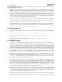
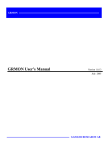
The resulting RTEMS executables are in elf format and has three main segments; text, data and bss. The
text segment is by default at address 0x40000000 for LEON2/3/4 and 0x2000000 for ERC32, followed
immediately by the data and bss segments. The LEON4 NGMP designs has RAM at 0x00000000, the qngmp compiler switch selects correct linker script for NGMP systems. The stack starts at top-of-ram and
extends downwards.
Figure 2.1. RCC RAM applications memory map
The SPARC trap table always occupies the first 4 Kbytes of the .text segment.
The LEON BSPs auto-detects end-of-ram by looking at the stack pointer provided by the bootloader or
GRMON at early boot. Hence the heap will be sized by the loader.
2.7. Board-support packages (BSPs)
RCC includes board-support packages for LEON2, LEON3 and ERC32. LEON4 is supported by the LEON3
BSP. BSPs provide interface between RTEMS and target hardware through initialization code specific to
target processor and a number of device drivers. Console and timer drivers are supported for all processors.
LEON2 and ERC32 BSPs assume a default system resource configuration such as memory mapping of onchip devices and usage of interrupt resources. LEON3/4 systems are based on GRLIB Plug & Play configuration, and are thereby highly configurable regarding memory mapping and interrupt routing. At start-up,
the LEON3 BSP scans the system bus to obtain system configuration information. Device drivers support a
number of devices which are automatically recognized, initiated and handled by the device drivers.
RCC User's Manual
8
2.7.1. LEON3 BSP
The LEON3 BSP includes two different console and timer drivers, standard (official RTEMS) drivers (qleon3std) and drivers which rely on the driver manager. The latter drivers are possible to configure from the
project configuration using standard driver manager configuration options, for example which APBUART
device is mapped to /dev/console and which timer is used as system clock one needs to configure for
AMP systems.
The console drivers supports APBUARTs. The first UART is registered under name /dev/console,
second and third UARTs get names /dev/console_b and dev/console_c and so on. LEON3 BSP
requires at least one APBUART.
The timer driver uses General Purpose Timer (GPT). The driver handles GPT timer 0 and the lowest interrupt request line used by GPT. GPT timer 0 and lowest request line should never be used by an RTEMS
application. If an application needs to use more timers GPT should be configured to have two or more timers
using separate request lines. Timer 0 interrupt can not be shared with other devices or GPT timers 1-6.
For more information on how to configure a system based on GRLIB see GRLIB IP Library User's Manual.
2.7.2. NGMP BSP
NGMP systems are supported by the LEON3 BSP and a custom linker script. The NGMP linker script is
selected using the -qngmp flag to the gcc during compiling and linking.
2.8. Driver Manager
The LEON3 BSP uses an optional Driver Manger that handles drivers and devices on the AMBA and PCI
Plug & Play buses. The drivers are automatically assigned with one or more hardware devices. The Driver
Manager is either initilized by the user from the Init() thread after RTEMS as started up, or during startup of
RTEMS. The LEON3 BSP has by default (-qleon3 and -qleon3mp) the driver manager enabled (--drvmgr
was given to configure during compiletime) that means that no extra initialization calls from Init() is needed,
however which drivers to be included must be configured uniquely per project. One can use -qleon3std to
avoid using the driver manager. In most cases the GPTIMER and the APBUART drivers are required to boot.
If the driver manager was configured to be initialized by the BSP, the RTEMS_DRVMGR_STARTUP
define is defined. If not configured the define is not set and the user can choose to initialize the driver
manager manually from for example the Init() task or not use it at all.
LEON2 systems are divided into two different systems, standard LEON2 systems and GRLIB-LEON2 systems where the AMBA Plug & Play bus is available. Both systems can use the LEON2 hardcoded bus with
the Driver Manager, however it's primary intention is to provide a root bus for a second bus supporting Plug
& Play. For example a GRLIB-LEON2 system has hardcoded peripherals (the standard LEON2 peripherals)
and GRLIB cores attached available from the AMBA Plug & Play information, the setup for a system like
that would be a LEON2 hardcoded bus and a LEON2 AMBA Plug & Play sub bus. Once the AMBA Plug
& Play bus is initialized all device and their drivers can be used the same way as in LEON3/4 systems.
For AT697 PCI systems the driver manager can be used to scan the PCI bus.
The ERC32 BSP does not support the driver manager.
2.8.1. Initialization
Regardless when the manager is initialized the following steps must be taken, however RTEMS and the BSP
takes all steps during startup for us when --drvmgr was passed to configure.
Before the driver manager is initialized one must register a root bus driver so that the driver manager
knows which bus to start search for devices at. The driver manager itself must also be initialized by calling
drvmgr_init() before any driver supporting the driver manager can be accessed. The manager replaces
the DRIVER_register() calls used in previous releases of RTEMS to register drivers.
RCC User's Manual
9
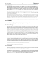
2.8.2. Configuration
The driver manager is configured by defining the array drvmgr_drivers, it contains one function pointer
per driver that is responsible to register one or more drivers. The drvmgr_drivers can be set up by defining
CONFIGURE_INIT, selecting the appropriate drivers and including drvmgr/drvmgr_confdefs.h.
The approach is similar to configuring a standard RTEMS project using rtems/confdefs.h. Below is
an example how to select drivers.
#include <rtems.h>
#define CONFIGURE_INIT
#include <bsp.h>
/* Standard RTEMS setup */
#define CONFIGURE_APPLICATION_NEEDS_CONSOLE_DRIVER
#define CONFIGURE_APPLICATION_NEEDS_CLOCK_DRIVER
#define CONFIGURE_RTEMS_INIT_TASKS_TABLE
#define CONFIGURE_MAXIMUM_DRIVERS
#include <rtems/confdefs.h>
32
/* Driver manager setup */
#if defined(RTEMS_DRVMGR_STARTUP)
/* if --drvmgr was given to configure (-qleon3, -qleon3mp) include GPTIMER and APBUART drivers
* that rely on the driver manager
*/
#define CONFIGURE_DRIVER_AMBAPP_GAISLER_GPTIMER
#define CONFIGURE_DRIVER_AMBAPP_GAISLER_APBUART
#endif
#define
#define
#define
#define
#define
#define
#define
#define
#define
#define
CONFIGURE_DRIVER_AMBAPP_GAISLER_GRETH
CONFIGURE_DRIVER_AMBAPP_GAISLER_GRSPW
CONFIGURE_DRIVER_AMBAPP_GAISLER_GRCAN
CONFIGURE_DRIVER_AMBAPP_GAISLER_OCCAN
CONFIGURE_DRIVER_AMBAPP_MCTRL
CONFIGURE_DRIVER_AMBAPP_GAISLER_PCIF
CONFIGURE_DRIVER_AMBAPP_GAISLER_GRPCI
CONFIGURE_DRIVER_PCI_GR_RASTA_IO
CONFIGURE_DRIVER_PCI_GR_RASTA_TMTC
CONFIGURE_DRIVER_PCI_GR_701
#include <drvmgr/drvmgr_confdefs.h>
The timer and console driver must be included when the driver manager is initialized on startup, whereas
the standard drivers are included automatically by the standard (-qleon3std) BSP setup.
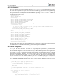
2.8.3. Driver configuration
In the past the driver resources were often a string interpreted by the driver passed into the
DRIVER_register() function. Since the register functions have been replaced the driver resource format has also been changed, it is now described by an array of different data types which are assigned names
for flexibility. The name is searched for by the driver once started, if found the value replaces the default
value internal to the driver. The driver uses a driver resource API to easily extract the information. The
resources are provided by the bus driver, it is up to the bus driver how the resources are assigned to the
bus, the LEON bus drivers use a default weak array that can be overridden by the project configuration.
The driver parameters are documented separately for each driver in the driver manual. The example below
sets up GRSPW0 and GRSPW1 descriptor count driver resources for the AMBA Plug & Play bus on two
different GR-RASTA-IO PCI boards and the root bus.
/* ROOT AMBA PnP Bus: GRSPW0 and GRSPW1 resources */
struct drvmgr_key grlib_grspw01_res[] =
{
{"txDesc", KEY_TYPE_INT, {(unsigned int)32}},
{"rxDesc", KEY_TYPE_INT, {(unsigned int)32}},
KEY_EMPTY
};
/* If RTEMS_DRVMGR_STARTUP is defined we override the "weak defaults" that
* is defined by the LEON3 BSP.
*/
struct drvmgr_bus_res grlib_drv_resources =
{
.next = NULL,
.resource = {
{DRIVER_AMBAPP_GAISLER_GRSPW_ID, 0, &grlib_grspw01_res[0]},
{DRIVER_AMBAPP_GAISLER_GRSPW_ID, 1, &grlib_grspw01_res[0]},
RES_EMPTY
RCC User's Manual
10
},
};
#ifndef RTEMS_DRVMGR_STARTUP
struct grlib_config grlib_bus_config = {
&ambapp_plb,/* AMBAPP bus setup */
&grlib_drv_resources,/* Driver configuration */
};
#endif
/* GR-RASTA-IO 0: GRSPW0 resources */
struct drvmgr_key rastaio0_grspw0_res[] = {
{"txDesc", KEY_TYPE_INT, {(unsigned int)8}},
{"rxDesc", KEY_TYPE_INT, {(unsigned int)32}},
KEY_EMPTY
};
/* GR-RASTA-IO 1: GRSPW1 resources */
struct drvmgr_key rastaio0_grspw0_res[] = {
{"txDesc", KEY_TYPE_INT, {(unsigned int)16}},
{"rxDesc", KEY_TYPE_INT, {(unsigned int)16}},
KEY_EMPTY
};
/* GR-RASTA-IO 1: GRSPW0 and GRPSW1 resources use same configuration */
struct drvmgr_key rastaio1_grspw01_res[] = {
{"txDesc", KEY_TYPE_INT, {(unsigned int)16}},
{"rxDesc", KEY_TYPE_INT, {(unsigned int)64}},
KEY_EMPTY
};
/*** Driver resources for GR-RASTA-IO 0 AMBA PnP bus ***/
struct drvmgr_bus_res gr_rasta_io0_res = {
.next = NULL,
.resource = {
{DRIVER_AMBAPP_GAISLER_GRSPW_ID, 0, &rastaio0_grspw0_res[0]},
{DRIVER_AMBAPP_GAISLER_GRSPW_ID, 1, &rastaio0_grspw1_res[0]},
RES_EMPTY
},
};
/*** Driver resources for GR-RASTA-IO 1 AMBA PnP bus ***/
struct drvmgr_bus_res gr_rasta_io1_res = {
.next = NULL,
.resource = {
{DRIVER_AMBAPP_GAISLER_GRSPW_ID, 0, &rastaio1_grspw01_res[0]},
{DRIVER_AMBAPP_GAISLER_GRSPW_ID, 1, &rastaio1_grspw01_res[0]},
RES_EMPTY
},
};
/* Tell GR-RASTA-IO driver about the bus resources.
* Resources for one GR-RASTA-IO board are available.
* AMBAPP->PCI->GR-RASTA-IO->AMBAPP bus resources
*
* The resources will be used by the drivers for the
* cores found on the GR-RASTA-IO->AMBAPP bus.
*
* The "weak defaults" are overriden here.
*/
struct drvmgr_bus_res *gr_rasta_io_resources[] = {
&gr_rasta_io0_res,/* GR-RASTA-IO board 1 resources */
&gr_rasta_io1_res,/* GR-RASTA-IO board 2 resources */
NULL,
/* End of table */
};
rtems_task Init( rtems_task_argument argument)
{
/* Manual driver manager initialization only required when driver manager not initialized during
* startup (-qleon2, -qleon3std)
*/
#ifndef RTEMS_DRVMGR_STARTUP
/* Register GRLIB root bus (LEON3/4) */
ambapp_grlib_root_register(&grlib_bus_config);
/* Initialize Driver Manager */
drvmgr_init();
#endif
...
RCC User's Manual
11
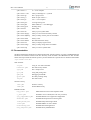
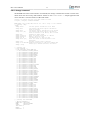
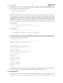
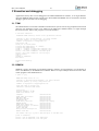
2.8.4. drvmgr command
The RTEMS shell comes with a number of commands, the drvmgr command can be used to extract information about the current setup and hardware. Please see the rtems-shell.c sample application that
comes with RCC. The rtems-shell on a GR712RC ASIC:
Creating /etc/passwd and group with three useable accounts
root/pwd , test/pwd, rtems/NO PASSWORD
RTEMS SHELL (Ver.1.0-FRC):dev/console. Oct 3 2011. ’help’ to list commands.
[/] # drvmgr --help
usage:
drvmgr buses
List bus specfic information on all buses
drvmgr devs
List general and driver specfic information
about all devices
drvmgr drvs
List driver specfic information on all drivers
drvmgr info [ID]
List general and driver specfic information
about all devices or one device, bus or driver
drvmgr mem
Dynamically memory usage
drvmgr parent ID
Short info about parent bus of a device
drvmgr remove ID
Remove a device or a bus
drvmgr res ID
List Resources of a device or bus
drvmgr short [ID]
Short info about all devices/buses or one
device/bus
drvmgr topo
Show bus topology with all devices
drvmgr tr ID OPT ADR Translate hw(0)/cpu(1) (OPT bit0) address ADR
down(0)/up(1) streams (OPT bit1) for device
drvmgr --help
[/] # drvmgr topo
--- BUS TOPOLOGY --|-> DEV 0x400fd3a0 GRLIB AMBA PnP
|-> DEV 0x400fd450 GAISLER_LEON3FT
|-> DEV 0x400fd4a8 GAISLER_LEON3FT
|-> DEV 0x400fd500 GAISLER_AHBJTAG
|-> DEV 0x400fd558 GAISLER_ETHMAC
|-> DEV 0x400fd5b0 GAISLER_SATCAN
|-> DEV 0x400fd608 GAISLER_SPW2
|-> DEV 0x400fd660 GAISLER_SPW2
|-> DEV 0x400fd6b8 GAISLER_SPW2
|-> DEV 0x400fd710 GAISLER_SPW2
|-> DEV 0x400fd768 GAISLER_SPW2
|-> DEV 0x400fd7c0 GAISLER_SPW2
|-> DEV 0x400fd818 GAISLER_B1553BRM
|-> DEV 0x400fd870 GAISLER_GRTC
|-> DEV 0x400fd8c8 GAISLER_GRTM
|-> DEV 0x400fd920 GAISLER_SLINK
|-> DEV 0x400fd978 GAISLER_FTMCTRL
|-> DEV 0x400fd9d0 GAISLER_APBMST
|-> DEV 0x400fd928 GAISLER_LEON3DSU
|-> DEV 0x400fd980 GAISLER_APBMST
|-> DEV 0x400fdb30 GAISLER_CANAHB
|-> DEV 0x400fdad8 GAISLER_CANAHB
|-> DEV 0x400fdb88 GAISLER_FTAHBRAM
|-> DEV 0x400fdbe0 GAISLER_APBUART
|-> DEV 0x400fdc38 GAISLER_IRQMP
|-> DEV 0x400fdc90 GAISLER_GPTIMER
|-> DEV 0x400fdce8 GAISLER_SPICTRL
|-> DEV 0x400fdd40 GAISLER_CANMUX
|-> DEV 0x400fdd98 NO_NAME
|-> DEV 0x400fddf0 GAISLER_ASCS
|-> DEV 0x400fde48 GAISLER_GPIO
|-> DEV 0x400fdea0 GAISLER_GPIO
|-> DEV 0x400fdef8 GAISLER_I2CMST
|-> DEV 0x400fdf50 GAISLER_CLKGATE
|-> DEV 0x400fdfa8 GAISLER_AHBSTAT
|-> DEV 0x400fe000 GAISLER_APBUART
|-> DEV 0x400fe058 GAISLER_APBUART
|-> DEV 0x400fe0b0 GAISLER_APBUART
|-> DEV 0x400fe108 GAISLER_APBUART
|-> DEV 0x400fe160 GAISLER_APBUART
|-> DEV 0x400fe1b8 GAISLER_GRTIMER
[/] # drvmgr info 0x400fdbe0
-- DEVICE 0x400fdbe0 -PARENT BUS: 0x400fd408
NAME:
GAISLER_APBUART
STATE:
0x00000100
INIT LEVEL: 4
ERROR:
0
MINOR BUS: 0
RCC User's Manual
12
MINOR DRV: 0
DRIVER:
0x400a2198 (APBUART_DRV)
PRIVATE:
0x400fe210
--- DEVICE INFO FROM BUS DRIVER --AMBA PnP DEVICE
VENDOR ID:
0x0001 (VENDOR_GAISLER)
DEVICE ID:
0x000c (GAISLER_APBUART)
IRQ:
2
VERSION:
0x1
ambapp_core: 0x400fdc1c
interfaces: APBSLV
APBSLV FREQ: 80000kHz
apb: 0x80000100-0x800001ff
--- DEVICE INFO FROM DEVICE DRIVER --UART Mode:
TERMIOS_POLLED
STATUS REG: 0x100082
CTRL REG:
0x80000803
SCALER REG: 0x103 baud rate 38610
2.9. Network configuration
The LEON2/3 BSPs support two network devices: the Aeroflex Gaisler GRETH MAC and the LAN91C111.
The GRETH driver comes in two editions, one that needs the driver manager (in libbsp) to operate and the standard driver (in libchip). The driver manager dependent GRETH driver adds the network interface automatically to the rtems_bsdnet_config network interface configuration using
network_interface_add() function. The LAN91C111 chip cannot be found by Plug & Play so it
has to be manually set up by either hardcoding an entry in the rtems_bsdnet_config interface list
or dynamically registered by calling network_interface_add(). The LAN91C111 attach routine is
defined by RTEMS_BSP_NETWORK_DRIVER_ATTACH_SMC91111 in bsp.h. The standard GRETH
device is setup in a similar way, see bsp.h.
See src/samples/rtems-ttcp.c for sample a networking application.
2.10. PCI
Aeroflex Gaisler provides a PCI Library together with RTEMS located in cpukit/libpci in the soruces. The
documentation for the PCI Library is located in the RTEMS documentation doc/usr/libpci.t and
available prebuilt into PDF named c_user.pdf, see Section 1.5.
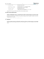
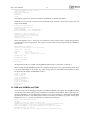
The RTEMS shell has been extended with a pci command can be used to extract information about the
current setup and hardware. Please see the [rtems-shell.c] sample application that comes with RCC. A nonPCI system:
reating /etc/passwd and group with three useable accounts
root/pwd , test/pwd, rtems/NO PASSWORD
RTEMS SHELL (Ver.1.0-FRC):dev/console. Oct 3 2011. ’help’ to list commands.
[/] # pci --help
usage:
pci ls [bus:dev:fun|PCIID]
List one or all devices
pci r{8|16|32} bus:dev:fun OFS
Configuration space read
pci r{8|16|32} PCIID OFS
Configuration space read
access by PCIID
pci w{8|16|32} bus:dev:fun OFS D Configuration space write
pci w{8|16|32} PCIID OFS D
Configuration space write
access by PCIID
pci pciid bus:dev:fun
Print PCIID for bus:dev:fun
pci pciid PCIID
Print bus:dev:fun for PCIID
pci pcfg
Print current PCI config for
static configuration library
pci getdev {PCIID|bus:dev:fun}
Get PCI Device from RAM tree
pci infodev DEV_ADR
Info about a PCI RAM Device
pci --help
[/] # pci
SYSTEM:
CFG LIBRARY:
NO. PCI BUSES:
PCI ENDIAN:
MACHINE ENDIAN:
UNKNOWN / UNINITIALIZED
AUTO
0 buses
Little
Big
RCC User's Manual
13
2.11. Making boot-proms
RTEMS applications are linked to run from beginning of RAM. To make a boot-PROM that will run from the
PROM on a standalone target, use the mkprom2 utility freely available from www.gaisler.com. The mkprom
utility is documented in a separate document that is distributed together with the mkprom2 utility. Mkprom
will create a compressed boot image that will load the application into RAM, initiate various processor
registers, and finally start the application. Mkprom will set all target dependent parameters, such as memory
sizes, wait-states, baudrate, and system clock. The applications do not set these parameters themselves, and
thus do not need to be re-linked for different board architectures.
The example below creates a LEON3 boot-prom for a system with 1 Mbyte RAM, one waitstate during
write, 3 waitstates for rom access, and 40 MHz system clock. For more details see the mkprom manual
$ mkprom2 -ramsz 1024 -ramwws 1 -romws 3 hello.exe -freq 40 hello.exe
Note that mkprom creates binaries for LEON2/3 and for ERC32, select processor type with the mkprom
options -leon3, -leon2 or -erc32 flag. To create an SRECORD file for a prom programmer, use objcopy:
$ sparc-rtems-objcopy -O srec rtems-hello rtems-hello.srec
2.12. Simple examples
Following example compiles the famous "hello world" program and creates a boot-prom in SRECORD
format:
bash-2.04$ sparc-rtems-gcc -mcpu=v8 -msoft-float -O2 rtems-hello.c -o rtems-hello
bash-2.04$ mkprom2 -leon3 -freq 40 -dump -baud 38400 -ramsize 1024 -rmw rtems-hello
bash-2.04$ sparc-rtems-objcopy -O srec rtems-hello rtems-hello.srec
bash-2.04$
Several example C programs can be found in /opt/rtems-4.10/src/samples.
2.13. Multiprocessing
RTEMS supports asymmetric multiprocessing (AMP), the LEON3 BSP supports AMP in two different setups. Either the RTEMS kernel is compiled with multiprocessing support (-qleon3mp) or the user setup
custom resource sharing with driver manager resources (-qleon3), the difference is that RTEMS provide
multiprocessing objects and communication channels in the former case and in the latter case the user is
responsible for all synchronization itself which in many cases are sufficient. All nodes in a asymmetric multiprocessor system executes thier own program image. Messages are passed between the nodes containing
synchronization information, for example take global semaphore A. Messages are sent over memory using
the Shared Memory Support Driver in the LEON3 BSP, and interrupts are used to alert the receiving CPU.
The kernel must be compiled with multiprocessing support in order for the RTEMS AMP support to be
available, the toolchain includes a precompiled LEON3 MP kernel in rtems-4.10/sparc-rtems/
leon3mp, it is the LEON3 BSP compiled with multiprocessing support. The MP kernel is selected when
the [-qleon3mp] argument is given to sparc-rtems-gcc.
Since each CPU executes its own program image, a memory area has to be allocated for each CPU's program
image and stack. This is achieved by linking each CPU's RTEMS program at the start addresses of the
CPU's memory area and setting stack pointer to the top of the memory area. E.g. for two CPU system, the
application running on CPU 0 could run in memory area 0x40100000 - 0x401fffff, while CPU 1 runs in
memory area 0x4020000 - 0x402fffff. Shared Memory Support Driver allocates 4 KB buffer at address
0x40000000 for message passing (this area can not be used for applications).
Each CPU requires its own set of standard peripherals such as UARTs and timers. In an MP system the BSP
will automatically allocate UART 1 and GPT 0 timer 1 to CPU 0, UART 2 and GPT 0 timer 2 to CPU 1 and
so on. When the default configuration does not meet the requirements or hardware setup a custom resource
allocation can be setup using the driver manager, see below.
The shared memory driver's default memory layout configuration can be overidden without recompiling the
kernel. The default settings are set in the variable weak variable BSP_shm_cfgtbl, it can be overridden
RCC User's Manual
14
by defining BSP_shm_cfgtbl once in the project as in the below example. The parameters that has an
effect in changing is the fields base and length.
/* Override default SHM configuration */
shm_config_table BSP_shm_cfgtbl = {
.base = (void *)0x40000000,
.length = 0x00010000
};
Hardware resource allocation is done by the BSP for UART, IRQ controller and System Clock Timer.
Devices which has a driver that is implemented using the driver manager can be ignored by a specific CPU
by assigning the keys value NULL in the driver resouces. The driver manager simply ignores the device
when a NULL resource is detect. An example is given below where CPU0 is assigned GRGPIO0 and CPU1
GRGPIO1. GPTIMER driver have options that limit number of timers and which timer is used for system
clock, the system console and debug output can be selected to a specific UART with the APBUART driver.
CPU0 Application:
struct rtems_drvmgr_drv_res grlib_drv_resources[] =
{
{DRIVER_AMBAPP_GAISLER_GRGPIO_ID, 1, NULL} /* Used by CPU1 */
};
CPU1 Application:
struct rtems_drvmgr_drv_res grlib_drv_resources[] =
{
{DRIVER_AMBAPP_GAISLER_GRGPIO_ID, 0, NULL}, /* Used by CPU0 */
{DRIVER_AMBAPP_GAISLER_GRGPIO_ID, 1, &grlib_drv_res_grgpio1[0]}
};
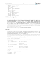
Following example shows how to run RTEMS MP application on a two CPU system using GRMON. CPU 0
executes image node1.exe in address space 0x6000000 - 0x600fffff while CPU 1 executes image node2.exe
in address space 0x60100000 - 0x601fffff.
GRMON LEON debug monitor v1.1.22
Copyright (C) 2004,2005 Gaisler Research - all rights reserved.
For latest updates, go to http://www.gaisler.com
Comments or bug-reports to [email protected]
...
grlib> lo node1.exe
section: .text at 0x60000000, size 143616 bytes
section: .data at 0x60023100, size 3200 bytes
total size: 146816 bytes (174.4 kbit/s)
read 852 symbols
entry point: 0x60000000
grlib> lo node2.exe
section: .text at 0x60100000, size 143616 bytes
section: .data at 0x60123100, size 3200 bytes
total size: 146816 bytes (172.7 kbit/s)
read 852 symbols
entry point: 0x60100000
grlib> cpu act 0
active cpu: 0
grlib> ep 0x60000000
entry point: 0x60000000
grlib> stack 0x600fff00
stack pointer: 0x600fff00
grlib> cpu act 1
active cpu: 1
grlib> ep 0x60100000
entry point: 0x60100000
grlib> stack 0x601fff00
stack pointer: 0x601fff00
grlib> cpu act 0
active cpu: 0
grlib> run
RTEMS MP applications can not be run directly in GRSIM (using load and run commands). Instead a boot
image containing several RTEMS MP applications should be created and simulated.
2.13.1. MP testsuite
The MP testsuite is located in the sources under testsuite/mptests, it requires modifications to the
make scripts in order to select a unique image RAM location. The default shared memory area is at
RCC User's Manual
15
0x40000000-0x40000fff, the two images for node1 and node2 needs to be located on a unique address and
the heap/stack must also fit. The argument -Wl,- Ttext,0x40001000 for node1 and -Wl,-Ttext,0x40200000
for node2 can be added to the link stage, and the entry point (0x40001000 and 0x40200000) and stacks
(0x401ffff0 and 0x403ffff0) must also be set by the loader (GRMON or mkprom for example). Depending
on where the RAM memory is located and how much memory is available the paramters may vary.
RCC User's Manual
16
3. Execution and debugging
Applications built by RCC can be debugged on the TSIM LEON/ERC32 simulator, or on target hardware
using the GRMON debug monitor (LEON only). Both TSIM and GRMON can be connected to the GNU
debugger (gdb) for full source-level debugging.
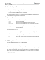
3.1. TSIM
The TSIM simulator can emulate a full ERC32 and LEON2/3 system with on-chip peripherals and external
memories. For full details on how to use TSIM, see the TSIM User's Manual. Below is a simple example
that shows how the ‘hello world’ program is run in the simulator:
$ tsim-leon3 rtems-hello
TSIM/LEON3 SPARC simulator, version 2.0.4a (professional version)
Copyright (C) 2001, Gaisler Research - all rights reserved.
For latest updates, go to http://www.gaisler.com/
Comments or bug-reports to [email protected]
using 64-bit time
serial port A on stdin/stdout
allocated 4096 K RAM memory, in 1 bank(s)
allocated 2048 K ROM memory
icache: 1 * 4 kbytes, 16 bytes/line (4 kbytes total)
dcache: 1 * 4 kbytes, 16 bytes/line (4 kbytes total)
section: .text, addr: 0x40000000, size 92096 bytes
section: .data, addr: 0x400167c0, size 2752 bytes
read 463 symbols
tsim> go
resuming at 0x40000000
Hello World
Program exited normally.
tsim>
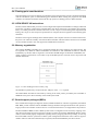
3.2. GRMON
GRMON is used to download, run and debug LEON2/3 software on target hardware. For full details on
how to use GRMON, see the GRMON User' Manual. Below is a simple example that shows how the "hello
world" program is downloaded and run:
$ grmon -u -jtag
GRMON LEON debug monitor v1.1.11
Copyright (C) 2004,2005 Gaisler Research - all rights reserved.
For latest updates, go to http://www.gaisler.com/
Comments or bug-reports to [email protected]
using JTAG cable on parallel port
JTAG chain: xc3s1500 xcf04s xcf04s
initialising ............
detected frequency: 41 MHz
GRLIB build version: 1347
Component
LEON3 SPARC V8 Processor
AHB Debug UART
AHB Debug JTAG TAP
GR Ethernet MAC
LEON2 Memory Controller
AHB/APB Bridge
LEON3 Debug Support Unit
Nuhorizons Spartan3 I/O interfac
OC CAN controller
Generic APB UART
Multi-processor Interrupt Ctrl
Modular Timer Unit
Aeroflex
Aeroflex
Aeroflex
Aeroflex
Aeroflex
European
Aeroflex
Aeroflex
Aeroflex
Aeroflex
Aeroflex
Aeroflex
Aeroflex
Gaisler
Gaisler
Gaisler
Gaisler
Gaisler
Space Agency
Gaisler
Gaisler
Gaisler
Gaisler
Gaisler
Gaisler
Gaisler
Use command ’info sys’ to print a detailed report of attached cores
grlib> lo rtems-hello
section: .text at 0x40000000, size 92096 bytes
section: .data at 0x400167c0, size 2752 bytes
RCC User's Manual
17
total size: 94848 bytes (339.7 kbit/s)
read 463 symbols
entry point: 0x40000000
grlib> run
Hello World
grlib>
Note that the program was started from address 0x40000000, the default start address.
GRMON can also be used to program the boot-PROM image created by sparc-rtems-mkprom into the
target’s flash PROM.
grmon[grlib]> flash unlock all
grmon[grlib]> flash erase all
Erase in progress
Block @ 0x00000000 : code = 0x00800080 OK
Block @ 0x00004000 : code = 0x00800080 OK
...
grmon[grlib]> flash load prom.out
section: .text at 0x0, size 54272 bytes
total size: 54272 bytes (93.2 kbit/s)
read 45 symbols
grmon[grlib]> flash lock all
When boot-PROM is run (i.e. after reset) it will initialize various LEON registers, unpack the application
to the RAM and start the application. The output on console when running “hello world” from PROM is
shown below:
MkProm LEON3 boot loader v1.2
Copyright Gaisler Research - all right reserved
system clock
baud rate
prom
sram
:
:
:
:
40.0 MHz
38352 baud
512 K, (2/2) ws (r/w)
1024 K, 1 bank(s), 0/0 ws (r/w)
decompressing .text
decompressing .data
starting rtems-hello
Hello World
The application must be re-loaded with the load command before it is possible to re-execute it.
When running multiple RTEMS programs on a multiprocessing system, entry point and stack pointer have
to be set up individually for each CPU. E.g. when running app1.exe (link address 0x40100000) on CPU0
and app2.exe (link address 0x40200000) on CPU1:
grlib>
grlib>
grlib>
grlib>
grlib>
grlib>
grlib>
grlib>
grlib>
grlib>
lo app1.exe
lo app1.exe
cpu act 0
ep 0x40100000
stack 0x401fff00
cpu act 1
ep 0x40200000
stack 0x402fff00
cpu act 0
run
3.3. GDB with GRMON and TSIM
To perform source-level debugging with gdb, start TSIM or GRMON with -gdb or enter the gdb command
at the prompt. Then, attach gdb by giving command "tar extended-remote localhost:2222" to gdb when connecting to GRMON or "tar extended-remote localhost:1234" when connecting to TSIM. Note that RTEMS
applications do not have a user-defined main() function necessarily as ordinary C-programs. Instead, put a
breakpoint on Init(), which is the default user-defined start-up function.
jupiter> sparc-rtems-gdb rtems-hello
GNU gdb 6.7.1
Copyright (C) 2007 Free Software Foundation, Inc.
License GPLv3+: GNU GPL version 3 or later <http://gnu.org/licenses/gpl.html>
This is free software: you are free to change and redistribute it.
There is NO WARRANTY, to the extent permitted by law. Type "show copying"
and "show warranty" for details.
This GDB was configured as "--host=i686-pc-linux-gnu --target=sparc-rtems".
RCC User's Manual
18
(gdb) tar extended-remote localhost:2222
Remote debugging using localhost:2222
(gdb) load
Loading section .text, size 0x164e0 lma 0x40000000
Loading section .jcr, size 0x4 lma 0x400164e0
Loading section .data, size 0xaa8 lma 0x400164e8
Start address 0x40000000, load size 94092
Transfer rate: 57902 bits/sec, 277 bytes/write.
(gdb) break Init
Breakpoint 2 at 0x400011f8: file rtems-hello.c, line 33.
(gdb) run
The program being debugged has been started already.
Start it from the beginning? (y or n) y
Starting program: /opt/rtems-4.10/src/samples/rtems-hello
Breakpoint 2, Init (ignored=0) at rtems-hello.c:33
33
printf("Hello World\n");
(gdb) cont
Continuing.
Hello World
Program exited with code 0363.
The application must be re-loaded with the load command before it is possible to re-execute it.
3.4. Using DDD graphical front-end to gdb
DDD is a graphical front-end to gdb, and can be used regardless of target. The DDD graphical debugger is
freely available from http://www.gnu.org/software/ddd. To start DDD with the sparc-rtems-gdb debugger
do:
ddd --debugger sparc-rtems-gdb
The required gdb commands to connect to a target can be entered in the command window. See the GDB
and DDD manuals for how to set the default settings. If you have problems with getting DDD to run, run
it with -- check-configuration to probe for necessary libraries etc. DDD has many advanced features, see
the on-line manual under the 'Help' menu.
On windows/cygwin hosts, DDD must be started from an xterm shell. First launch the cygwin X-server by
issuing 'startx' in a cygwin shell, and the launch DDD in the newly created xterm shell.
RCC User's Manual
19
4. Support
For Support, contact the Aeroflex Gaisler support team at [email protected].
RCC User's Manual
20
5. Disclaimer
Aeroflex Gaisler AB, reserves the right to make changes to any products and services described herein at any
time without notice. Consult Aeroflex or an authorized sales representative to verify that the information in
this document is current before using this product. Aeroflex does not assume any responsibility or liability
arising out of the application or use of any product or service described herein, except as expressly agreed
to in writing by Aeroflex; nor does the purchase, lease, or use of a product or service from Aeroflex convey
a license under any patent rights, copyrights, trademark rights, or any other of the intellectual rights of
Aeroflex or of third parties.