1
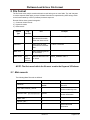
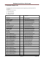
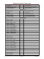
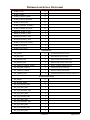
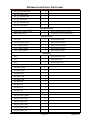
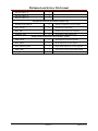
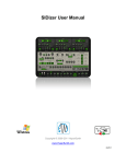
Load & Save File Format
Additional products from
Counters
Frequency Meters
PID Controllers
Clock/Timers
Printers
Process Meters
On/Off
Controllers
Recorders
Relative
Humidity
Transmitters
Thermocouples
Thermistors
Wire
Wireless
Rate Meters
Timers
Totalizers
Strain Gauge
Meters
Voltmeters
Multimeters
Soldering Iron
Testers
pH pens
pH Controllers
pH Electrodes
RTDs
Thermowells
Flow Sensors
For Immediate Assistance
In the U.S.A. and Canada: 1-800-NEWPORT®
In Mexico: (95) 800-NEWPORTSM
Or call your local NEWPORT Office.
The information contained in this document is believed to be correct but NEWPORT Electronics, Inc. accepts
no liability for any errors it contains, and reserves the right to alter specifications without notice.
WARNING: These products are not designed for use in, and should not be used for, patient connected applications.
Trademark Notice:
,
NEWPORT, NEWPORT®, and newportUS.com are trademarks of NEWPORT
Electronics, Inc.
This device is marked with the international caution symbol. It is important to read the Setup Guide before
installing or commissioning this device as it contains important information relating to safety and EMC.
®
®
Newport Electronics, Inc. www.newportUS.com
2229 South Yale Street [email protected]
Santa Ana, CA 92704
Platinum Load & Save File Format
Table of Contents
1
Introduction ........................................................................................................... 2
1.1
1.2
1.3
2
Purpose ....................................................................................................................2
Definition of Terms and Acronyms ........................................................................2
Applicable Documents ............................................................................................3
File Format ............................................................................................................ 4
2.1
2.1.1
2.2
2.3
2.3.1
2.3.2
2.4
Meta records ............................................................................................................4
User Meta-records................................................................................................................. 5
Comments................................................................................................................5
Data records ............................................................................................................5
Item Field ............................................................................................................................... 5
Value Field ............................................................................................................................ 5
Device Configuration Records ...............................................................................5
Revision 0.1
Page 1 of 15
Platinum Load & Save File Format
1 Introduction
1.1 Purpose
The following document defines the file format used by the Platinum series Load and Save
commands.
The Save command is intended to capture the configuration of a Platinum series controller and save
it on removable media (ie: USB Stick memory).
The Load command is intended to read a configuration image from an external device (ie: USB
memory stick) and store it on a Platinum device.
The file format used is an ASCII text file, with tab delimiters between each field. These files may be
reviewed or modified using a simple text editor or application programs such as Microsoft Excel that
support reading tab delimited files.
1.2 Definition of Terms and Acronyms
I2C
2 wire serial interface
Base Device
Device connected to slave device
Smart Input
Device supporting 1 or more Input sensors
Smart Output
Device supporting 1 or more Output Elements
Sensor Element
One of the physical sensing elements on a Smart Output
AC
Alternating Current
DC
Direct Current
CS
Chip Select
ADC
Analog to Digital Converter
DAC
Digital to Analog Converter
RS485
Electrical signals used for serial communications
RS232
Electrical signals used for serial communications
CSV
Comma Separated Values
COTS
Commercially-Off-The-Shelf
ESD
Electo Static Discharge
FW
Firmware
HW
Hardware
I/O
Input/Output
LED
Light Emitting Diode
Hexadecimal
Values expressed using base 16 (24)
Revision 0.1
Page 2 of 15
Platinum Load & Save File Format
1.3 Applicable Documents
Doc. #
Name / Description
Rev. #, Date
Device Serialization and Version Information
Rev 0.1
Omega Engineering Coding Standard
Rev 1.2.0
Revision 0.1
Page 3 of 15
Platinum Load & Save File Format
2 File Format
The file format uses multiple records with each record having one or more fields. The ‘tab’ character
is used to separate fields within a record. All data information is represented by ASCII strings. Each
record is terminated by a CR/LF (0xd/0xa) character sequence.
Records fall into three general categories:
1) Comment / blank records
2) Keyword records
3) Data records
Record
Type
Tag
character
Use
Example
Meta Record
%
Defines
operations/information
other than data records
%File <tab> Platinum_0000.txt
Comment
//
Allow users to insert
comments to document
files
// This is a comment
Blank Line
Data record
Allow separating blocks
of information
<any
printable
character>
Defines data to be read
or written
INPUT_SENSOR <tab> 2
NOTE: The first record within the file must contain the Keyword %Platinum.
2.1 Meta records
The following Meta Records are defined:
Meta Record
%Platinum
%File <tab> Platinum_xxxx.txt
%Version <tab> yyy.yyyy.yyyy.yyy
%Date <tab> …
%Author <tab> …
%DeviceID <tab> xxxxxxxxx
Load Function
Save Function
Must be first record in
the file
Generated as first record
in the file
Ignored
Generated based on file
number entered by user
Ignored
Records device F/W
version information
Ignored
Not generated
Ignored
Not generated
Ignored
Generated based on
internal DeviceID
information
Revision 0.1
Page 4 of 15
Platinum Load & Save File Format
%Profile <tab> xx
%Segment <tab> xx
%<user defined> <tab> ????
Saves current Profile
information and starts
loading new R&S profile
Saves current segment
information and starts
loading new R&S segment
Ignored
Generated, xx = 00-99
Generated, xx = 1..8
Ignored
2.1.1 User Meta-records
Additional meta-records may be defined by the user. Upon loading, they will be ignored and the data
will not be retained. User meta-records are not generated during the Save function.
Future versions of Platinum f/w may include support for Date Created, Date Loaded, Author and other
meta-record information.
2.2 Comments
All text following a double slash (//) will be ignored. Users may add comment information on blocks of
records on individual records following the data field.
Note that load function stops parsing the record after the data field has been captured. Extraneous
characters following the data field will be ignored.
Blank records (lines) are ignored.
2.3 Data records
Data records consist of 2 fields, an item and a value, separated by a tab character.
Item <tab> Value
2.3.1 Item Field
The item field provides a named field from the device data base.
During the load operation unrecognized items will be ignored. This allows configuration files to be
maintained across versions that introduce expanded items.
2.3.2 Value Field
The value field will be generate as either a floating point value (xx.x) or an unsigned 32 bit integer
(xx). The parser will process all characters up to the first non-numeric character.
2.4 Device Configuration Records
Device Configuration records allow loading data that enable / disable specific device features.
Device Configuration records may only be written when the device serialization mechanism is in the
write enable state. During a Load operation these records are ignored device serialization
mechanism is not in the write enable state.
During the Save operation all Device Configuration records as written to the file.
Revision 0.1
Page 5 of 15
Platinum Load & Save File Format
2.5 Example File (Partial Excel)
Revision 0.1
Page 6 of 15
Platinum Load & Save File Format
3 Parameter Name List
The following table summarizes all parameter names supported by the LOAD and SAVE file
commands.
The data TYPE column key is:
L – long (32 bit) integer
R – short (16 bit) integer
F – floating point value
Description
Mnemonic
Type
DEVICE_ID
L
Device Identifier
VERSION_NUMBER
L
Device Version (xxx.xxx.xxx.xxx)
INPUT_SENSOR
R
Enumerated sensor (input) type
TC_TYPE
R
Enumerated Thermocouple type
RTD_WIRE
R
Enumerated RTD wire type
RTD_ACRV_OHM_TYPE
R
Enumerated RTD Curve
THERMISTOR_VALUE
R
Enumerated Thermistor type
PROCESS_RANGE
R
Enumerated process input range
INPUT_SENSOR
R
Enumerated sensor (input) type
TC_TYPE
R
Enumerated Thermocouple type
RTD_WIRE
R
Enumerated RTD wire type
DB_4_20_MANUAL_LIVE
R
Enumerated Input Process mode
DB_4_20_MANUAL_READING_1
F
Manual Scale reading value 1
DB_4_20_MANUAL_INPUT_1
F
Manual Scale input value 1
DB_4_20_MANUAL_READING_2
F
Manual Scale reading value 2
DB_4_20_MANUAL_INPUT_2
F
Manual Scale input value 2
DB_4_20_LIVE_READING_1
F
Live Scale reading value 1
DB_4_20_LIVE_INPUT_1
F
Live Scale input value 1
DB_4_20_LIVE_READING_2
F
Live Scale reading value 2
DB_4_20_LIVE_INPUT_2
F
Live Scale input value 2
DB_0_24_MANUAL_LIVE
R
DB_0_24_MANUAL_READING_1
F
DB_0_24_MANUAL_INPUT_1
F
DB_0_24_MANUAL_READING_2
F
DB_0_24_MANUAL_INPUT_2
F
DB_0_24_LIVE_READING_1
F
Revision 0.1
Page 7 of 15
Platinum Load & Save File Format
DB_0_24_LIVE_INPUT_1
F
DB_0_24_LIVE_READING_2
F
DB_0_24_LIVE_INPUT_2
F
DB_10_MANUAL_LIVE
R
DB_10_MANUAL_READING_1
F
DB_10_MANUAL_INPUT_1
F
DB_10_MANUAL_READING_2
F
DB_10_MANUAL_INPUT_2
F
DB_10_LIVE_READING_1
F
DB_10_LIVE_INPUT_1
F
DB_10_LIVE_READING_2
F
DB_10_LIVE_INPUT_2
F
DB_1_MANUAL_LIVE
R
DB_1_MANUAL_READING_1
F
DB_1_MANUAL_INPUT_1
F
DB_1_MANUAL_READING_2
F
DB_1_MANUAL_INPUT_2
F
DB_1_LIVE_READING_1
F
DB_1_LIVE_INPUT_1
F
DB_1_LIVE_READING_2
F
DB_1_LIVE_INPUT_2
F
DB_POINT_1_MANUAL_LIVE
R
DB_POINT_1_MANUAL_READING_1
F
DB_POINT_1_MANUAL_INPUT_1
F
DB_POINT_1_MANUAL_READING_2
F
DB_POINT_1_MANUAL_INPUT_2
F
DB_POINT_1_LIVE_READING_1
F
DB_POINT_1_LIVE_INPUT_1
F
DB_POINT_1_LIVE_READING_2
F
DB_POINT_1_LIVE_INPUT_2
F
READING_DECIMAL_POSITION
R
Enumerated value – number of dec. points
DISPLAY_UNITS
R
Enumerated value – units of measure
Revision 0.1
Page 8 of 15
Platinum Load & Save File Format
DISPLAY_COLOR_NORMAL
R
Enumerated value to set display color
DISPLAY_BRIGHTNESS
R
Enumerated value to set display brightness
DB_ANNUNCIATOR_1_MODE
R
DB_ANNUNCIATOR_2_MODE
R
READING_FILTER_CONSTANT
R
Enumerated input filtering constant
EXCITATION_VOLTAGE
R
Enumerated excitation control value
USB_PROTOCOL
R
USB_RECOGNITION_CHARACTER
R
USB_DATA_FLOW
R
USB_ECHO_MODE
R
USB_CONTINUOUS_DATA_PERIOD
F
USB_DATA_FORMAT_STATUS
R
USB_DATA_FORMAT_READING
R
USB_DATA_FORMAT_PEAK
R
USB_DATA_FORMAT_VALLEY
R
USB_DATA_FORMAT_UNIT
R
USB_SEPARATION_CHAR
R
USB_LINE_FEED
R
USB_DEVICE_ADDRESS
R
USB_MODBUS_MODE
R
USB_MODBUS_EOF
R
ETH_PROTOCOL
R
ETH_RECOGNITION_CHARACTER
R
ETH_DATA_FLOW
R
ETH_ECHO_MODE
R
ETH_CONTINUOUS_DATA_PERIO
F
ETH_DATA_FORMAT_STATUS
R
ETH_DATA_FORMAT_READING
R
ETH_DATA_FORMAT_PEAK
R
ETH_DATA_FORMAT_VALLEY
R
ETH_DATA_FORMAT_UNIT
R
ETH_LINE_FEED
R
Revision 0.1
Page 9 of 15
Platinum Load & Save File Format
ETH_SEPARATION_CHAR
R
ETH_DEVICE_ADDRESS
R
ETH_MODBUS_MODE
R
ETH_MODBUS_EOF
R
SERIAL_PROTOCOL
R
SERIAL_RECOGNITION_CHARAC
R
SERIAL_DATA_FLOW
R
SERIAL_ECHO_MODE
R
SERIAL_CONTINUOUS_DATA_PE
R
SERIAL_DATA_FORMAT_STATUS
F
SERIAL_DATA_FORMAT_READIN
R
SERIAL_DATA_FORMAT_PEAK
R
SERIAL_DATA_FORMAT_VALLEY
R
SERIAL_DATA_FORMAT_UNIT
R
SERIAL_LINE_FEED
R
SERIAL_SEPARATION_CHAR
R
SERIAL_DEVICE_ADDRESS
R
SERIAL_MODBUS_MODE
R
SERIAL_MODBUS_EOF
R
SERIAL_232_485
R
SERIAL_BAUD_RATE
R
SERIAL_PARITY
R
SERIAL_DATABITS
R
SERIAL_STOPBITS
R
Safety Parameters
TIME_FORMAT
R
Enumerated value to indicate time format
SAFETY_DELAYED_POWER_ON_RUN
R
Write 1 to DISABLE auto RUN on power up
SAFETY_DELAYED_OPER_RUN
R
Write 1 to DISABLE return to RUN in OPER
SAFETY_SETPOINT_LIMIT_LOW
F
Minimum allowed setpoint value
SAFETY_SETPOINT_LIMIT_HIGH
F
Maximum allowed setpoint value
LOOP_BREAK_ENABLE
R
Write 1 to enable loop break test
LOOP_BREAK_TIME
L
Time (msec) for break test
OPEN_CIRCUIT_ENABLE
R
Write 1 to enable open circuit test
Passwords
PASSWORD_INIT_ENABLE
R
Revision 0.1
Write 1 to enable INIT menu password
Page 10 of 15
Platinum Load & Save File Format
PASSWORD_INIT
L
INIT menu password
PASSWORD_PROGRAM_ENABLE
R
Write 1 to enable PROG menu password
PASSWORD_PROGRAM
L
PROG menu password
Setpoint Control
SETPOINT_1_MODE
R
Enumerated Setpoint 1 mode
SETPOINT_1
F
Setpoint 1 value
SETPOINT_2_MODE
R
Enumerated Setpoint 2 mode
ABSOLUTE_SETPOINT_2
F
Setpoint 2 value (absolute mode)
DEVIATION_SETPOINT_2
F
Setpoint 2 value (derivative mode)
Output Configuration
OUTPUT_1_HW_TYPE
R
OUTPUT_1_MODE
R
OUTPUT_1_ON_OFF_ACTION
R
OUTPUT_1_SETPOINT
R
OUTPUT_1_PULSE_LENGTH
F
OUTPUT_1_ON_OFF_DEADBAND
F
OUTPUT_1_OUTPUT_RANGE
R
OUTPUT_1_RETRAN_READING_1
F
OUTPUT_1_RETRAN_OUTPUT_1
F
OUTPUT_1_RETRAN_READING_2
F
OUTPUT_1_RETRAN_OUTPUT_2
F
OUTPUT_2_HW_TYPE
R
OUTPUT_2_MODE
R
OUTPUT_2_ON_OFF_ACTION
R
OUTPUT_2_SETPOINT
R
OUTPUT_2_PULSE_LENGTH
F
OUTPUT_2_ON_OFF_DEADBAND
F
OUTPUT_2_OUTPUT_RANGE
R
OUTPUT_2_RETRAN_READING_1
F
OUTPUT_2_RETRAN_OUTPUT_1
F
OUTPUT_2_RETRAN_READING_2
F
OUTPUT_2_RETRAN_OUTPUT_2
F
OUTPUT_3_HW_TYPE
R
OUTPUT_3_MODE
R
Revision 0.1
Page 11 of 15
Platinum Load & Save File Format
OUTPUT_3_ON_OFF_ACTION
R
OUTPUT_3_SETPOINT
R
OUTPUT_3_PULSE_LENGTH
F
OUTPUT_3_ON_OFF_DEADBAND
F
OUTPUT_3_OUTPUT_RANGE
R
OUTPUT_3_RETRAN_READING_1
F
OUTPUT_3_RETRAN_OUTPUT_1
F
OUTPUT_3_RETRAN_READING_2
F
OUTPUT_3_RETRAN_OUTPUT_2
F
OUTPUT_4_HW_TYPE
R
OUTPUT_4_MODE
R
OUTPUT_4_ON_OFF_ACTION
R
OUTPUT_4_SETPOINT
R
OUTPUT_4_PULSE_LENGTH
F
OUTPUT_4_ON_OFF_DEADBAND
F
OUTPUT_4_OUTPUT_RANGE
R
OUTPUT_4_RETRAN_READING_1
F
OUTPUT_4_RETRAN_OUTPUT_1
F
OUTPUT_4_RETRAN_READING_2
F
OUTPUT_4_RETRAN_OUTPUT_2
F
Alarm Control
ALARM_1_TYPE
R
ALARM_1_MODE
R
ALARM_1_DISPLAY_COLOR
R
ALARM_1_HIGH_HIGH_MODE
R
ALARM_1_LATCH_TYPE
R
ALARM_1_CONTACT_CLOSURE_T
R
ALARM_1_POWER_ON_STATE
R
ABSOLUTE_ALARM_1_LOW
F
ABSOLUTE_ALARM_1_HIGH
F
DEVIATION_ALARM_1_LOW
F
DEVIATION_ALARM_1_HIGH
F
ALARM_1_HIGH_HIGH_OFFSET
F
ALARM_1_ON_DELAY
F
ALARM_1_OFF_DELAY
F
Revision 0.1
Page 12 of 15
Platinum Load & Save File Format
ALARM_2_TYPE
R
ALARM_2_MODE
R
ALARM_2_DISPLAY_COLOR
R
ALARM_2_HIGH_HIGH_MODE
R
ALARM_2_LATCH_TYPE
R
ALARM_2_CONTACT_CLOSURE_T
R
ALARM_2_POWER_ON_STATE
R
ABSOLUTE_ALARM_2_LOW
F
ABSOLUTE_ALARM_2_HIGH
F
DEVIATION_ALARM_2_LOW
F
DEVIATION_ALARM_2_HIGH
F
ALARM_2_HIGH_HIGH_OFFSET
F
ALARM_2_ON_DELAY
F
ALARM_2_OFF_DELAY
F
PID Parameters
PID_ACTION
R
Enumerated PID control action
PID_MAX_RATE
F
PID maximum rate of change
PID_PERCENT_LOW
F
Minimum PID Control output value
PID_PERCENT_HIGH
F
Maximum PID Control output value
PID_ADAPTIVE_CONTROL_ENABLE
R
Write 1 to enable Adaptive Control
PID_AUTOTUNE_TIMEOUT
L
Timeout (msec) for autotuning
PID_ STABILITY_TIMEOUT
L
Autotune stability test timeout
PID_ STABILITY_RATE
F
Autotune maximum rate of change stability test
Remote Setpoint Group
RSP_ENABLE
R
RSP_PROCESS_RANGE
R
RSP_4_20_SETPOINT_MIN
F
RSP_4_20_INPUT_MIN
F
RSP_4_20_SETPPOINT_MAX
F
RSP_4_20_INPUT_MAX
F
RSP_0_24_SETPOINT_MIN
F
RSP_0_24_INPUT_MIN
F
RSP_0_24_SETPPOINT_MAX
F
RSP_0_24_INPUT_MAX
F
RSP_0_10_SETPOINT_MIN
F
RSP_0_10_INPUT_MIN
F
Revision 0.1
Page 13 of 15
Platinum Load & Save File Format
RSP_0_10_SETPOINT_MAX
F
RSP_0_10_INPUT_MAX
F
RSP_0_1_SETPOINT_MIN
F
RSP_0_1_INPUT_MIN
F
RSP_0_1_SETPOINT_MAX
F
RSP_0_1_INPUT_MAX
F
Ramp & Soak Control
RAMP_SOAK_PROFILE_SELECT
R
Starting Profile for Ramp and Soak
RAMP_SOAK_MODE
R
Enumerated – Ramp and Soak mode
Calibration Group
TCAL_TYPE
R
Enumerated TCAL type
TCAL_ICE_POINT_OFFSET
F
Stored ICE POINT offset
TCAL_1_POINT_OFFSET
F
Stored 1 point CAL offset
TCAL_2_POINT_OFFSET
F
Stored 2 point CAL offset
TCAL_2_POINT_GAIN
F
Stored 2 point CAL gain
PID Tuning
PID_P_
F
Proportional Gain value
PID_I_
F
Integral Gain value
PID_D_
F
Derivative Gain value
Simulation Group
SIM_INPUT_MODE
R
SIM_INPUT_RATE
R
SIM_INPUT_ADJ
F
SIM_INPUT_MAX
F
SIM_INPUT_MIN
F
SIM_INPUT_C0
F
SIM_INPUT_C1
F
SIM_INPUT_C2
F
SIM_INPUT_C3
F
SIM_AUX_INPUT_MODE
R
SIM_AUX_INPUT_RATE
R
SIM_AUX_INPUT_ADJ
F
SIM_AUX_INPUT_MAX
F
SIM_AUX_INPUT_MIN
F
SIM_AUX_INPUT_C0
F
Revision 0.1
Page 14 of 15
Platinum Load & Save File Format
SIM_AUX_INPUT_C1
F
SIM_AUX_INPUT_C2
F
SIM_AUX_INPUT_C3
F
Ramp & Soak Profile Info (repeated for profiles 1..99)
SEGMENTS_PER_PROFILE
R
Number of segments in current profile
SOAK_ACTION
R
Enumerated – Soak Action
SOAK_LINK
R
Profile to link to after current profile
TRACKING_TYPE
R
Enumerated – R&S tracking type
Ramp & Soak Segment Info (repeated 8 times / profile)
RAMP_EVENT
R
RE.ON flag set for current segment
SOAK_EVENT
R
SE.ON flag set for current segment
SOAK_PROCESS_VALUE
F
Target SOAK setpoint for current segment
RAMP_TIME
L
Time (msec) to reach target SOAK setpoint
SOAK_TIME
L
Time (msec) to hold at SOAK setpoint
Revision 0.1
Page 15 of 15
Warranty/Disclaimer
NEWPORT Electronics, Inc. warrants this unit to be free of defects in materials and workmanship for a period of one
(1) year from the date of purchase. In addition to NEWPORT’s standard warranty period, NEWPORT Electronics
will extend the warranty period for four (4) additional years if the warranty card enclosed with each instrument is
returned to NEWPORT.
If the unit should malfunction, it must be returned to the factory for evaluation. NEWPORT’s Customer Service
Department will issue an Authorized Return (AR) number immediately upon phone or written request. Upon
examination by NEWPORT, if the unit is found to be defective it will be repaired or replaced at no charge.
NEWPORT’s WARRANTY does not apply to defects resulting from any action of the purchaser, including but not
limited to mishandling, improper interfacing, operation outside of design limits, improper repair, or unauthorized
modification. This WARRANTY is VOID if the unit shows evidence of having been tampered with or shows evidence
of being damaged as a result of excessive corrosion; or current, heat, moisture or vibration; improper specification;
misapplication; misuse or other operating conditions outside of NEWPORT’s control. Components which wear are
not warranted, including but not limited to contact points, fuses, and triacs.
NEWPORT is pleased to offer suggestions on the use of its various products. However, NEWPORT neither
assumes responsibility for any omissions or errors nor assumes liability for any damages that result from
the use of its products in accordance with information provided by NEWPORT, either verbal or written.
NEWPORT warrants only that the parts manufactured by it will be as specified and free of defects.
NEWPORT MAKES NO OTHER WARRANTIES OR REPRESENTATIONS OF ANY KIND WHATSOEVER,
EXPRESSED OR IMPLIED, EXCEPT THAT OF TITLE, AND ALL IMPLIED WARRANTIES INCLUDING
ANY WARRANTY OF MERCHANTABILITY AND FITNESS FOR A PARTICULAR PURPOSE ARE HEREBY
DISCLAIMED. LIMITATION OF LIABILITY: The remedies of purchaser set forth herein are exclusive and
the total liability of NEWPORT with respect to this order, whether based on contract, warranty, negligence,
indemnification, strict liability or otherwise, shall not exceed the purchase price of the component upon
which liability is based. In no event shall NEWPORT be liable for consequential, incidental or special
damages.
CONDITIONS: Equipment sold by NEWPORT is not intended to be used, nor shall it be used: (1) as a “Basic
Component” under 10 CFR 21 (NRC), used in or with any nuclear installation or activity; or (2) in medical
applications or used on humans. Should any Product(s) be used in or with any nuclear installation or activity, medical
application,
or
used
on
humans,
or
misused
in
any
way,
NEWPORT
assumes
no
responsibility
as
set
forth
in
our
basic
WARRANTY / DISCLAIMER language, and additionally purchaser will indemnify NEWPORT and hold NEWPORT
harmless from any liability or damage whatsoever arising out of the use of the Product(s) in such a manner.
Return Requests/Inquiries
Direct all warranty and repair requests/inquiries to the NEWPORT Customer Service Department. BEFORE
RETURNING ANY PRODUCT(S) TO NEWPORT, PURCHASER MUST OBTAIN AN AUTHORIZED
RETURN (AR) NUMBER FROM NEWPORT’S CUSTOMER SERVICE DEPARTMENT (IN ORDER TO AVOID
PROCESSING DELAYS). The assigned AR number should then be marked on the outside of the return package
and on any correspondence.
The purchaser is responsible for shipping charges, freight, insurance and proper packaging to prevent breakage in
transit.
FOR WARRANTY RETURNS, please have the
following information available BEFORE
contacting NEWPORT:
1. P.O. number under which the product was
PURCHASED,
2. Model and serial number of the product under
warranty, and
3. Repair instructions and/or specific problems
relative to the product.
FOR NON-WARRANTY REPAIRS, consult NEWPORT
for current repair charges. Have the following
information available BEFORE contacting NEWPORT:
1. P.O. number to cover the COST of
the repair,
2. Model and serial number of product, and
3. Repair instructions and/or specific problems relative
to the product.
NEWPORT’s policy is to make running changes, not model changes, whenever an improvement is possible.
This affords our customers the latest in technology and engineering.
NEWPORT is a registered trademark of NEWPORT Electronics, Inc. Patent pending.
© Copyright 2015 NEWPORT Electronics, Inc. All rights reserved. This document may not be copied, photocopied, reproduced, translated, or reduced to any electronic medium or machine-readable form,
in whole or in part, without prior written consent of NEWPORT Electronics, Inc.
M5457/N/0315