1
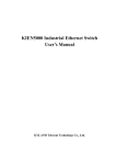
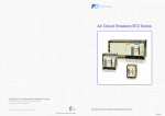
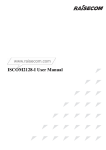
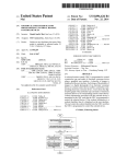
www.raisecom.com ISCOM2110-I User Manual Legal Notices Raisecom Technology Co., Ltd makes no warranty of any kind with regard to this manual, including, but not limited to, the implied warranties of merchantability and fitness for a particular purpose. Raisecom Technology Co., Ltd shall not be held liable for errors contained herein or direct, indirect, special, incidental or consequential damages in connection with the furnishing, performance, or use of this material. Warranty. A copy of the specific warranty terms applicable to your Raisecom product and replacement parts can be obtained from Service Office. Restricted Rights Legend. All rights are reserved. No part of this document may be photocopied, reproduced, or translated to another language without the prior written consent of Raisecom Technology Co., Ltd. The information contained in this document is subject to change without notice. Copyright Notices. Copyright ©2011 Raisecom. All rights reserved. No part of this publication may be excerpted, reproduced, translated or utilized in any form or by any means, electronic or mechanical, including photocopying and microfilm, without permission in Writing from Raisecom Technology Co., Ltd. Trademark Notices is the trademark of Raisecom Technology Co., Ltd. Java™ is a U.S. trademark of Sun Microsystems, Inc. Microsoft® is a U.S. registered trademark of Microsoft Corporation. Windows NT® is a U.S. registered trademark of Microsoft Corporation. Windows® 2000 is a U.S. registered trademark of Microsoft Corporation. Windows® XP is a U.S. registered trademark of Microsoft Corporation. Windows® and MS Windows® are U.S. registered trademarks of Microsoft Corporation. Contact Information Technical Assistance Center The Raisecom TAC is available to all customers who need technical assistance with a Raisecom product, technology, or, solution. You can communicate with us through the following methods: Address: Building 2, No. 28 of the Shangdi 6th Street, Haidian District, Beijing 100085 Tel: +86-10-82883305 Fax: +86-10-82883056 World Wide Web You can access the most current Raisecom product information on the World Wide Web at the following URL: http://www.raisecom.com Feedback Comments and questions about how the ISCOM2110-I device works are welcomed. Please review the FAQ in the related manual, and if your question is not covered, send email by using the following web page: http://www.raisecom.com/en/contact-us.html. If you have comments on the ISCOM2110-I specification, instead of the web page above, please send comments to: [email protected] We hope to hear from you! CONTENTS Chapter 1 Product Overview ------------------------------------------------------------------------ 1 1.1 1.2 Content overview ------------------------------------------------------------------------------------------------------ 1 Terms explanation ---------------------------------------------------------------------------------------------------- 1 2.1 2.2 2.3 Device hardware description --------------------------------------------------------------------------------------- 2 Device dimension ----------------------------------------------------------------------------------------------------- 2 Device operating environment ------------------------------------------------------------------------------------- 2 3.1 Device front panel description -------------------------------------------------------------------------------------- 3 4.1 Device installation ----------------------------------------------------------------------------------------------------- 6 Chapter 2 Chapter 3 Chapter 4 4.1.1 4.1.2 4.2 Device Appearance ---------------------------------------------------------------------- 3 Installation And Application----------------------------------------------------------- 6 Environment requirement --------------------------------------------------------------------------------------------------------- 6 Installing on rack or hanging on wall-------------------------------------------------------------------------------------------- 6 Connection of the switch -------------------------------------------------------------------------------------------- 6 4.2.1 4.2.2 4.2.3 4.2.4 4.3 4.4 Specifications And Dimensions ------------------------------------------------------ 2 Connect to CONSOLE------------------------------------------------------------------------------------------------------------- 6 Connect to Ethernet ---------------------------------------------------------------------------------------------------------------- 7 Connect to the power supply ----------------------------------------------------------------------------------------------------- 8 Connect to alarm port-------------------------------------------------------------------------------------------------------------- 9 Cable making ---------------------------------------------------------------------------------------------------------- 9 Electrify the device --------------------------------------------------------------------------------------------------- 10 Chapter 5 Cautions------------------------------------------------------------------------------------ 11 General Safety Instructions The following instructions serve as a general guide for the safe installation and operation of telecommunications products. Additional instructions, if applicable, are included inside the manual. Safety Symbols This symbol may appear on the equipment or in the text. It indicates potential safety hazards regarding product operation or maintenance to operator or service personnel. Danger of electric shock! Avoid any contact with the marked surface while the product is energized or connected to outdoor telecommunication lines. Protective earth: the marked lug or terminal should be connected to the building protective earth bus. Some products have terminals which are permanently protective earthing conductors. Please be sure well connected to earthing before equipment connected to supply. Some products may be equipped with a laser diode. In such cases, a label with the laser class and other warnings as applicable will be attached near the optical transmitter. The laser warning symbol may be also attached. Please observe the following precautions: • Before turning on the chassis with optic module, make sure that the fiber optic cable is intact and is connected to the transmitter. • Do not attempt to adjust the laser drive current. • Do not use broken or unterminated fiber-optic cables/connectors or look straight at the laser beam. • The use of optical devices with the equipment will increase eye hazard. • Use of controls, adjustments or performing procedures other than those specified herein, may result in hazardous radiation exposure. ATTENTION: The laser beam may be invisible! Always observe standard safety precautions during installation, operation and maintenance of this product. Only qualified and authorized service personnel should carry out adjustment, maintenance or repairs to this product. No installation, adjustment, maintenance or repairs should be performed by either the operator or the user. Some products have more than one power supply cord. Disconnect 2 power supply cords before servicing to avoid electric shock. Before operating modules in the electricity conditions, please be noticed that optical modules shall be connected with optical fiber wires or shield with optical module cover for fear that laser light harms to operator’s eyes. It is suggested to apply optical module CLASS1 as laser. Handling Energized Products General Safety Practices Do not touch or tamper with the power supply when the power cord is connected. Line voltages may be present inside certain products even when the power switch (if installed) is in the OFF position or a fuse is blown. For DC-powered products, although the voltages levels are usually not hazardous, energy hazards may still exist. Before working on equipment connected to power lines or telecommunication lines, remove jewelry or any other metallic object that may come into contact with energized parts. Unless otherwise specified, all products are intended to be grounded during normal use. Grounding is provided by connecting the mains plug to a wall socket with a protective earth terminal. If an earth lug is provided on the product, it should be connected to the protective earth at all times, by a wire with a diameter of 18 AWG or wider. Rack-mounted equipment should be mounted only in earthed racks and cabinets. Always make the ground connection first and disconnect it last. Do not connect telecommunication cables to ungrounded equipment. Make sure that all other cables are disconnected before disconnecting the ground. Connection of AC Mains Make sure that the electrical installation complies with local codes. Always connect the AC plug to a wall socket with a protective ground. Always connect the power cord first to the equipment and then to the wall socket. If a power switch is provided in the equipment, set it to the OFF position. If the power cord cannot be readily disconnected in case of emergency, make sure that a readily accessible circuit breaker or emergency switch is installed in the building installation. Connection of DC Mains Unless otherwise specified in the manual, the DC input to the equipment is floating in reference to the ground. Any single pole can be externally grounded. Due to the high current capability of DC mains systems, care should be taken when connecting the DC supply to avoid short-circuits and fire hazards. DC units should be installed in a restricted access area, i.e. an area where access is authorized only to qualified service and maintenance personnel. Make sure that the DC supply is electrically isolated from any AC source and that the installation complies with the local codes. Before connecting the DC supply wires, ensure that power is removed from the DC circuit. Locate the circuit breaker of the panel board that services the equipment and switch it to the OFF position. When connecting the DC supply wires, first connect the ground wire to the corresponding terminal, then the positive pole and last the negative pole. Switch the circuit breaker back to the ON position. A readily accessible disconnect device that is suitably rated and approved should be incorporated in the building installation. Preventing Electrostatic Discharge Damage Modules which can be plugged into chassis are sensitive to damage from static electricity. Conversely, static voltages as high as 35,000V can be generated just by handling plastic or foam packing material, or by sliding assemblies across plastic and carpets. Not exercising the proper electrostatic discharge (ESD) precautions can result in intermittent or complete component failures. To minimize the potential for ESD damage, observe the following guidelines: • Always use an ESD-preventive antistatic wrist strap or ankle strap and ensure that it makes good skin contact. • When removing or installing a component, make sure the equipment end of your antistatic strap leash is connected to the ESD connection sockets on the front of the chassis or to a bare metal surface on the chassis. Avoid contact between the component and your clothing. The wrist strap only protects the component from ESD voltages on the body; ESD voltages on your clothing can still cause component damage. • Always place a card component-side-up on an antistatic surface, in an antistatic card rack, or in a static shielding bag. If you are returning the item to the factory, immediately place it in a static shielding bag. • Handle Modules by the metal card carrier edges only; Avoid touching the board or any connector pins. Preface About This Manual This manual is available for ISCOM2110-I VER A.00 and higher versions. . Who Should Read This Manual This manual is a valuable reference for sales and marketing staff, after service staff and telecommunication network designers. For those who want to have an overview of the features, applications, structure and specifications of ISCOM2110-I device, this is also a recommended document. Relevant Manuals ISCOM2110-I Commands Notebook ISCOM2110-I Configuration Guide Organization This manual is an introduction of the main functions of ISCOM2110-I device. Please read this manual carefully. The manual is composed of the following chapters: Chapter 1 Product Overview This chapter briefly introduces the related reference documents and explains related glossary. Chapter 2 Specifications and Dimensions This chapter mainly introduces the device specification, dimensions and operating environment. Chapter 3 Device Appearance This chapter focuses on device panel and indicator description. Chapter 4 Installation and Application This chapter introduces the cables and sub-cards used during device installation. Chapter 5 Cautions This chapter brings forth the detailed requirements besides device during installation. Compliance The RC series products developed by Raisecom are strictly complied with the following standards as well as ITU-T, IEEE, IETF and related standards from other international telecommunication standard organizations: YD/T900-1997 SDH Equipment Technical Requirements - Clock YD/T973-1998 SDH 155Mb/s and 622Mb/s Technical conditions of optical transmitter module and receiver module YD/T1017-1999 Network node interface for the Synchronous Digital Hierarchy (SDH) YD/T1022-1999 Requirement of synchronous digital hierarchy (SDH) equipment function YD/T1078-2000 SDH Transmission Network Technique Requirements-Interworking of Network Protection Architectures YD/T1111.1-2001 Technical Requirements of SDH Optical Transmitter/Optical Receiver Modules——2.488320 Gb/s Optical Receiver Modules YD/T1111.2- 2001 Technical Requirements of SHD Optical Transmitter/Optical Receiver Modules——2.488320 Gb/s Optical Transmitter Modules YD/T1179- 2002 Technical Specification of Ethernet over SDH G.703 Physical/electrical characteristics of hierarchical digital interfaces G.704 Synchronous frame structures used at 1544, 6312, 2048, 8448 and 44 736 kbit/s hierarchical levels G.707 Network node interface for the synchronous digital hierarchy (SDH) G.774 Synchronous digital hierarchy (SDH) - Management information model for the network element view G.781 Synchronization layer functions G.783 Characteristics of synchronous digital hierarchy (SDH) equipment functional blocks G.784 Synchronous digital hierarchy (SDH) management G.803 Architecture of transport networks based on the synchronous digital hierarchy (SDH) G.813 Timing characteristics of SDH equipment slave clocks (SEC) G.823 The control of jitter and wander within digital networks which are based on the 2048 kbit/s hierarchy G.825 The control of jitter and wander within digital networks which are based on the synchronous digital hierarchy (SDH) G.826 End-to-end error performance parameters and objectives for international, constant bit-rate digital paths and connections G.828 Error performance parameters and objectives for international, constant bit-rate synchronous digital paths G.829 Error performance events for SDH multiplex and regenerator sections G.831 Management capabilities of transport networks based on the synchronous digital hierarchy (SDH) G.841 Types and characteristics of SDH network protection architectures G.842 Interworking of SDH network protection architectures G.957 Optical interfaces for equipments and systems relating to the synchronous digital hierarchy G.691 Optical interfaces for single channel STM-64 and other SDH systems with optical amplifiers G.664 Optical safety procedures and requirements for optical transport systems I.731 ATM Types and general characteristics of ATM equipment I.732 ATM Functional characteristics of ATM equipment IEEE 802.1Q Virtual Local Area Networks (LANs) IEEE 802.1p Traffic Class Expediting and Dynamic Multicast Filtering IEEE 802.3 CSMA/CD Access Method and Physical Layer Instruction www.raisecom.com User Manual Chapter 1 Product Overview 1.1 Content overview This manual mainly discusses the installation of ISCOM2110-I switch. It describes features of the device, introduces its components and the functions these components accomplish. The manual brings forth a normative installation procedure for users and explains the types and specifications of all cables applied during the installation. This manual focuses on the hardware installation and employment of ISCOM2110-I device. For the configuration and operations of the switch based on software, please refer to the corresponding software configuration guide and commands notebook. 1.2 Terms explanation 10BASE-T A short term in IEEE 802.3 for Ethernet over CAT-3 or better twisted pair, based on Manchester coding and running at 10Mbps. 100BASE-TX A short term in IEEE 802.3 for Fast Ethernet over CAT-5 twisted pair, based on 4B/5B coding and running at100Mbps. The auto-negotiation procedure is: the port at one site adapts its bit rate and duplex mode to Auto-Negotiation the highest level that the opposite site device both support according to the bit rate and duplex mode adopted by the remote site device, that is, the connected devices on both sites adopt the fastest transmission mode they both support after the auto-negotiation process. Full-Duplex A communication pattern that allows Tx and Rx date in both directions simultaneously. Half-Duplex A communication pattern that allows Tx and Rx date in both directions, but only one direction at one time. RJ-45 The 8-pin modular connector applied in twisted pair cable link MDI Medium Dependent Interface, the name for the connector physically and electrically connects the media converter and the media segment. MDIX Medium Dependent Interface Crossover, it sends the transmitting signal of a device to the receiving port of the opposite device and vice versa. 1 www.raisecom.com User Manual Chapter 2 Specifications And Dimensions 2.1 Device hardware description ISCOM2110-I is a kind of layer-2 Ethernet switch specially designed for the access to industrial communication network. The device provides 6 10/100Base-TX Ethernet interfaces, 2 100Base-FX SFP optical interfaces, as well as 2 100Base-FX/1000Base-X auto-negotiation SFP optical interfaces. System power is smaller than 10W. 2.2 Device dimension Dimension of device: 146mm (W) x 130mm (D) x 59mm (H). Net weight: 1.1 kg ISCOM2110-I can be placed not only in the industrial field or on device rack in machine room, but also by hanging board to tighten on the wall. 2.3 Device operating environment Working environment: Environment temperature: -40°C ~ +85°C Storage temperature: - 40°C ~ +85°C Environment humidity: 5% ~ 95% 2 www.raisecom.com User Manual Chapter 3 Device Appearance 3.1 Device front panel description On the front panel of ISCOM2110-I switch, there are 10 Ethernet ports and indicators; 1 console port and 1 power supply indicator on the side, as well as 1 alarm terminal. G2 G1 100/1000M 7 PWR1 PWR2 LNK/ACT 8 LNK/ACT ALM RUN TX G2 RX 110/220V 24/48V ISCOM2110-I TX G1 RX + +/L - PWR1 TX PE 8 - PWR2 7 PE PE TX -/N + RX RX ALM 5 6 3 4 1 CONSOLE LNK/ACT 2 10M/100M Note: 1. Logo and model of the switch: RAISECOM ISCOM2110-I 2. System operation and optical interface working status indicators: ALARM, RUN, PWR1, PWR2, link/ACT7, link/ACT8, link/ACT-G1, link/ACT-G2, 100/1000M-G1, and 100/1000M-G2 (see the 3 www.raisecom.com User Manual panel) Indicator RUN ALM LNK/ACT7 LNK/ACT8 Color Green Status Description ON CPU is starting. Flickering Device is ready for working after finishes starting. OFF CPU cannot startup in order. ON Device has alarm. OFF Device doesn’t have alarm or rescovery. ON The interface is Link Up. Flickering The interface is transmitting or receiving data. OFF The interface is Link Down. ON The interface is Link Up. Flickering The interface is transmitting or receiving data. OFF The interface is Link Down. ON The interface is Link Up. Flickering The interface is transmitting or receiving data. OFF The interface is Link Down. ON The interface is Link Up. Flickering The interface is transmitting or receiving data. OFF The interface is Link Down. ON The interface is link up to Ethernet at speed of 1000M. OFF The interface is link up to Ethernet at speed of 100M. ON The interface is link up to Ethernet at speed of 1000M. OFF The interface is link up to Ethernet at speed of 100M. ON Power supply 1 is working in order. OFF Power supply 1 is not working. ON Power supply 2 is working in order. OFF Power supply 2 is not working. Green Green Green link/ACT-G1 Green link/ACT-G2 Green 100/1000M-G1 Green 100/1000M-G2 Green PWR1 PWR2 Green Green 3. 6 10/100M Ethernet ports and its corresponding indicators, each port corresponding to 2 indicators: LNK/ACT and 10/100 (specific corresponding relations refer to panel mark) 4 www.raisecom.com User Manual Indicator LNK/ACT 10/100 Color Green Status Description ON The interface is Link Up. Flickering The interface is transmitting or receiving data. OFF The interface is Link Down. ON The interface is link up to Ethernet at speed of 100M. OFF The interface is link up to Ethernet at speed of 10M. Yellow 4. CONSOLE interface: CONSOLE 5. Power and alarm interface 110/220V row corresponding three pins (+/L, -/N, PE) connect to DC110V or AC/DC220V voltage input. The specific operations are depending on the device type. 24/48V row corresponding six pins (+, -, PE, +, -, PE) connect to DC24V or DC48V voltage input . The specific operations are depending on the device type. The device is in support of dual-power supply redundant, and one power supply can also work normally. Note: This device cannot connect to the four voltage types as above at the same time. Before connecting to power, please carefully confirm device models, avoid faulty voltage, causing damage to the device. The 3-pin alarm terminals are sorted into normal open contact and normal closed contact, middle pin for public end. Attention when connecting alarm signal, it should not more than rated voltage and current: Max. voltage: 30VDC Max. current: 2A @ 30VDC Max. capacity: 60W 5 www.raisecom.com User Manual Chapter 4 Installation And Application 4.1 Device installation 4.1.1 Environment requirement There are heat exhaust outlets on three sides of ISCOM2110-I (VERA.00) while version above B.00 is an completely closed design. Internal fever relies mainly on the radiator for cooling circuit inside. Please leave space on both sides of the device to keep air flow unblocked. Please make sure the outlets are not blocked. 4.1.2 Installing on rack or hanging on wall The device accessories include DIN guide rail, user can install the switch direct on the prepared rail; if choosing hanging model, take some screws to install the device on the accessary hanging board. 4.2 Connection of the switch 4.2.1 Connect to CONSOLE ISCOM2110-I switch provides RS232C interface in form of RJ45 as Console interface. Connect the Console interface of ISCOM2110-I to serial port of PC by cable in accessories, then user can configure and manage the switch through PC Console. Signal definition of Console interface ISCOM2110-I switch adopts Console interface in form of RJ45. The pin arrangement shows as figure below: 1 8 PIN 1 PIN 8 RJ45 Socket RJ45 Connector The pin function definition of Console interface shows as below table: Pin Number Function Type 3 RxD input 6 TxD output 6 www.raisecom.com User Manual 4, 5 GND 1, 2, 7, 8 N.C Signal definition of PC serial port The 9-pin serial port on PC is corresponding to the below pin and definition: Pin No. Function 1 CD 2 RxD 3 TxD 4 DTR 5 GND Type Pin No. Function 6 DSR input 7 RTS output 8 CTS 9 RI Type Connection and parameters setting of CONSOLE interface CONSOLE interface of ISCOM2110-I is connected to PC serial port as below figure shows: 3 2 5 TxD RxD GND PC serial port TxD 6 RxD 3 GND 4, 5 ISCOM2110-I Console port Set parameters for PC terminal as below: Baud rate: 9600 Data bit: 8 Stop bit: 1 Parity bit: None Flow control: None 4.2.2 Connect to Ethernet ISCOM2110-I provides 6 10/100M auto-negotiation Ethernet interfaces port1-6, auto-negotiation funciton is enabled by default setting. Port7 and port8 are 100Base-FX SFP optical interfaces, port9 and port10 are 100Base-FX/1000Base-X auto-negotiation SFP optical interfaces. The Ethernet electrical interfaces of ISCOM2110-I have auto-MDI/MDIX function when auto-negotiation enable. That is to say, the switch can perform MDI and MDIX signal switchover. the device can communication in order regardless to the peer device adopts MDI or MDIX port, straight-through or crossover network cable. Please refer to section Console interface signal definition for pin arrangement of RJ45 connector and 7 www.raisecom.com User Manual socket. MDI and MDIX signal definition: Pin No. MDI-X signal MDI signal 1 RD+ TD+ 2 RD- TD- 3 TD+ RD+ 6 TD- RD- 4, 5, 7, 8 N.C N.C The Ethernet port adopts MDI-X signal when ISCOM2110-I Ethernet electrical port auto-negotiation function is disabled. User can use straight-through cable to connect with PC with MDI port. 4.2.3 Connect to the power supply Before connection ISCOM2110-I switch power, take care of confirmation for purchasing product model and related voltage types. According to device labeled, access appropriate power and voltage to corresponding pins position, otherwise it will damage device. The device is not compatible with the following four voltages input. ISCOM2110- I-12: DC12V dual-power supply; voltage input range for 9V ~18V ISCOM2110- I-24: DC24V dual-power supply; voltage input range for 18V ~ 36V ISCOM2110- I-48: DC48V dual-power supply; voltage input range for 6V ~72V 3 ISCOM2110- I-110: DC110V single-power supply; voltage input range for 66V ~ 160V ISCOM2110-I-220: AC/DC220V single-power supply; voltage input range for 85 ~ 264VAC; or 120 ~ 340VDC Note: The ISCOM2110-I doesn’t have independent switch for power supply. So the device is electrified once user connects the switch with power supply by power wire. Be noted to make sure the switch is connected correctly before connecting the power wire. DC110V equipment and AC/DC220V equipment connect to +/L, -/N, and PE if the power input has no PE signal. The PWR1 & PWR2 power interface on DC24V device should connect with +, -, PE respectively 8 www.raisecom.com User Manual 4.2.4 Connect to alarm port Parameters of failed alarm relay: Max. voltage: 30VDC Max. current: 2A @ 30VDC Max. capacity: 60W 4.3 Cable making 1) Straight through cable (The straight through cables for 100M and 1000M are identical.) Side 1 12 3 4 5 6 7 8 12 3 4 5 6 7 8 Side 2 Side 1 Side 2 1 = White/Orange 1 = White/Orange 2 = Orange 2 = Orange 3 = White/Green 3 = White/Green 4 = Blue 4 = Blue 5 = White/Blue 5 = White/Blue 6 = Green 6 = Green 7 = White/Brown 7 = White/Brown 8 = Brown 8 = Brown 2) 100M Crossover cable Side 1 12345678 12345678 Side 2 Side 1 Side 2 1 = White/Orange 1 = White/Green 2 = Orange 2 = Green 3 = White/Green 3 = White/Orange 4 = Blue 4 = Blue 5 = White/Blue 5 = White/Blue 6 = Green 6 = Orange 7 = White/Brown 7 = White/Brown 8 = Brown 8 = Brown 3) 1000M crossover cable 9 www.raisecom.com User Manual Side 1 1 2 3 4 5 6 78 12345678 Side 2 Side 1 Side 2 1 = white/orange 1 = white/green 2 = orange 2 = green 3 = white/green 3 = white/orange 4 = blue 4 = white/brown 5 = white/blue 5 = brown 6 = green 6 = orange 7 = white/brown 7 = blue 8 = brown 8 = white/blue 4.4 Electrify the device After installing the device following the steps above, connect power supply wire to electrify the device. After electrifying, the indicator PWR will turn ON to indicate that the power supply of the system is working. All the indicators on the the device will lighten to denote the device is performing self-checking and initialization. The device enters operating status after the self-check and initialization. The indicator of RUN starts to flicker, denoting system is working in order. Indicators of Ethernet interfaces will denote the status of each port (ON or OFF according to the port setting and connection). If user connect Console port of the switch to PC before electrifying and configure terminal software correct, the PC will display user management interface for user administration. Please refer to related ISCOM2110-I Series Switch Configuration Guide for details. 10 www.raisecom.com User Manual Chapter 5 Cautions The installation, maintenance, plugging in and pulling out of components of ISCOM2110-I switch can only be operated by qualified technical support staff. Please place the device in a temperature-controllable and humidity-controllable room and please be cautious of the conductivity of the materials around the device. Please note that a room with high humidity exposes the device to short circuit; while low humidity may lead to fire alarm. In a word, the switch must be placed in proper surroundings. The device shell should be well earthed to discharge static electricity. Please keep some distance from other powered devices when installing the device. Wire layout of the switch should intercross live wire, avoid close parallel in long distance. Please operate strictly following the instructions in this manual. Please avoid operating the device with wet hands or hands with too much sweat. Any mechanical and electrical modifications to the device are strictly forbidden. 11 Address: Building 2, No. 28 of the Shangdi 6th Street, Haidian District, Beijing Postcode: 100085 Tel: +86-10-82883305 F ax: +86-10-82883056 E mail: [email protected] http://www.raisecom.com