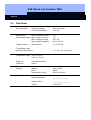
1
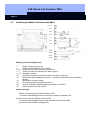
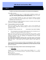
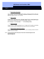
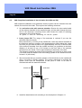
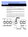
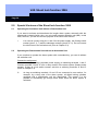
VdS Shunt lock function 3066
Version: December 2003
VdS Shunt lock function 3066
Register
Deactivation unit
Deactivation unit
Deactivation unit
Activation unit with
configuration
MASTER
Alarm System
1.0
2.0
Functional Description ________________________________4
1.1
General Information ______________________________________ 4
1.2
Safety Remarks __________________________________________ 6
Assembly Instructions_________________________________7
2.1
General Information on Installing the Components ____________ 7
2.2
Installing the Deactivation Unit (DA)_________________________ 8
2.2.1 Testing the Deactivation Unit (DA) __________________________ 9
2.2.2 Connecting Power Supply, Lock Contact Evaluation and
Sabotage Contacts: ______________________________________ 9
2.2.3 Connecting Deactivation Request and
eactivation Acknowledgement ____________________________ 10
2.3
Installing the Master Activation Unit (MA) ___________________ 11
2.3.1 Testing the Master Activation Unit (MA)_____________________ 12
2.3.2 Connecting Power Supply, Switch Contacts and
abotage Contacts: ______________________________________ 12
2.3.3 Connecting Deactivation Request, Deactivation
Acknowledgement and Activation Request _________________ 13
VdS Shunt lock function 3066
Register
2.4
Installing the Slave Activation Unit (SA) ____________________ 14
2.4.1 Testing the Slave Activation Unit (SA) ______________________ 15
2.4.2 Connecting Power Supply, Sabotage Contacts and Local______ 15
Activation Suppression: _______________________________________ 15
2.4.3 Connecting Deactivation Acknowledgement and Activation
Request _______________________________________________ 16
3.0
4.0
5.0
6.0
2.5
Wiring the Shunt Lock Components________________________ 16
2.6
Functional Principles ____________________________________ 17
Programming _______________________________________20
3.1
Programming the Activation Units (MA and SA) ______________ 20
3.2
Programming the Deactivation Units (DA) ___________________ 22
Installation _________________________________________24
4.1
Installing the Deactivation Unit ____________________________ 24
4.2
Installing the Activation Unit (MA and SA) ___________________ 25
4.3
VdS-Compliant Installation of the Activation Unit (MA and SA) _ 26
Special Versions of the Shunt lock function 3066 _________28
5.1
Operating the Activation Unit Without a Deactivation Unit _____ 28
5.2
Operating the Deactivation Unit wthout an Activation Unit _____ 28
Data Sheet__________________________________________29
VdS Shunt lock function 3066
Page 4
1.0
Functional Description
1.1
General Information
In objects protected by the alarm, measures must be taken to prevent any
unintentional entry of the secured area when the alarm system (burglar alarm system,
BAS) is activated externally, because this would trigger a false alarm. The Shunt Lock
function 3066 implements such a feature without requiring extensive work on the door
or doorframe.
The following components are needed for this:
1. Activation unit(s) (MA and SA)
Such a unit is used to switch the alarm system. You need at least one
activation unit (AU) to activate and deactivate the system externally. If you
want to be able to activate/deactivate from several locations, you need the
corresponding number of activation units. You can use a mouse click to issue
the authorizations for activating and deactivating the alarm system in the
locking plan.
Basically, there is a difference between the master activation unit (MA) and the slave
activation units (SA). The SAs are needed only if you want to activate or deactivate
from more than one location. It is always the MA that activates or deactivates the
alarm system externally using a floating contact. SAs only send the appropriate
requests to the MA. You can also activate internally by using SAs that are separately
connected to the internal activation connection of the burglar alarm center (BAC).
2. Deactivation units (DA)
These are installed next to the doors of the secured area (and in the
immediate vicinity of the digital cylinder). They see to it that these doors
cannot be accidentally opened even with an authorized transponder if the
alarm system has been activated externally. This reliably prevents false
alarms.
VdS Shunt lock function 3066
Page 5
Switching on the alarm system (burglar alarm system, BAS)
The person with switching authorization presses his or her transponder near an
activation unit two times in quick succession (within 2 sec.). This sends a signal to all
deactivation units present. If lock contacts are connected to the deactivation units, the
DAs first verifies that the doors have been correctly locked. The digital locking
cylinders or Smart Relays are not deactivated unless this is the case, so that it is no
longer possible to enter the secured area. The activation unit does not receive a
positive acknowledgement until all lockings have been successfully deactivated. It
then uses a floating contact to activate the alarm system externally (compelled
signaling). The light emitting diodes of the activation units signal this by lighting for 2.5
seconds. The light emitting diode(s) on the deactivation unit(s) go out. The BAS
acoustically signals – for example, on the activation unit – that the system has been
successfully activated.
Switching off the alarm system
The person with switching authorization again presses his or her transponder twice in
quick succession within transmitting range of the activation unit. The deactivation
units signal this to the digital locking cylinders or the digital Smart Relays. The LEDs
on the activation units visually signal that the system has been successfully
deactivated by blinking 1x short-long. The LEDs on the deactivation unit(s) light
again. (The LEDs on the deactivation units are used only for testing purposes, so they
do not have to be brought out where they can be seen). Now it is possible to access
the doors again with all authorized transponders.
☺
By simply clicking the transponder button within transmitting range of
activation units, you can determine the activation state of the alarm system if
the LEDs on the activation units are brought out where they can be seen. 1 x
short-long blinking means "deactivated", 1 x long (2.5 sec.) blinking means
"activated".
Activation transponder
For emergencies, you can use the locking plan software to program a transponder
that cancels the deactivation of the locking cylinder so that the doors can be opened
with an authorized transponder. However the alarm system remains activated
externally.
VdS Shunt lock function 3066
Page 6
Time zone control und access logging
The activation units (master and slaves) can log activation/deactivation switches
(access logging), and you can define time slots during which it is possible to
activate/deactivate the system (time zone control):
Access logging
The activation unit stores the last 128 activations/deactivations
with date, time and the user name of the transponder. You can
read out the data with the programming device or over the
network.
Time zone control You can program activation units in such a way that
authorized transponders can only switch the alarm system at
certain times.
Refer to the Software Operating Instructions, Chapter C
1.2
Safety Remarks
Read through the assembly instructions carefully and thoroughly before installing
and commissioning the Shunt lock components. They contain important
information on the assembly, programming and operation.
The components are built in accordance with the latest state of the technology.
Use them only as instructed and when they are in perfect technical condition and
are properly installed according to the technical specifications
The manufacturer is not liable for damages that are caused by use that does not
comply with the directions.
Keep the documentation that comes with the product and system-specific notices
in a safe place.
Only trained experts are authorized to perform installation, programming and
repair work.
Soldering and connection work anywhere in the entire system must be performed
only when the system is voltage-free.
Soldering work must be performed with a temperature-controlled soldering iron
that is electrically insulated from the power system.
Observe VDE safety regulations and regulations from the local electric utility.
Do not use the components in areas subject to explosion hazards or in areas with
fumes that dissolve metal or plastic.
DIN norms and the guidelines of VdS Class C must be adhered to.
VdS Shunt lock function 3066
Page 7
2.0
Assembly Instructions
2.1
General Information on Installing the Components
Always install in the protected area, for example, in the inside area behind the door,
behind brickwork, etc. There are some materials, however, such as stainless steel or
aluminum, that can significantly reduce the range. There may also be sources of
magnetic interference near the activation or deactivation unit that also very strongly
reduce the range. When making the connections, please observe the technical
specifications for the activation unit and the relay (refer to Chap. 6). Failing to comply
with these values can lead to interference with the function of the components or
even to destruction of the components. Make absolutely sure that the polarity is
correct. You can attach the components (deactivation and activation units) on the
wall surface with two countersunk head screws, 3.5 x 30 mm, and two S5 plastic
plugs (not included in the delivery).
The two enclosed VdS adhesive labels guarantee permanent evidence if the housing
is opened without authorization (sealing of the cover screws).
Programming the components
Program the Shunt lock components and accompanying lockings before installation.
When doing this, please keep the following points in mind:
•
•
•
•
Program activation units, deactivation units and locking cylinders in the same
locking plan
Select type Control unit for the shunt lock components
During programming, supply only one component with power at a time and do
not connect the cables to one another.
After programming, read out the components and verify that they report
correctly.
Refer to Chapter 3 for more detailed information.
Installing a locking that should be deactivated with the Shunt lock function
Install the digital locking (Smart Relay or locking cylinder) that should be deactivated
by the Shunt lock function. Follow the installation guidelines. These are under the
relevant heading in the system manual.
VdS Shunt lock function 3066
Page 8
2.2
Installing the Deactivation Unit (DA)
+ 8...16V
Masse
+LED
- LED
C
NC
N0
SAB0
SAB0
SAB0
SAB0
Soldering terminal assignments:
1
2
3+4
5-7
8 - 11
12
13
14
15
29
30
Supply voltage positive pole
Supply voltage negative pole (ground)
Connection for LED (5 volts) in outside area
Not used
Sabotage contacts
Optional lock monitoring contact for activation suppression
Deactivation request (input)
Deactivation acknowledgement (output)
Ground (identical to soldering terminal 2)
Acoustic BAC acknowledgement (not for DA)
Solder terminal for cable screen
Jumper settings:
Jumper B1 can be inserted any way
Insert jumper B2 for maximum transmitting range
Do not insert jumper B3
VdS Shunt lock function 3066
Page 9
2.2.1
Testing the Deactivation Unit (DA):
To test, connect the deactivation unit to a 9-volt compound battery. Make sure that
the polarity is correct. Position the deactivation unit within radio range of the digital
locking:
Deactivation unit
Deactivation unit
digital locking cylinder max. 40 cm (16 inches)
digital Smart Relay
min. 20 cm, max. 1 m (8 till 40 inches)
The ranges depend on the structural circumstances and so will vary.
Make sure that both the deactivation unit and cylinder are correctly programmed
(refer to Chapter 3). Then connect soldering terminals 13 and 15 (ground) to one
another. This deactivates the cylinder/Smart Relay (signal tone for cylinder) and the
LED on the deactivation unit goes out. The cylinder no longer responds to
transponders. When you remove the connection, the cylinder or Smart Relay is
activated. The LED lights again. Repeat the tests several times until the radio link
works perfectly.
You can increase the range between the cylinder and deactivation unit by
using FH version locking cylinders (with plastic inside knob).
☺
Once the deactivation unit successfully passes the test, you can carry out the actual
permanent installation.
2.2.2
Connecting Power Supply, Lock Contact Evaluation and Sabotage Contacts:
•
Power supply
Connect the positive pole of a direct current source between +8 ... + 16 V
(recommended: +12 V) to soldering terminal 1. Note that the voltage is not permitted
to
exceed a value of +16 V under any circumstances.
Connect soldering terminal 2 to ground.
•
Optional lock contact evaluation (global activation suppression)
If you want the alarm system to remain inactivated until all doors of the security area
are closed, meaning the bolts have been driven out, you can connect the lock switch
contact to soldering terminals 12 and 15. The lock contact must be a floating electric
strike.
☺
If there is no lock contact (not VdS-compliant), it is, of course, impossible to
check whether all doors have been locked, which means that it is also
possible to activate the alarm system if some doors are not locked. In any
case, however, all cylinders must have been successfully deactivated.
If there is no lock contact, simply do not connect soldering terminals 12 and
15.
VdS Shunt lock function 3066
Page 10
Test the shunt lock function again after you have connected the lock switch contact.
Try to deactivate the locking cylinder or Smart Relay even when the bolts have not
been driven out.
•
External light emitting diode
You can connect an external light emitting diode to soldering terminals 3 and 4 so that
you have a visual display in the outside area showing whether the cylinder or Smart
Relay is activated or deactivated. Maximum length of the line: 10 m (33 feet).
•
Switch contacts (not used)
Soldering terminals 5 to 7 are not needed for the deactivation unit.
•
Sabotage contacts
Connect these to soldering terminals 8 to 11. Solder the Rs resistor (terminating
resistor or short circuit) to soldering pins X27 and X28 (refer to the drawing).
Install other deactivation units, if any, according to the same plan.
2.2.3
Connecting Deactivation Request and Deactivation Acknowledgement
Refer to Chapter 2.5
VdS Shunt lock function 3066
Page 11
2.3
Installing the Master Activation Unit (MA)
+ 8..16 V
Masse
+LED
- LED
C
NC
N0
SAB0
SAB0
SAB0
SAB0
Soldering terminal assignments:
1
2
3+4
5-7
8 - 11
12
13
14
15
29
30
Supply voltage positive pole
Supply voltage negative pole (ground)
Connection for LED (5 volts) in outside area
Floating contacts for switching the alarm system
Sabotage contacts
Activation request from slave activation units (SAs) (optional)
Deactivation acknowledgement (input) → Activation suppression when ground is
applied
Deactivation request (output)
Ground (identical to soldering terminal 2)
Acoustic activation acknowledgement by BAC (not for DA)
Solder terminal for cable screen
Jumper settings:
Jumper connects right and middle contacts of B1:
⇒ Acoustic acknowledgement after activation release by activation unit
Jumper connects left and middle contacts of B1:
⇒ Acoustic acknowledgement after final activation is done by the BAC
(this is the VdS-compliant configuration).
VdS Shunt lock function 3066
Page 12
The BAC must draw pin 29 to ground for the acoustic acknowledgement.
Jumper B2 is inserted:
⇒ Maximum transmitting range. For VdS-compliant installation, however, you
must then work with external keys to differentiate between outside and inside.
(refer to 4.3 VdS-Compliant Installation of the Activation Unit).
⇒ In VdS-compliant installation, the range of the antenna extender is reduced
solely by the correct use of the aluminum sleeve. (Refer to 4.3 VdS-Compliant
Installation of the Activation Unit).
Install the activation unit so that the distance between its antenna and other digital
components is at least 1 m (40 inches).
2.3.1
Testing the Master Activation Unit (MA):
Before final installation, apply voltage to contacts 1 and 2 of the activation unit
(compound battery). Make sure that the polarity is correct. Do not wire the other
contacts for this test.
Transponder
master activation unit
1 cm to max. 3 cm (.4 to 1.2 inches)
This corresponds to the strongly reduced range when the screening sleeve is
inserted on the antenna extender (refer to Chap. 4.3).
L
Make sure that all components are correctly programmed (refer to Chap. 3). Insert
jumper B1 on the right. Then test whether the relay on the activation unit switches
(soldering terminals 5 and 7) by operating the transponder two times in quick
succession (within 0.5 ... 2 sec.).
An acoustic signal indicates the switching state of the alarm system. A 2.5-second
long continuous tone signals that the activation contact was closed and a two-part
signal tone (short – long) means that the activation contact is open again (deactivated).
Then you must convert the acoustic activation acknowledgement to BAC operation
(insert jumper B1 to the left) and test it by attempting to activate the system. Once the
master activation unit has successfully passed the test, you can carry out the actual
permanent installation.
2.3.2
Connecting Power Supply, Switch Contacts and Sabotage Contacts:
•
Power supply
Connect the positive pole of a direct current source between +8 ... + 16 V
(recommended: +12 V) to soldering terminal 1. Note that the voltage is not permitted
to
exceed a value of
+16 V under any circumstances
Connect soldering terminal 2 to ground
VdS Shunt lock function 3066
Page 13
•
External light emitting diode
You can connect an external light emitting diode to soldering terminals 3 and 4 for
visual signaling. When the transponder is operated successfully, the LED blinks.
Maximum length of the line: 10 m (33 feet).
•
Switch contacts
Connect them to the alarm system. Soldering terminal 5 is the common contact, 6 is
for the electric strike and 7 for the make contact. Refer to the BAS installer
instructions for the wiring and values for the terminating resistor(s).
Rx: wire jumper; Ry: wire jumper;
Rz: terminating resistor
•
Sabotage contacts
Connect them to soldering terminals 8 to 11. Solder the Rs resistor (terminating
resistor or short circuit) to soldering pins X27 and X28 (refer to the drawing).
•
Global activation suppression (optional)
Applies ground (such as pin 15 or pin 2) to pin 13 over a floating contact so that the
system cannot be activated.
2.3.3
Connecting Deactivation Request, Deactivation Acknowledgement and
Activation Request
Refer to Chapter 2.5.
VdS Shunt lock function 3066
Page 14
2.4
Installing the Slave Activation Unit (SA)
+ 8..16 V
Masse
+LED
- LED
C
NC
N0
SAB0
SAB0
SAB0
SAB0
Soldering terminal assignments:
1
2
3+4
5-7
8 - 11
12
13
14
15
29
30
Supply voltage positive pole
Supply voltage negative pole (ground)
Connection for LED (5 volts) in outside area
Not used
Sabotage contacts
Optional activation suppression when ground is applied
(for example, lock contact evaluation)
Deactivation acknowledgement (input)
Activation request to the master activation unit MA (output)
Ground (identical to soldering terminal 2)
Acoustic activation acknowledgement by BAC (not for DA)
Solder terminal for cable screen
Jumper settings:
Jumper connects right and middle contacts of B1:
⇒ Acoustic acknowledgement after activation release by activation unit
Jumper connects left and middle contacts of B1:
⇒ Acoustic acknowledgement after final activation is done by the BAC. The BAC
must draw pin 29 to ground (VdS-compliant configuration).
VdS Shunt lock function 3066
Page 15
Jumper B2 is inserted:
⇒ Maximum transmitting range. For VdS-compliant installation, however, you
must then work with external keys to differentiate between outside and inside.
(Refer to 4.3 VdS-Compliant Installation of the Activation Unit).
⇒ In VdS-compliant installation, the range of the antenna extender is reduced
solely by the correct use of the aluminum sleeve. (Refer to 4.3 VdS-Compliant
Installation of the Activation Unit).
2.4.1
Testing the Slave Activation Unit (SA):
Before final installation, apply voltage to contacts 1 and 2 of the activation unit
(compound battery). Make sure that the polarity is correct. Do not wire the other
contacts for this test.
Transponder
slave activation unit
1 cm to max. 3 cm (.4 to 1.2 inches)
This corresponds to the strongly reduced range when the screening sleeve is
inserted on the antenna extender (refer to Chap. 4.3).
L
Make sure that all components are correctly programmed (refer to Chap. 3). Insert
jumper B1 on the right. Then test whether the relay on the activation unit switches
(soldering terminals 5 and 7) by operating the transponder two times in quick
succession (within 0.5 ... 2 sec.).
Then you must convert the acoustic activation acknowledgement to BAC operation
(insert jumper B1on the left) and test it by attempting to activate the system. Once the
slave activation unit successfully passes the test, you can carry out the actual
permanent installation.
2.4.2
Connecting Power Supply, Sabotage Contacts and Local
Activation Suppression:
•
Power supply
Connect the positive pole of a direct current source between +8 ... + 16 V
(recommended: +12 V) to soldering terminal 1. Note that the voltage is not permitted
to
exceed a value of +16 V under any circumstances.
Connect soldering terminal 2 to ground.
•
External light emitting diode
You can connect an external light emitting diode to soldering terminals 3 and 4 for
visual signaling. When the transponder is operated successfully, the LED blinks.
Maximum length of the line: 10 m (33 feet).
VdS Shunt lock function 3066
Page 16
•
Switch contacts
Soldering terminal 5 to 7 are not needed for the slave activation unit unless you want
to use the SA for internal activation. In this case, wire the SA separately from other
activation units. Connect soldering terminals 5 to 7 to the internal activation
connection of the BAC. Refer to the BAS installer instructions for wiring information.
•
Sabotage contacts
Connect them to soldering terminals 8 to 11. Solder the Rs resistor (terminating
resistor or short circuit) to soldering pins X27 and X28 (refer to the drawing).
•
Optional local activation suppression
If you want to use activation suppression, connect a floating contact between
soldering terminals 12 and 15. When the contact is closed, it is impossible to activate
or deactivate the system locally (from this SA). This has no effect on the activation
behavior of other activation units.
2.4.3
Connecting Deactivation Acknowledgement and Activation Request
Refer to Chapter 2.5.
2.5
Wiring the Shunt Lock Components
We recommend that you use the following types of lines: J-Y(ST)Y 6 or 8 pin,
Ø 0.6 mm. The diameter should be fit to the length of the line so that the minimum
voltage for the components never falls below +8 volt (voltage drop on the line).
ATTENTION: You should always shield longer lines.
Connect the deactivation request, deactivation acknowledgement and activation
request to one another according to the drawing below.
Also connect the supply voltage everywhere (pins 1 and 2, with the positive on 1 and
ground on 2). Make sure that the polarity is correct. Then measure the voltage on all
units and make sure that the voltage never falls below a value of +8v and never
exceeds +16V.
BAC
Deactivation
Activation request
Pin 14
DA
Pin 13
Pin 14
DA
Pin 13
Deactivation request
Pin 14
Pin 14
MA
DA
Pin 13
Pins 5,7
Pin 13
Pin 14
SA
Pin 12
Pin 13
Pin 14
SA
Pin 13
VdS Shunt lock function 3066
Page 17
Deactivation request
Deactivation acknowledgement
Activation request
Activation suppression
Supply voltage positive
Supply voltage ground
DA
MA
SA
2.6
DA
MA
SA
Solder pin 13
Solder pin 14
Solder pin 12
Solder pin 1
Solder pin 2
Solder pin 14
Solder pin 13
Solder pin 12
Solder pin 1
Solder pin 2
Solder pin 13
Solder pin 14
Solder pin 12
Solder pin 1
Solder pin 2
= Deactivation unit
= Master activation unit
= Slave activation unit
Functional Principles
1. A DA deactivates a neighboring cylinder if the deactivation request line (pin
13) is drawn to ground potential by the MA or the BAC.
2. A DA reactivates a neighboring cylinder as soon as the deactivation request
line (pin 13) is high-impedance, which means that the MA output (pin 14) and
the corresponding BAC output must both be high-impedance.
3. A DA draws the deactivation acknowledgement line (pin 14) to ground as long
as its neighboring cylinder is activated or as long as the lock monitoring input
(pin 12) is connected to ground. Therefore, a lock contact must be an electric
strike between ground and pin 12 that opens when the bolt is pushed forward.
4. Consequently, the deactivation acknowledgement line does not go to highimpedance until each deactivation unit has successfully deactivated its
neighboring cylinder and, if there is lock contact evaluation, all bolts have
been pushed forward.
5. An MA draws the deactivation request line (pin 14) to ground potential after
someone authorized to activate the system operates the transponder.
This causes each DA to start to deactivate its cylinder.
If the MA receives a positive deactivation acknowledgement within no more
than 10 sec. (deactivation acknowledgement line goes high-impedance), a
floating contact is closed between pin 5 and pin 7. This requests the BAC to
activate the system.
6. When someone authorized to activate the system operates the transponder
again, the floating contact between pins 5 and 7 is separated immediately, so
that the BAC is requested to deactivate.
Then the deactivation request line (pin 14) is set to high-impedance. The DAs
then start to reactivate unless the BAC continues to draw the deactivation
request line to ground potential in order to prevent the cylinders from
reactivating (for example, until the system deactivation is complete).
VdS Shunt lock function 3066
Page 18
7. Instead of operating the transponder at the MA, the slave activation units
(after transponder activation at the SA by someone authorized to activate the
system) can trigger an activation or deactivation process with a "highimpedance – ground potential – high-impedance" pulse on the activation
request line (pin 14).
Connecting plan (example with one MA and 2 DAs)
BAC
MA
12 V
DA1
DA2
VdS Shunt lock function 3066
Page 19
After you have completed the installation work, carry out a function test.
Do this by operating an authorized transponder near the activation unit twice in quick
succession. The light emitting diodes on the activation unit and the deactivation
unit(s) go out and you receive the acoustic acknowledgement signal from the BAC or
(if jumper B1 is inserted on the right) the signal lasting 2.5 seconds from the activation
unit indicating that the alarm system has been activated.
Check whether the cylinder(s) or Smart Relay(s) have been deactivated.
Operate the transponder near the activation unit two times again. This unit signals the
activation of the lockings only visually on the LED with 1 x short-long blinking or
(if jumper B1 is inserted on the right) with a double signal tone from the activation
unit. The LEDs on the shunt lock components light again.
The locking cylinder or Smart Relay is now active and can be switched if you operate
an authorized transponder one time.
Please set the acoustic activation acknowledgement to BAC operation (insert jumper
B1 on the left) if you have not done this yet.
Test the Shunt lock function several times.
VdS Shunt lock function 3066
Page 20
3.0
Programming
3.1
Programming the Activation Units (MA and SA)
If you want to add the shunt lock components at some time after the initial installation,
open your locking plan with the password. If this is the initial installation, create a new
locking plan.
Click the locking above which you want to add an activation unit. Select New
Locking. Then give the activation unit a name:
For example, Alarm system
In the field Type, select Control unit. Click OK & Exit or OK & Next, if you want to set
up additional activation units (slaves).
VdS Shunt lock function 3066
Page 21
In the locking plan, make a cross by the employees who are authorized to turn the
alarm system on and off.
☺
You do not have to reprogram the transponders in this case.
Approve your locking system and program the activation unit under Programming
Locking.
The activation unit needs supply voltage during the programming. You can
provide this with a 9-volt compound battery, for example. Program activation
unit(s) and deactivation units separately from one another. Do not wire the two
components until after you have programmed them successfully.
VdS Shunt lock function 3066
Page 22
3.2
Programming the Deactivation Units (DA)
Click the line in the locking plan above the one where you want to add a deactivation
unit. Select New
Locking. Then give the deactivation unit a name:
Such as Deactivation unit, main entrance
In the field Type, select Control unit. Click OK & Exit. If you want to set up additional
deactivation units, repeat these steps.
☺
If you always add the deactivation units above the accompanying digital
locking cylinder, you will have a better overview of the system.
Deactivation units do not need any authorizations which means that you do not have
to insert any crosses. Approve your locking system and program the deactivation
units under Programming
Locking.
The deactivation unit needs supply voltage during the programming. You can
provide this with a 9-volt compound battery, for example. Program activation
unit(s) and deactivation units separately from one another. Do not wire the two
components until after you have programmed them successfully.
VdS Shunt lock function 3066
Page 23
Read out the shunt lock components: Programming
Read unknown locking. The
type of the component (deactivation unit or activation unit) is displayed.
Attention: The display treats slave activation units as normal Smart Relays.
VdS Shunt lock function 3066
Page 24
4.0
Installation
4.1
Installing the Deactivation Unit
Install the deactivation unit DA in the immediate vicinity of the digital locking cylinder
(no farther than approximately 30 cm or 12 inches). This guarantees optimum
transmission traffic. Align the deactivation unit so that both fastening screws lie in a
horizontal line. Then the antennas point directly to the locking cylinder (refer to the
drawing below).
☺
You can always achieve better ranges if you use FH cylinders (plastic knob
instead of stainless steel).
VdS Shunt lock function 3066
Page 25
4.2
Installing the Activation Unit (MA and SA)
You should install the activation unit (AU), no matter whether it is a master activation
unit MA or slave activation unit (SA), above the door case and above the locking
cylinder. In any case, the distance to other SimonsVoss components must be at least
1 m or approximately 40 inches (refer to the drawing).
Only in this way can you rule out mutual interference influences.
If you install it above the door case, align the activation unit so that the two fastening
screws lie in a horizontal line. This eliminates interference when the door is used in
the normal way. (Refer to the drawing below.)
This installation is done without the antenna extender and with jumper B2 is inserted
(max. range). Because this (simple) installation method allows the system t
AU
Min. 100 cm
(40 inches)
Max. 30 cm (12 inches)
DA
Digital
cylinder
VdS Shunt lock function 3066
Page 26
4.3
VdS-Compliant Installation of the Activation Unit (MA and SA)
VdS-compliant installation must guarantee that the system can be activated from the
outside, but not from the inside. This requires the following measures:
3. Use activation units with antenna extender. Shorten the color-coded cable
on the antenna extender to the required length, pull the cable through the bore
hole in the aluminum screening sleeve and connect the cable to soldering
connections 16 to 20 as follows:
16 - green, 17 - blue, 18 - screening, 19 - red, 20 - yellow.
4. Insert jumper B2! The range of the antennas is reduced if you use the
aluminum sleeve correctly.
Bore a blind hole (∅ 23 mm) in the outside wall, insert the antenna extender in
the blind hole and fix in position. (See drawing below). While doing this, make
sure that you get within at least 2 cm (approximately 3/4 inch) of the front side
of the antenna extender from the outside and that you guarantee a minimum
distance of at least 12 cm (4 3/4 inches) to the front side of the antenna
extender from the inside. This is approximately the thickness of the wall.
The distance between the antenna and activation unit must be at least 30 cm
(12 inches) and the distance from the locking cylinder to the antenna must be
at least 1 m (40 inches).
5. We recommend that you mark the position of the blind hole on the outside wall
with a red point or similar marking. The person authorized to activate the
system must hold the transponder at this point in order to be able to
communicate with the antenna extender.
Outside wall
Inside wall
Antenna
extender
Activation
unit
6. Install the deactivation unit according to the description in Chapter 4.1.
VdS Shunt lock function 3066
Page 27
7. You can also optionally use an activation unit without antenna extender.
Install it as described in Chapter 4.2.
In order to guarantee that the system can be externally activated from the
outside only, you must then install a button in the outside area. You cannot
externally activate or deactivate the system by operating a transponder until
this button is pushed.
The deactivation acknowledgement input (pin 13) is suppressed on master
activation units (MAs) as long as it is connected to ground (normally closed
button in outside area).
A Schottky diode decouples the deactivation acknowledgement line (see
below). This diode is needed, however, only if there are slave activation units.
With slave activation units (SAs), you can apply the activation suppression
(pin 12) to ground over a normally-closed button that is in the outside area. If
there is also an activation suppression button on the master, you should use a
circuit according to the figure below.
BAC
Deactivation
Activation request
Pin 14
DA
Pin 13
Pin 14
DA
Pin 13
Pin 14
Pin 14
MA
DA
Pin 13
Pins 5,7
Pin 14
Pin 14
SA
Pin 13
SA
12
Pin 13
Schottky diode
1N5817
Deactivation request
Electric strike in
outside area
Electric
strike in
outside
area
Pin 12
VdS Shunt lock function 3066
Page 28
5.0
Special Versions of the Shunt lock function 3066
5.1
Operating the Activation Unit without a Deactivation Unit
If you want to activate and deactivate the burglar alarm system externally with the
transponder instead of with a key, you only need a master activation unit (MA). In this
case, however, you will lose the true purpose of the Shunt lock function.
You need to connect only pins 1 and 2 for the power supply, the floating switch
contact (pins 5, 6, 7) and the sabotage contacts (pins 8 to 11). Do not connect
the other lines of the activation unit (refer to Chapter 2.3).
5.2
Operating the Deactivation Unit without an Activation Unit
If you continue to operate the alarm system with a standard key, you can do without
the activation unit.
Connection assignment
Connect the supply voltage (separate power supply) to soldering terminals 1 and 2.
Connect terminals 13 and 15 over a relay contact of the alarm system (floating make
contact). If there is a lock switch contact, wire this to soldering terminals 12 and 15
(Refer to Chapter 2.2).
☺
As long as soldering terminals 13 and 15 are connected to one another, for
example, by a relay point of the alarm system, all digital locking cylinders
equipped with a deactivation unit are deactivated. This means it is not
possible to accidentally go through these doors when the alarm system is
activated.
VdS Shunt lock function 3066
Page 29
6.0
Data Sheet
MA, SA and DA
Operating voltage
Current consumption
8 to 16 volts DC
< 30 mA
Applied relay
Max. continuous current
for switching output Max. switch on current
Max. switching voltage
Max. switching capacity
1A
1A
40 V AC
30 W / 60 VA
Tamper contact
1 A / 30 V DC
Make contact
Transponder range
with extended antenna
1 - 3 cm (.4 to 1.2 inches)
Temperature range -10°C to +55°C
(14°F to +131°F)
Degree of
protection
VdS environmental
class II
Housing
Material
Color
Dimensions [L/W/H]
S-B or A-B-S
White
85 x 85 x 26 mm
Article description
_________________
Article number
_________________
VdS no.
G 101 160