1
Use Case Explorer
A Use Case Tool
Master of Science Thesis in Software Engineering and Technology
Johan Helldahl
Usman Ashraf
Department of Computer Science and Engineering
CHALMERS UNIVERSITY OF TECHNOLOGY
Göteborg, Sweden, June 2009
The Author grants to Chalmers University of Technology and University of Gothenburg the nonexclusive right to publish the Work electronically and in a non-commercial purpose make it
accessible on the Internet.
The Author warrants that he/she is the author to the Work, and warrants that the Work does not
contain text, pictures or other material that violates copyright law.
The Author shall, when transferring the rights of the Work to a third party (for example a
publisher or a company), acknowledge the third party about this agreement. If the Author has
signed a copyright agreement with a third party regarding the Work, the Author warrants hereby
that he/she has obtained any necessary permission from this third party to let Chalmers
University of Technology and University of Gothenburg store the Work electronically and make it
accessible on the Internet.
Use Case Explorer
A Use Case Tool
Johan Helldahl
Usman Ashraf
© Johan Helldahl & Usman Ashraf, June 2009.
Examiner: Rogardt Heldal
Department of Computer Science and Engineering
Chalmers University of Technology
SE-412 96 Göteborg
Sweden
Telephone + 46 (0)31-772 1000
Abstract
English
Use case modeling is a popular way to specify software requirements for a system. When working
with use cases, it is important that they are easy to read and of high quality. In this report several
ideas for improving readability and supporting the author in producing high quality use cases have
been developed. These ideas have been included in the tool UseCaseExplorer which has been
implemented as a part of this thesis. The UseCaseExplorer includes an interactive activity diagram
representation of use cases as well as support for structuring use cases. Moreover, the
UseCaseExplorer has functionality for quickly constructing scenarios through a use case. This scenario
function can be especially helpful in use cases with several dependencies to other use cases.
Evaluations performed on the tool suggest that it improves readability, navigation, standardization,
structure and quality when it comes to use cases. Moreover, the reader gets a better overview of a
use case.
Keywords: Use cases, action blocks, requirements specification, visualization
Svenska
Att använda användarfall är en populär metod för att specificera kraven för ett mjukvarusystem. När
man arbetar med användarfall är det viktigt att de är lätta att läsa och att de är skrivna med hög
kvalitet. I den här rapporten presenteras ett flertal idéer om hur läsbarheten kan förbättras samt hur
författaren till ett användarfall kan få stöd för att uppnå ökad kvalitet. Dessa idéer har integrerats i
verktyget UseCaseExplorer som har utvecklats som en del av detta arbete. UseCaseExplorer
inkluderar en interaktiv aktivitetsdiagrams-representation av användarfall liksom stöd för att
strukturera dessa. Utöver det så har UseCaseExplorer också en funktion för att snabbt konstruera
scenarier genom ett användarfall. Scenariofunktionen kan vara särskilt användbar i användarfall som
har flera beroenden till andra användarfall.
Utvärderingar som har genomförts på verktyget visar på att dess funktioner förbättrar läsbarhet,
navigation, standardisering, struktur och kvalitet i användarfall. Förutom det så får läsaren också en
bättre överblick.
Nyckelord: Användarfall, action blocks, krav specifikation, visualisering
Preface
This report is the result of a master's thesis at the department of Computer Science and Engineering
at Chalmers University of Technology in Gothenburg, Sweden. The supervisor for the thesis has been
Rogardt Heldal.
The work on structuring use case event flows in this thesis builds on Rogardt Heldal's research on
action blocks (1). The software tool that has been constructed is based on the Prefuse Visualization
Framework (2).
The work on the different parts of this thesis work have been joint efforts by Johan Helldahl and
Usman Ashraf.
We would like to thank the people who have helped us with our report. We especially want to thank
our supervisor Rogardt Heldal for his advice and support. We are also grateful for the feedback we
have received from the people we have interviewed.
Table of Contents
Introduction........................................................................................................................................1
Problem ..........................................................................................................................................1
Aim .................................................................................................................................................2
Demarcations..................................................................................................................................2
Structure of the report ....................................................................................................................2
Background.........................................................................................................................................3
Use Cases........................................................................................................................................3
Action Blocks ..................................................................................................................................5
Method ..............................................................................................................................................7
Analysis ..............................................................................................................................................9
Navigation and overview ...............................................................................................................10
Implicit assumptions in the flow of events.....................................................................................12
Syntax and semantics of referencing alternative flows ..................................................................13
Loops ............................................................................................................................................16
Different views with different levels of detail ................................................................................18
Scenarios ......................................................................................................................................18
Links .............................................................................................................................................18
Existing Use Case Tools .................................................................................................................19
Results ..............................................................................................................................................20
Assume Step in Action Block .........................................................................................................20
A Meta Model ...............................................................................................................................22
Interactive Activity Diagram (IAD) Representation.........................................................................24
Automatically Generated Traditional Representation ....................................................................25
Numbering Scheme .......................................................................................................................26
Scenario Visualization and Construction ........................................................................................27
Links .............................................................................................................................................27
UseCaseExplorer ...........................................................................................................................28
Evaluation .....................................................................................................................................29
Discussion .........................................................................................................................................33
Future work ......................................................................................................................................35
Related work ....................................................................................................................................38
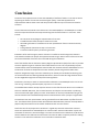
Conclusion ........................................................................................................................................39
Bibliography......................................................................................................................................41
Appendices .......................................................................................................................................43
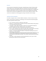
Appendix A. Development of UseCaseExplorer..............................................................................43
System Description ...................................................................................................................44
Use Case Graph Structure..........................................................................................................44
Layout Algorithm.......................................................................................................................45
Controls ....................................................................................................................................46
Attributes of the Graph Nodes ..................................................................................................46
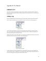
Appendix B. User Manual ..............................................................................................................47
IMPORTANT! .................................................................................................................................47
Adding steps .................................................................................................................................47
Editing Text ...................................................................................................................................48
Adding Alternative Flows ..............................................................................................................49
Connecting Alternative Flows Back to the Parent Flow ..................................................................49
Deleting a Step ..............................................................................................................................50
Include ..........................................................................................................................................50
Extend ..........................................................................................................................................51
Links .............................................................................................................................................51
Loops ............................................................................................................................................52
Scenario Mode ..............................................................................................................................53
Export to RTF Document ...............................................................................................................54
Save/ Open ...................................................................................................................................55
Zoom in/out ..................................................................................................................................55
Assume Steps ................................................................................................................................55
Action Blocks ................................................................................................................................56
Introduction
The technique of use cases for user requirement modeling was devised by Ivar Jacobson in 1986s (3).
By the mid 1990s, use case modeling was recognized as a technique and part of the Unified Modeling
Language (UML) specification supervised by OMG (Object Management Group) (3). The motivation
behind the idea of use cases was to capture the functional requirements of a system. Use cases have
been widely used with different approaches of software development. It is a very useful and lightweight technique to acquire the functional requirements of the system and to model the design
based on those.
A use case is a description of a set of actions that a system performs and it generates an observable
result of value to an actor. It clarifies what the system is supposed to do. The use case diagramming
technique allows a developer to start specifying the system requirements at a high level. It will also
help in presenting these requirements back to the users of the system.
A use case clearly describes how a specific user action initiates a named process to deliver a specific
outcome to the user. Correctly specified use cases provide a direct link to help users and developers
develop a common understanding of the user requirements for a system. They are a proven and
powerful software development tool (4).
The most important part of a use case is the flow of events which describes the interaction
between the system and actor and their behavior in a sequence of steps. There can be
numerous alternative ways in which a use case can unfold depending on particular
conditions. Hence there are a number of alternative paths within the flow of events.
Moreover, flows of events in different use cases can be linked to each other through include
and extend relationships.
Problem
Use cases are specified in the UML specification (3). However, that specification is not very detailed
and leaves a lot up to the user in terms of what information to include and how to structure that
information. Consequently, there are many different approaches, recommendations and templates
for specifying a use case. When it comes to the flow of events there is a vast difference in the
formality between different approaches but in general most approaches are quite flexible and
informal.
There are risks and problems associated with both having too much formality as well as too little. If
too much formality is introduced the use case approach will be harder to learn and might require
more effort. More importantly, it will also be harder for stakeholders in the project to understand
the use cases. A very informal approach on the other hand creates other problems. With little
structure and guidelines the use cases can be harder to read because the information is disorganized.
Moreover, in this case use cases written by different people are likely to be quite different from each
1
other. The quality of the use cases will be a lot up to the writer of the use case. Consequently there is
a need for an approach that achieves a good balance between simplicity, flexibility and structure.
Apart from the issues with structure, the way use cases are traditionally documented in a word
processor also introduces problems. Since the flow of events contain a possibly large number of
different paths it can be hard to read, comprehend and get an overview. This is especially true when
there are a lot of include and extend relationships that further add to the complexity.
Aim
The work described in this report is focused on improving the flow of events of a use case by making
it easier to comprehend as well as supporting high quality writing of event flows. The aim is to
construct a tool that achieves this. In particular the tool should deal with the problem of readability
when a use case is complex and contains several include and extend relationships and numerous
alternative flows. It should also address the lack of structure in the flow of events.
To achieve this, the tool should build on the idea of action blocks (1) to introduce more structure into
use cases. Furthermore, a better graphical representation of the main flow, alternative flows and
exceptional paths in the flow of events should be developed. An efficient way to construct and
visualize scenarios is also a part of the aim.
Demarcations
As stated above the focus of the work in this report is on the flow of events. That is seen as the most
important part of a use case. Thus other parts of a use case like pre- and post-conditions, goal etc.
will not be considered.
When it comes to the flow of events the focus will be limited to readability, navigability and
supporting high quality writing. The work on the flow of events is limited to the structure and
presentation of the flow of events, hence the formulation of the text in the flow will not be
considered.
Structure of the report
This report starts with a background section which describes use cases more in detail as well as the
concept of action blocks. A section describing the method used in this thesis work then follows
together with an analysis section where issues with use cases are analyzed. After that the results
section presents the tool that was developed together with results from evaluations of the tool. The
report ends with a discussion of the performed work, results and conclusions.
2
Background
Use Cases
Use case is a technique used for capturing the system functionality during the analysis phase in a
software development process. They are widely used in software industry for modeling functional
requirements in a manageable format. It is an easy and flexible approach for stakeholders to get an
understanding of the system. Use cases specify the system functionally by representing it in the form
of a flow of events.
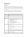
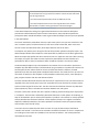
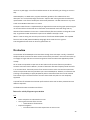
A use case consists of one or many system actors performing a series of actions to achieve a
particular goal. The following example in Figure 1 shows an actor’s interaction with an ATM
(Automatic teller machine) system to perform the system operation “withdraw cash” (1).
Name
Withdraw Cash
Description
Precondition
This use case describes the steps needed for cash withdrawal from an ATM
system.
The connection between ATM system and bank is up.
Input
User inserts cards to withdraw money.
Main Flow
1. User inserts cards to withdraw money.
2. System reads the bank id and account number from the card, validate
3.
4.
5.
6.
7.
8.
Alternative flow
them and prompts user to enter password.
User enters password.
System validates the password.
Use enters the amount of money to withdraw.
System validates the account balance.
System subtracts the amount from the original account balance.
System dispenses card and cash.
2a. Card is not a valid bank card or a destroyed one. Skip step 2 to 8 and
return back to step 1.
4a. Wrong password less than three times. System increments the number of
wrong attempts. Return back to step 3.
4a. Wrong password attempts more than three times. Skip step 4 to 8 and
keep customers card.
Exceptions
6a. Not enough account balance. System prompts user that account does not
have enough money. The total balance remains the same. System dispenses card.
ATM looses network connectivity with bank.
Output
Electrical power failure at any stage.
User gets the required amount of money.
3
Post Condition
If user entered valid password and requested amount was less then or equal to
the total balance then user got the amount and this amount has been subtracted
from the original balance.
If user entered invalid password three times the ATM kept the card.
If user entered requested amount more then original balance the card was
returned back to customer and original balance remained unchanged.
Figure 1 ”Withdraw Cash” Use Case
In the above example the name gives a general idea about the use case while the description
provides more details about the overall contents. Furthermore, the precondition specifies the
prerequisites which should be fulfilled in order to get the desired output from the system as specified
in the postcondition.
The section that follows precondition concerns input to the system. This input can come from a real
user or another system. The flow of events of a use case includes a main flow, which is the main
success scenario and alternative flows, which depict alternate courses of action.
An exception can possibly occur during the life time of a particular operation. Exception steps in the
above example indicate those exceptions so that precautionary measures can be taken against them.
While the output step specifies the value returned to user as a response to the input. After returning
the output, the system also makes sure that a particular postcondition has been satisfied. This
postcondition refers to those circumstances which should be true after a use case has ended.
The above example depicts only one template for the contents of a use case while in practice this
template may take different shapes. The idea behind using a template is to provide more structure to
the description and to make it easier for the user to follow the contents. However, the UML
specification (3) does not specify what a template should look like. This means that it is up to the use
case author to specify his own template. Usually templates include name, actors, short description,
goal, pre/post condition and main and alternative flows.
The main and alternative flows form the flow of events for a particular use case. This flow of events is
regarded as the most critical part of a use case. It specifies the course of action for the actor and the
system to meet the goal of the use case. This does not mean that the flow of events only deals with
system operations, rather it includes the interaction between user and system.
The main or basic flow is written first with a specific numbering scheme showing all the steps placed
in a sequence. The main flow is followed by alternative flows with a similar pattern of numbering. A
step can be detailed or just an outline of the operation it performs. The contents are clearly specified
with an identified start and end of the flow. A clear sequence of steps in this regard is considered
helpful for readability. Moreover, the events specified in the flow are within the system boundary
and irrelevant events are left out (5).
A use case can have relationship with other use cases. The type of relationship is identified as
"include" and "extend". A use case can be included in the details of another use case. In simple terms
an including use case invokes an included use case and uses its behavior. This concept promotes
reuse between use cases.
4
The other relationship between use cases is "extend". It is a bit different from "include" as it includes
a condition. When the condition is fulfilled in the use case being extended the extending use case
enhances the functionality of extended use case. The particular condition is recognized as an
extension point. So extending use case adds to the behavior of an extended use case at an extension
point. The motivation behind this concept is to minimize the code duplication and support reuse.
Action Blocks
Action blocks were originated by Rogardt Heldal (1). The concept advocates that there is a certain
representation flaw in general use case modeling approaches, as these do not efficiently structure
the information. A solution in this regard is to use action blocks to structure the flow of events. It is
an attempt to make use cases easier to read and support authors to write higher quality use cases.
The idea of action blocks is not an exotic concept. It is a structured way of writing the flow of events.
A previously recognized step is named as action step in this world of Action blocks. While, an action
block is a set of action steps of the following types:
1.
2.
3.
4.
Input
Validation
System responsibility
Output
An input step is recognized as an input to the system from an actor. While a validation step specifies
how the input should be verified before proceeding further. If the input is valid, the system performs
its responsibility. Responsibility can be manipulation on data, calculations or storing of data. After
the system performs its responsibility the output is returned to the actor. These steps form an action
block and many action blocks construct a use case.
An action block can consist of any subset of the above step types but they should be ordered as
above. This division of the flow of events into separate action blocks promises to introduce better
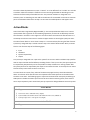
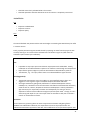
structure to use cases. The following Figure 2 represents the action block concept by considering an
ATM system. It divides the whole system into three action blocks containing three, three and four
action steps respectively. Each action block portrays a particular dialogue between actor and system.
Action Block 1
Action Steps:
1. User inserts cards to withdraw money. (Input)
2. System validates the bank id and account number from the card. (Validation)
3. System prompts user to enter password. (Output)
Action Block 2
Action Steps:
5
1.
User enters password. (Input)
2.
System validates the password. (Validation)
3.
System prompts user to enter amount to withdraw. (Output)
Action Block 3
Action Steps:
1.
Use enters the amount of money to withdraw. (Input)
2.
System validates the account balance. (Validation)
3. System subtracts the amount from the original account balance. (System
Responsibility)
4.
System dispenses card and cash. (Output)
Figure 2 Use Case with Action Blocks
6
Method
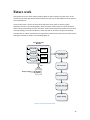
To achieve the goal stated in section Aim, a method was followed to develop and evaluate the thesis
work empirically and experimentally. To construct and evaluate the work and to get more accurate
results, the following set of steps were followed.
•
•
•
•
•
•
Study of books and research articles regarding use case problems
Data acquisition from Interviews with industry personnel
Weekly meeting with supervisor
Analysis of the findings
Design and implementation
Evaluation and review
These steps comprise the method used in this thesis. They are interlinked as the result of each step
satisfies the sequential approach to reach the project goal. Hence, these steps ensure the
implementation of the approach to compile the results near to the project aim.
More descriptively, the work started with a literature study with the aim of getting insight into the
subject and to learn about different problems in handling use cases. Many research articles and
books have been explored in order to get a solid knowledge to base improvement ideas on. Apart
from the literature study, weekly discussions have been held with supervisor Rogardt Heldal.
The result of the literature study and the discussions were a number of ideas about how to improve
use cases and the flow of events in particular. To get some feedback on our ideas and learn about
how use cases are used in industry, interviews were conducted.
Two interviews were performed at Ericsson, one at Saab Microwave Systems and one at another big
IT company that wishes to remain anonymous. The interviews included questions about how use
cases are used in each organization and the interviewees' view on the main strengths and problems
with use cases. Furthermore, the interviewees were asked about what tool support would be useful
for them when it comes to use cases. After that an initial prototype was presented to them and the
ideas for further development were explained. They were then asked to provide feedback and
suggest improvements.
The results from the interviews were analyzed and very much considered in the continued
development of the tool. Several features suggested by the interview subjects have been included in
the final prototype.
Apart from industry feedback the tool has been presented to two researchers at Chalmers who have
given their thoughts on the tool and the underlying ideas. This has also been considered in the
development. Moreover, two of the main commercial use case tools have been studied to find
functions and solutions that could be built on and improved.
At this stage a tool was implemented to realize the ideas resulting from the literature study and the
interviews. The prototype tool was validated in three different ways.
7
Initially the tool was evaluated by inserting sample use cases into the tool. This was done to see if the
use cases could fit in to the structure and format used in the tool as well as to evaluate the different
implemented features.
Secondly, the tool was presented to four engineers at Saab, Ericsson and a third company. The
functionality of the tool was explained together with the rationale behind the features. After that the
engineers were asked to provide feedback on the different features.
Finally, an evaluation was performed with the help of a quality assurance engineer at a big software
company. He was guided through the different features of the tool and then handed a copy of it
together with a short user manual. He used it to input some use cases from a project that he was
currently working on and provided feedback on his test of the tool.
8
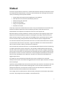
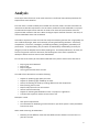
Analysis
The analysis section focuses on some areas and issues in the flow of events where possibilities for
improvements were identified.
First of all there is a need to identify the intended users and their needs. Use cases most often use
natural text to describe requirements. This can make it possible for all the stakeholders in a project
to understand the requirements and thus use cases act as means of communication within the
project and with customers and users. When working to improve the flow of events in use cases, all
of these stakeholders have to be considered.
To be able to improve use cases one must first clarify what makes a good use case. A high quality use
case is defined by Denger, Paech and Freimut (6) as having the following attributes: "consistency,
completeness, correctness, unambiguity, verifiability (testability), changeability, traceability and
prioritization... comprehensibility (easy to read for all stakeholders) and feasibility (necessary for
designers) as well as adequate level of detail (avoiding over- and underspecification)". Of these, the
first four are general criteria for documents, the following four stress what is important for
developers and the last three concern other stakeholders.
For use cases to be used by all of the above stakeholders they have to have an event flow that is:
•
•
•
•
Easy to grasp and understand
Easy to read
Easy to navigate
Gives a good overview of the use case
The needs of use case authors include the following:
•
•
•
•
•
•
•
•
Support for producing high quality use cases.
Support for producing high readability use cases.
Controls for building use cases by including different use case components.
Ease of writing the use cases.
Paper friendly format for use case reviews.
Version control functionality
Support for achieving standardized use cases in a project or organization.
A solution that is quick for authors to learn how to use
Developers' needs:
•
•
Clear precise requirements
The information for developing a certain function or part of the system is easily extractable
from the use cases.
Other needs concerning all stakeholders:
•
Possibility to have different views that show different levels of detail in the use case or in
parts of a use case.
9
Moreover, for a solution to be effective and attractive for companies to use has to be resource
efficient. Therefore the new representation of a use case should be constructed with little or no extra
effort from the author. During the interviews, it was clear that the interviewees were open to an
alternative representation of use cases but only if it was complemented with the traditional use case
view. A reason mentioned for needing the traditional view is that it is more paper-friendly which is
needed for handouts and reviews. Consequently the solution developed in this thesis needs to
include the traditional representation along with any new representation or visualization of use
cases.
To improve and support the use case approach so that it better meets the needs identified above, a
number of different issues were analyzed. The rest of this section describes that analysis in detail.
Navigation and overview
The flow of events of a use case can often be long and complicated with many alternative and
exceptional paths. The flow of events is usually written with numbered steps starting with the main
flow. After the main flow the alternative flows are written. Where each one of those can have its
own alternatives which will follow the parent alternative in the document. The alternatives will have
a reference to the number of the step that they are associated with.
The problem with this representation can be that it is hard to get an overview of the use case. When
reading the main flow there is no indication of where there are alternative paths and the conditions
for those. Therefore the reader needs to read through the alternative flows and see where they fit
into the main flow. One problem here is that in most cases, the alternative flow will be on a different
page than the parent flow and the reader hence needs to flip back and forth between the pages to
understand the behavior described by the use case. This makes it harder to understand the different
paths that exist in a use case and decreases overall readability.
The same problem that is described above is even worse in the case of include and extend
relationships in use cases. An included use case is described in a separate document from the use
case where it is included. This means that to understand the behavior of the paths of a use case the
reader has to switch back and forth between different documents. To improve the readability the
information in the flow of events has to be organized in a different way.
The problem of the extend and include relationships were confirmed during the interviews. The
interviewees described the problems with using these concepts and were instead trying to replace
the use of these with duplicating text in different use cases. The mentioned reason for this was that it
was problematic to have the requirements in different documents when reading it. Moreover, it was
easy to introduce errors when changing an extend use case or an included use case when it was
referenced by several different use cases. Although, the changes may be compatible with one of the
use cases that reference the changed use case, they might introduce errors in others.
Several authors (7) (8) point to the fact that it is hard to get an overview of a use case. To solve this
problem, the use of activity diagrams is suggested (8). Automatic generation of activity diagrams (10)
is a feature included in two commercial use case tools, Case Complete (11) and Visual Use Case (12).
10
Activity diagrams show the paths through the use case and provide an overview that the traditional
use case representation lacks. The information is also organized in a way so that there is less need for
switching between different parts of the document when reading, e.g. to look up an alternative flow.
The benefits of the activity diagram view were the reason why this representation was chosen as a
starting point for the work on an improved representation in this thesis.
A problem with activity diagrams is that they can get very big and incomprehensible when use cases
are complex and contain many steps. In this case it can be hard to follow the paths through the use
case, especially if the steps contain a lot of text, since the activity diagram will then be very cluttered.
This is something that a solution based on activity diagrams have to address.
Another possibility to improve the flow of events is by introducing more structure into it in order to
support the author in producing high quality use cases.
Supporting writing of the flow of events
When it comes to writing, the informal nature of use cases can cause problems. The lack of structure
and rules for writing use cases leaves it a lot up to the writer to produce high quality use cases. This
has been recognized by several authors (8) (6) (13) who present a wealth of guidelines for writing
effective use cases. These are however, mostly focused on the actual text within the use cases but
not on the structure and presentation of the flow of events, which is the focus of this report.
There are many possible ways to introduce more formality in the flow of events. There are several
ideas from different researchers that try to address this (see Related Work). An example of such an
idea involves adding an underlying layer to a use case that adds formality to it (14). A problem with
many of these ideas is that they interfere with some of the strengths of use cases namely flexibility
and readability. If more formality is going to be added it should be done in a way that as much as
possible limits negative impact on simplicity, flexibility and understandability.
During the interviews that were performed as a part of this thesis, several of the interviewees used a
form of structure that was similar to action blocks with a division into different types of steps. The
step types and structure were however different from action blocks and were also different between
the interviewees. This suggests that introducing structure in the way action blocks do, can be an
effective solution.
One of the ideas behind action blocks is that by introducing some more structure into the use case
flow, writers will be able to produce use cases of higher quality. Heldal and Staron (15) have done an
experiment that points to action blocks as being effective in improving use case quality. Based on this
the action block idea was chosen as a starting point for the work on supporting event flow writing in
this thesis.
Increased structure in the flow of events could also be part of a solution to a problem that was
voiced during the industry interviews. That problem is that use cases produced in a project are not
standardized. Interviewees responded that they had guidelines for use case writing to achieve
standardized and similar-style use cases. However, these guidelines were only partly effective. The
11
chances of achieving good standardization can be increased by having more structure in the flow of
events.
Another way to support writing of use cases is by analyzing the text that the use case author is
writing. By using language analysis it can be judged if the use case is likely to be of good quality. The
author could then be prompted for tips on how to change his or her writing style to improve quality.
Work towards achieving such functionality is presented in the article Supporting Use-Case Reviews
(16). However, there is much work left in this area before the functionality described above could be
implemented. Therefore, this path was not pursued in this thesis.
A further aspect of writing and changing use cases is avoiding errors, for example referencing the
wrong step of the parent flow in an alternative or making a mistake in the numbering of a step. By
using a tool where use cases are constructed by using functions for inserting the different elements
into use cases the risk of such errors should be reduced.
Implicit assumptions in the flow of events
Increasing the structure of a use case can help to make it clearer. Another issue of insufficient clarity
in use cases is implicit assumptions in the flow of events.
The main flow or the main success scenario is supposed to represent the behavior of a system in the
"normal" case or in the case of no errors. In the book Use Case Modeling (6) the main flow is defined
as "the normal, expected path through the use case" and Writing Effective Use Cases (13) uses the
definition "a case in which nothing goes wrong". These definitions are very imprecise and it can be
very hard for someone to know what assumptions are made when continuing to the next step in the
main flow. Lets take a local taxi service in Gothenburg as an example. A part of the event flow of a
use case for such a service can look like this:
Main flow:
1.
2.
3.
4.
5.
Customer enters the taxi and tells the driver the address that he or she wants to go to
Driver confirms address and drives the customer to the desired destination
Driver asks customer for payment
Customer pays for the trip
Driver hands the customer a receipt
Alternative flows:
2a. Address is not in Gothenburg
1. Driver informs customer that the taxi service is only for addresses within
Gothenburg.
In the use case above the reader of the use case will be unaware of the restrictions on where the taxi
service operates after reading the main flow. It is not until reading the alternative flows that this
becomes clear. There is nothing in the main flow that indicates to the reader that an assumption is
12
made at step 2 in the use case. To know this the user has to read the alternative flows. It might
therefore be beneficial to indicate where assumptions are made in the main flow, i.e. where there
are alternatives, to give the reader a better understanding of the main flow. Also what the "main
scenario" or "main success scenario" means can be clarified by explicitly stating the assumption that
is made when continuing down the main flow.
The validate step in action blocks does help to point out places at which the execution path of the
use case is dependent on a particular input. However, it does not necessarily specify the condition or
assumption on the input that is made when continuing down the main flow. This shows a need for a
mechanism that makes these implicit assumptions clearer and also clarifies the meaning of the main
success scenario.
Syntax and semantics of referencing alternative flows
When it comes to clarity in use cases a further topic of importance is the syntax and semantics of
referencing alternative flows.
The flow of events can contain a large number of paths through it. This is achieved by alternative
flows whose executions depend on some condition at a certain position in a parent flow. One issue
with alternative flows is the syntax and semantics of how they refer to a particular step in the parent
flow. The way that this referencing is done can affect the readability of the use case.
There are numerous different ways to reference used by different authors. Two common ways to
reference are by using the number of the step in the parent flow and by including labels in the parent
flow.
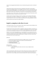
The problem with the labels approach can be seen in Figure 3 (6) below is that if there is a need for
many labels in the parent flow that can cause it to be cluttered and less readable. The benefit is that
if a label has a descriptive name, then it becomes easier to know where in the parent flow an
alternative is referring without actually having to look in the parent flow.
----
Basic flow:
{Insert Card}
1. The use case begins when the actor Customer inserts a bank card into the card reader
on the ATM.
2. The system allocates an ATM session identifier to enable errors to be tracked and
synchronized between the ATM and the Bank System.
13
{Read Card}
3. The system reads the bank card information from the card.
{Authenticate Customer}
4. Include use case Authenticate Customer to authenticate the use of the bank card by the
individual using the machine.
{Select Withdrawal}
5. The system displays the different service options that are currently available on the
machine.
6. The Customer selects to withdraw cash.
{Select Amount}
...
Alternative flows:
...
5.1.1 Handle the Withdrawal of a Non-Standard Amount
At {Select Amount} if the Customer requires a non-standard amount,
1. The system asks the Customer for the required amount indicating that the
amount entered must be a multiple of the smallest denomination note held and
must be below the amount of the ATM's withdrawal limit and the amount of
currency held by the machine.
2. The Customer enters the desired amount.
3. Resume the basic flow at {Confirm Withdrawal}.
...
---Figure 3 Problem with Labels Approach
The other approach, that references the parent flow by step type, does not have the problem with
cluttering. However this makes it a lot harder to know by heart where in the parent flow that the
alternative refers to and there is therefore an increased need to search back and forth in the
document.
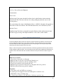
There are also examples of less structured ways of writing the alternatives like Figure 4 (17) below. In
this case the alternative does not have an exact reference to where in the main flow it fits in. This is
instead described in the text in the alternative which is a much less exact way of referencing than the
two referencing techniques described above. For this simple use case the imprecise referencing still
works fairly well but for more complex use cases it would cause readability problems and unclear
requirements.
14
--Use Case - Process Received Shipment
Documentation:
Basic Course
The Receiving Clerk ensures that the Line Items listed on the Purchase Order match the
physical items. The Clerk waves the bar code on the packing slip under the sensor at the
receiving station.
The system changes the status of the Purchase Order to “fulfilled” and updates the quantity on
hand values for the various Books. The Clerk hands the Books off to the Inventory Clerk.
Alternate Course
If the Receiving Clerk finds a mismatch between the Purchase Order and the physical items,
the Clerk stops processing of the shipment until he or she is able to make a match.
--Figure 4
Example of Less Structured Use Case
The activity diagram solution does not require this type of referencing. However, the use case tool
should support the traditional use case view as well and in that view referencing will be needed.
Since the traditional view is auto-generated from the activity diagram view only the step number
referencing can be done without extra user input.
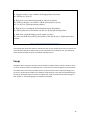
When it comes to the precise syntax and semantics of referencing alternative flows by step numbers
it differs between different authors. The technique that was found most readable was preceding the
condition of the alternative flow with a number reference to the parent flow as shown in Figure 5
(13).
--Main success scenario:
1. User selects to buy stocks over the web.
2. PAF gets name of web site to use (E*Trade, Schwabb, etc.)
3. PAF opens web connection to the site, retaining control.
4. User browses and buys stock from the web site.
5. PAF intercepts responses from the web site, and updates the user's portfolio.
6. PAF shows the user the new portfolio standing.
Extensions:
2a. User wants a web site PAF does not support:
2a1. System gets new suggestion from user, with option to cancel use case.
3a. Web failure of any sort during setup:
3a1. System reports failure to user with advice, backs up to previous step.
15
3a2. User either backs out of this use case, or tries again.
4a. Computer crashes or gets switched off during purchase transaction:
4a1. (What do we do here?)
4b. Web site does not acknowledge purchase, but puts it on delay:
4b1. PAF logs the delay, sets a timer to ask the user about the outcome.
4b2. (see use case Update questioned purchase)
5a. Web site does not return the needed information from the purchase:
5a1. PAF logs the lack of information, has the user Update questioned purchase.
5b. Disk crash or disk full during portfolio update operation:
5b1. On restart, PAF detects the log inconsistency, and asks the user to Update questioned
purchase.
--Figure 5 A Better Approach to Specify Alternative Flow
This example also shows the semantics that were chosen for the numbering scheme in this thesis. 4a
means that this alternative replaces step 4 in the main flow if the condition is true. The alternative
would be that 4a follows step 4 if the condition evaluates to true.
Loops
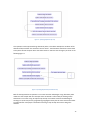
Sometimes when writing use cases there arises a need to repeat a section a certain number of times
or until a condition is false. An example of this is in the case of a check out registry at a supermarket.
The cashier will use the same procedure to enter all the customer's items. One way of doing this in
use cases is by writing the condition for repetition inside the flow. In this case the step following the
last step of entering an item will contain a condition like "while the customer has more items go to
step number X". The following Figure 6 illustrates this example.
16
Figure 6 Specifying Repetition by Loop
This repetition can be expressed using alternative paths. In the above example the condition of the
alternative flow would be "the customer has more items". The alternative would then connect back
to the parent flow at the point where the cashier enters a new item into the registry as shown in the
following Figure 7.
Figure 7 Specifying Repetition by Alternative Step
Both of these approaches to repetition in use cases have their advantages. Using alternative paths
makes use cases simpler with less concepts and it constitutes a uniform way of handling control
statements in use cases. Using an explicit loop concept on the other hand has the advantage of
working in a similar way to many programming languages and may thus be more intuitive and easier
to understand for most people. The benefits of having a loop concept were seen to weigh the
heaviest.
17
Different views with different levels of detail
Use cases written for complex system can be long in nature. Since there is no industry standard for
use case length and degree of detail those can vary a lot between use cases. A use case's main aim is
to provide the details without the reader getting lost and loosing focus. So while designing a use case
one should make sure that even long use cases can be read easily and the reader comprehends what
the use case is attempting to describe (8). A way to alleviate this problem can be to provide
functionality to hide and show different information/details. This can help the reader to comprehend
the big picture of the use case while still having a complete specification (8).
The above reasoning was confirmed during the industry interviews, where a need for the tool to
provide several views, showing different levels of detail of the use case was expressed repeatedly.
Such a function can enhance communication by adjusting the level of detail depending on the
purpose for which the use case is viewed. It should also be possible to show the details of a part of
the use case while the rest is shown at a high level. In that way the readers get the context of what
they want to study in a good way.
Scenarios
Apart from increasing readability and structure in use cases another aim of this thesis work was to
provide a quick and convenient way to visualize scenarios through a use case. The need for
constructing scenarios was confirmed by the interviews that were conducted. The interviewees
expressed a need to have scenarios as a base for verifying and reviewing use cases as well as to gain
in-depth understanding of them.
The problem of creating scenarios in use cases has been addressed by Heldal, Samuelson and Sundin
(18) who present a tool for exploring scenarios through a use case. However, that tool requires extra
effort from the use case author to enter the use cases into the tool. This reduces the usefulness of
the tool and the tool produced in this thesis should aim to minimize the effort needed to construct
scenarios.
Links
Use cases can be a base for many other artifacts e.g. software requirements specification, test cases,
sequence diagrams, class diagrams and state charts. Consistency and traceability between a use case
and these other document can be controlled by providing a tagging function where tags can be
inserted in the use case with references to other documents. Use cases should potentially be able to
have tagged lines or words for later implementation in other documents. This technique can be very
useful even for the justification of the use case from other documents, increase traceability and
result in a better system-requirements fit.
18
Existing Use Case Tools
Many other commercial software tools which deal with use case creation have been analyzed during
the analysis phase. Of these there are two major tools that are made especially for use cases, Case
Complete (11) and Visual Use Case (12). They both have similar functionality when it comes to the
flow of events. They both include a glossary function with highlighting of glossary terms in the flow of
events. The flow of events in both tools has two representations, the traditional flow of events
representation with a sequence of numbered steps and an activity diagram representation.
The traditional representations include hyperlinks to make it quicker to open included and extending
use cases, however they are still opened in a separate document. Moreover the tools do not address
the problem of having to jump back and forth between pages when reading the use case.
The activity diagram representations in the tools do give an overview of use cases but are not well
suited for large use cases with a lot of text. The activity diagrams in Visual Use Case are hard to
follow and it is not evident which is the main flow.
Both tools also include a lot of other functionality like requirements tracing, collaboration and
versioning.
19
Results
The analysis part gives an understanding of the problem domain. It depicts the issues while dealing
with use cases and possible solutions. After a detailed analysis of the problem all efforts were put on
developing solutions to these problems. Many ideas, e.g. using action blocks, providing an interactive
activity diagram etc. were considered. These ideas have been discussed with the supervisor, faculty
members and with industry people. The feedback regarding these ideas helped a lot to reach the
results. There have been much brainstorming and modification to the initial concepts in order to
improve on them and achieve a quality outcome. The following section presents the results of that
work including the software tool which includes functionality to support the ideas that were
developed in this thesis.
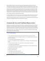
Assume Step in Action Block
The work on structuring the flow of events has resulted in a development and slight amendment of
the concept of action blocks. The idea of action block initially had four basic step types, input,
validation, system responsibility and output. A modification has been made concerning the validation
step as it has been replaced by a step called "assume". The other steps remain unchanged and must
still appear in the mentioned order. However, the assume step can be inserted anywhere in an action
block and does not adhere to any ordering restrictions.
The assume step is a step which specifies assumptions that are made in different places
throughout the flow of events. It can be assumptions on the user input, e.g. that the user has
entered the correct PIN into the system. It can also be an assumptions on the outcome of
system responsibilities, e.g. the system was able to successfully store a file to the hard drive
in a save operation. In this way the assume step can include the information that was
previously in the validation step but the assume step is more flexible.
Moreover, the assume step can help to make the assumptions made in the flow of events
more clear and explicit. It is intended to address the problem of implicit assumptions which
was described in the analysis section. With this in mind, a restriction has been added to the
flow of events. The restriction is that alternative flows can only branch from, or be
connected to, assume steps. The rationale behind this is that if there is an alternative,
different assumptions will lead to different paths through the use case. Thus, an assumption
is made when continuing down the current flow. There is also an assumption associated with
following one of the alternative flows connected to that step. By restricting alternatives to
only be associated with assume steps there will always be an indication that some
assumption is made when continuing down the current flow and not following an
alternative. With assumptions, included in the flows at all branch points, it can be made
clearer what is the actual meaning of the "main success scenario".
The following example, which is based on ATM illustrates the concept of action block in more detail
as it shows an action block with a validation step and later the same action block modified by adding
20
an assume step to it.
The following table in Figure 8 represents the first action block of an ATM.
Action Block 1
Action Steps:
1. User inserts cards to withdraw money. (Input)
2. System validates the bank id and account number from the card. (Validation)
3. System prompts user to enter password. (Output)
Figure 8 Action Block Without Assume Step
The same action block is modified to use an assume step and gets the following shape as shown in
the following Figure 9.
Action Block 1
Action Steps:
1. User inserts cards to withdraw money. (Input)
2. Bank id and account number is valid. (Assume)
3. System prompts user to enter password. (Output)
Figure 9 Action Block With Assume Step
In the above example assume step is a deciding body among the main flow and
alternative flow. An alternative flow to action block 1 can be seen below in Figure 10.
Alternative to Action Block 1
Action Steps:
1. User inserts cards to withdraw money. (Input)
2. Bank id and account number is invalid. (Assume)
3. System prompts user that bank id or account number is invalid. (Output)
Figure 10 Alternative Flow to Action Block 1
The above example indicates that an assume step is nothing but an assumption to follow a particular
course. Consequently, an assume step can be linked to an alternative path. In order to decide
between main and alternative, one need to make an assumption.
21
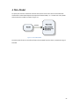
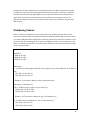
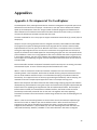
A Meta Model
To specify the structure of the flow of events that was the result of this work a meta model was
constructed. A meta model depicts the properties of actual models, i.e. it contains the rules, details
and constraints on models as shown in Figure 11.
Figure 11 Use of Meta Model
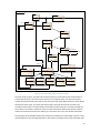
The meta model for the use case flow of events that resulted from this thesis is presented in Figure
12 below.
22
class MetaModel
Includes
+receive
Extends
Actor
UseCase
1
*
1
MainFlow
1
1
Flow
0..*
1
1
Alternativ eFlow
+al ternatives 0..*
has alternatives
*
*
ActionBlock
1
1
+i ncl ude posi tion
+goto
1
ControlSentence
*
*
ActionStep
Loop
-
condition: Stri ng
-
0..1
condi tion: String
+return positi on
text: Stri ng
0..*
1
Input
System Resp.
Output
Unspecified
Assume
+provi des
Figure 12 The meta model for the use case flow of events
The meta model in Figure 12 shows how the flow of events is structured and how action blocks fit
into the flow of events. The flow of events consists of a number of flows, one main flow and any
number of alternative flows. Each flow consists of steps and/or action blocks where the action blocks
themselves contain steps. This means that all the steps in the flow of events do not have to be
included in action blocks. The meta model permits flows of events with all or no steps included into
action blocks. This makes it possible to enter use cases with sections that cannot be easily made to
conform to the action block structure. Mainly, this can be the case in the start of alternative flows.
The step types of the modified action block concept are included in the meta model as well as a step
named unspecified. The rationale behind this is that there can be steps that include information that
23
is not well described by any of the action block step types. What can also be seen in Figure 12 is that
loops are implemented as steps. A loop consists of a step which includes a condition for which to
loop back to a previous step. The reasons for implementing loops in this way were covered in the
analysis section.
A flow represents the body of a use case but there can also be include and extend relationships
among two different use cases. This relationship is catered by include and extend domain objects. An
included use case is attached to a particular step in the event flow. Similarly, an extended use case is
connected to a step in the flow of events. However, extended use cases are connected to assume
steps through a control sentence.
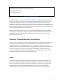
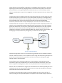
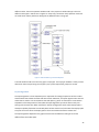
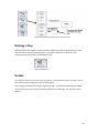
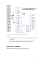
Interactive Activity Diagram (IAD) Representation
The results presented so far have mainly considered the structure of use cases. The work in this
thesis has also involved the representation of use cases and the most important result in this regard
is an interactive activity diagram (IAD) representation of the flow of events.
The IAD representation is an activity diagram with interactive features that lets the reader
manipulate the view of the use case. The reader can control which information is visible and navigate
through the different paths of the use case using different navigation and zoom controls.
Figure 13 Interactive Activity Diagram View of UseCaseExplorer (overview)
24
Figure 13 shows an overview of a use case entered into UseCaseExplorer which shows it as an
interactive activity diagram. The box surrounding the leftmost flow represents the main flow. There
are conditions to the right of the main flow that are connected to steps within the main flow. These
are the conditions of alternatives connected to those steps. By clicking these conditions the reader
can expand and contract the alternative flows as he or she likes. In this way the information in the
alternative flows is easily available to the reader. Also the IAD is intended to give the reader a clear
overview of the use case and make it easier to see where the alternatives fit in to their parent flows.
This is helped further by the inclusion of zoom controls.
The IAD also addresses the problem with having to switch between different documents when there
are include or extend use cases. In the IAD the include and extend use cases are represented by a
node. By clicking this node the include or extend use case can be expanded into the current use case.
A second click will again contract that use case back into the node.
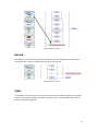
Automatically Generated Traditional Representation
As explained in the analysis section there was a need for a traditional representation of use cases to
accompany a new representation. The way this has been solved is by automatically generating the
traditional representation from the IAD. The IAD contains all the information that is in the traditional
view of the flow of events. Therefore it has been possible to develop an algorithm that achieves this
automatic generation. Figure 14 below shows a part of a use case in the traditional representation
which has been generated from an IAD.
Figure 14 Sample RTF Document Generated by UseCaseExplorer
25
The algorithm has been implemented in UseCaseExplorer where the IAD is represented by a graph.
The algorithm works by traversing the graph flow by flow starting with the main flow. In each flow
the texts are fetched from the nodes together with any alternative flows that are attached to the
nodes. After one flow has finished the alternatives in that flow are processed one by one. The
algorithm also assigns numbers to each node so that the steps can be numbered in the generated
flow of events.
Numbering Scheme
When it comes to the traditional use case representation the numbering scheme of the flow of
events is an important factor for being able to follow the different paths through the use case. There
is no specific UML specification regarding the numbering scheme of the event flow. Instead it is up to
writer to specify the numbering which can lead to an ambiguous scheme. A result of the work in this
thesis is a numbering format which aims at being clear and easy to read. This format takes the shape
shown in Figure 15 below.
Main Flow
1. Main flow step 1
2. Main flow step 2
3. Main flow step 3
...
Alternatives:
1a. Condition for entering this alternative flow (replaces step 1 in the main flow if condition is
true)
1a|1. Step 1 in alt. flow 1a.
1a|2. Step 2 in alt. flow 1a.
...
Return to 3 (execution continues at step 3 in the main flow)
Alternatives to alternative 1a.
1a|2a. Condition (if true: replaces step 2 in flow 1a.)
1a|2a|1. Step 1 in flow 1a|2a.
1a|2a|2. Step 2 in flow 1a|2a.
...
Return to 1a|5 (execution continues at step 5 in alternative 1a)
1b. Condition (Second alternative to step 1 in the main flow.)
1b|1. Step 1 in alt. flow 1b.
1b|2. Step 2 in alt. flow 1b.
...
26
2a. Condition (if true: replaces step 2 in main flow)
2a|1. Step 1 in flow 2a.
2a|2. Step 2 in flow 2a.
...
Figure 15 A Better Numbering Scheme
The steps numbered 1, 2, 3 and so on make up the main flow. The alternative flows are specified
after the main flow in the document. The numbering of the alternative flows includes a reference to
the step which they are connected to in the parent flow. Alternative "1a" represents the first
alternative to the first step of the main flow where "1" indicates the step and "a" indicates that it is
alternative "a" of that step. In the same way alternative "1b" represents the second alternative of the
same step. Alternative flows can themselves have alternatives and alternative "1a|2a" indicates the
first alternative to the second step of alternative "1a".
The step to which an alternative refers to is the step that will be replaced by the first step of the
alternative if the condition is true. Where to continue the execution after the end of an alternative is
specified by a "return to" statement which indicates the return step. If there is no "return to"
statement the use case ends.
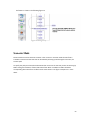
Scenario Visualization and Construction
One of the main aims of this thesis was to provide a way of constructing and visualizing scenarios in
use cases. This has been done by utilizing the IAD representation. UseCaseExplorer includes a
scenario mode and when that mode is active the user can construct scenarios by clicking the
conditions that are true in the intended scenario. The rightmost flow, which normally represents the
main flow, represents the scenario in scenario mode. Therefore when clicking a condition the
alternative associated with that condition is shifted into/included in the scenario. This can enable
quick construction of scenarios which are visualized by an IAD.
Links
To support traceability of requirement was one of the requirements that were identified in the
analysis. This has been addressed by introducing the possibility to add links to action steps. These
links are comprised of a description and a path to a particular file or document. In this way other
requirements documents can be referenced. Moreover, this function can be used to attach
documents that can include details of and further specify the requirements in a particular step.
27
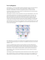
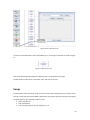
UseCaseExplorer
UseCaseExplorer is a Java based standalone application designed to support the concepts that have
been presented above, e.g. action blocks, and to provide the better readability of use case
descriptions. UseCaseExplorer has been built using Prefuse (2) which is an open source data
visualization framework. Prefuse serves as a base for the implementation of the interactive activity
diagram (IAD) representation of use cases.
UseCaseExplorer implements the IAD representation of use cases as described above. The use case is
represented by a graph within use case explorer where the different steps are the nodes in the
graph. Constructing use cases is supported by adding different elements like action steps, action
blocks and include use cases into the current use case. These elements are added by using the
controls in the menu at the left side of the screen as seen in Figure 16. Moreover, the controls also
include a button for entering the scenario mode which works as described above. The controls are
implemented with the help of the observer design pattern. Events are generated when the user clicks
items in the view and those events are propagated to the controls which respond dependent on the
current mode of the program.
Figure 16 Controls in UseCaseExplorer
After adding steps to a use case they can be edited using an integrated text editor which also lets the
user select the appropriate step type. This text editor is an adaptation of the open source text editor
TextEditor++ (19).
The user can navigate through a particular use case by viewing its main flow and following the
alternative flows. The alternative flows are hidden initially to provide the main success scenario of
the use case. An alternative attached to an action step can be reached by pressing the condition of
that alternative. Arrows are present to indicate the flow in a precise way which can prevent user
from loosing focus. When contracting and expanding steps the transitions between the different
states are animated.
UseCaseExplorer supports linking documents to action steps with the link control shown in Figure 16
above. Linked documents are stored in UseCaseExplorer as a description of the link together with a
relative file path to the file from the use case. A URL can also be attached in similar fashion to get
28
access to any web page. A list of the linked documents can be reached by just clicking on an action
step.
UseCaseExplorer, as stated earlier, supports automatic generation of a traditional use case
description. This is achieved through the function "export as RTF" which generates the traditional
representation in the form of an RTF (Rich Text Format) document. This RTF document is very much
similar to an MS Word document in its nature.
The export as RTF function is implemented by an algorithm that traverses the graph representing the
use case and collects the text and other information associated with each node along with any
alternative flows attached. The use case is traversed flow by flow and numbers are assigned to each
step. To generate the RTF document the open source software iText (20) is used.
When it comes to saving use cases they are stored in a file format called GraphML. The GraphML
format is built on XML (eXtensible Markup Language) which means that it is a generic
interchangeable format which can be easily opened later on.
Evaluation
The evaluation of UseCaseExplorer has been done through three techniques. Initially, a handful of
sample text book use cases have been written into the tool by the authors. These use cases were up
to 14 pages in length and were structured using action blocks to evaluate the applicability of that
concept.
All use cases were possible to input into the tool and most of the event flows were possible to
structure with action blocks. However, the start of alternative flow was frequently found hard to fit
in to an action block. The overall picture of use cases was seen as more clear and the content was
easier to comprehend when they had been input into UseCaseExplorer. However, one function that
is lacking is the possibility to specify exceptional paths or alternative flows which can be reached
from several steps in the flow of events. Use cases that include such paths are not completely
supported.
A second form of evaluation that has been performed is that the tool has been presented at three
different companies.
The feedback that was received was as follows:
Interactive activity diagram representation
Pros
•
•
•
Easier and quicker to understand a use case
Gives a good overview of the use case
o Good indication of alternatives
Improved navigation
o Include and extend use cases expand into current use case
29
•
•
•
•
•
Improves standardization within a project/company
Easier to make changes to use cases
Reduced risk of mistakes when writing use cases
Supports linking
o Good for including diagrams
o Good for referring to special requirements
Faster to construct use cases
Cons
•
•
•
•
•
An alternative flow that, depending on certain conditions, returns to different places in the
parent flow is not supported.
Linking function could be improved
o Could be better visualized
o Could be more flexible
o Could include user defined tags, e.g. differently colored tags
Should include a communication view showing communication between actors and system
Lack of synchronization concept
No support for versioning
Automatic Generation of Traditional Representation
Pros
•
•
•
Gives support for handouts
Needed for reviews
Numbering scheme quite clear
Cons
•
•
•
Main flow should indicate where there are alternatives
Links specified in the IAD should be included
The layout and structure of the generated document could be improved
Scenario Mode
Pros
•
•
•
Good for quickly creating scenarios for testing
Good for showing customer
Good for reviews
Cons
30
•
•
Should be more clearly indicated what is the scenario
Should be possible to hide the alternatives once the scenario is completely constructed
Action Blocks
Pros
•
•
•
Improves standardization
Improves structure
Improves quality
Cons
•
The overall feedback was positive and the tool was thought as something that would clearly be useful
in a mature version.
Finally, a quality assurance engineer tested the tool by inputting use cases from the project he was
currently working on. The results of this evaluation were as follows in Figure 17 (taken from the
evaluation report written by the evaluator).
-----
Pros:
•
•
•
It provides an easy way to present and discuss requirements with stakeholders. Usually,
traditional use case documentation requires a lot of effort to read through and comprehend.
Export feature gives an edge to synchronize with traditional documentation practices.
The notations, e.g. ‘I’ for input, make it easier to understand different types of action.
Cons (Suggestions):
•
•
The possible improvement area is the usability or more specifically ease to learn. One
suggestion in this regard is to get it somewhat compliant with other UML tools.
Since agile methods are getting wide proliferation in software development industry
nowadays. So, it would be nice to introduce some new features to facilitate that community
needs as well. For instance, Acceptance Test Driven Development is warmly embraced in
agile community for requirement elicitation and subsequently for testing. A little bit
expansion of the tool will be sufficient enough to cope with these needs. Though, it’s not a
shortcoming and maybe it’s not in the scope of the current effort as well, but it could be a
note for an enhancement in future.
Conclusion:
The tool seems very promising when we come to requirement elicitation and getting further
feedback from stakeholders. Moreover, the export feature let us to stay compliant with our
traditional documentation approach as well. But, little modifications to incorporate Acceptance TDD
31
will make it a perfect choice for us.
--Figure 17 Evaluation Report of UseCaseExplorer
32
Discussion
Thorough system testing and evaluation is highly encouraged to deliver efficient, high quality
software. This also decides the future success of software. UseCaseExplorer has gone through some
testing and evaluation in this sense as described above. For example, a handful of use case experts
have evaluated the software with positive feedback. However, more evaluation can be made to
further verify the concepts and ideas in this report and make them more mature. More research in
the form of quantitative and qualitative studies can make the applicability and usefulness of the
results of this thesis clearer.
The evaluation phase pointed out some things that can be improved in the present version of the
UseCaseExplorer. One such shortcoming concerns alternative flows (or exceptions) that can be
reached from several different places in the flow of events. The way UseCaseExplorer is currently
implemented such an alternative flow has to be duplicated at all the steps from where it can be
reached. This negatively impacts the usability of UseCaseExplorer on use cases of that type.
Another left out feature is related to an alternative flow which returns to different places in the
parent flow depending on a particular condition. An example of this is an alternative that returns to
step number 15 in the parent flow if a condition is true but if that condition is false it returns to step
number 12. This functionality is not supported in the UseCaseExplorer so a user is a bit restricted
when dealing with the IAD. This restriction can have an influence on usability of the UseCaseExplorer
as all use cases cannot be easily entered. To enter such a use case the two versions of that
alternative have to be entered as two separate alternative flows which causes text duplication.
UseCaseExplorer is certainly equipped with features which facilitate for the user to write and read
use cases. Most of its features are based on research studies conducted in this context while some
originate from feedback from industry. Some of the requirements resulting from the industry
interviews have been left out. One of those is related to the level of details a use case should provide
e.g. a use case description should have many levels of detail based on the current user (i.e. client or
developer) or purpose. In other words, what text is visible in each action step should be possible to
choose depending on the purpose for which the use case is read.
A second issue deals with lacking features in the text editor for formatting text, draw pictures and
including tables. Moreover, as use case can have more than one writer, it can be updated several
times by different people during various phases. Consequently, it can have many versions. A
comparison between two versions can give the added functionality or difference between the
versions. This updated or added description can be needed for reference and versioning control.
Version control is missing in the UseCaseExplorer even though having this functionally can be very
useful and practical.
Considering the absence of the above features it is bit hard to figure out would the tool be successful
and applicable for industrial use although the feedback received has been positive.
The idea of action blocks claims to achieve higher quality use cases than the traditional approach of
use case modeling. The results of an experimental study performed by Heldal (15) show that the
33
overall structure of use cases becomes more readable and that the quality of use cases is improved.
Since the idea of action blocks, as implemented in UseCaseExplorer, has been developed and slightly
changed these results are not directly applicable. However, the main idea for introducing structure
into use cases remains the same so these results still support the structuring as implemented in
UseCaseExplorer.
The graphical interface in UseCaseExplorer is fairly interactive but still there are some usability
concerns like no popup menus and no multiple selection or dragging. Also, the technique to write use
case with action blocks is a new idea which demands some time of the user to get used to. These
shortcomings are negative for the tool but overall the interactive activity diagram layout has been
liked by industry professionals.
Several use case modeling software tools generate activity diagrams based on use case descriptions.
These activity diagrams show the flow of events in a non-interactive way. This makes the life hard for
the reader as one lose focus while following through any particular scenario. UseCaseExplorer, on the
other hand, provides a highly interactive way of presenting use case contents. Moreover, it is easy to
follow the flow as user can hide and compress irrelevant details on the fly. This approach seems to be
a considerable improvement over the market available software.
One aim of the project was to provide the good visualization of scenarios. UseCaseExplorer has
adopted an approach to represent scenarios by moving alternative flows into the main flow.
Although this approach points out the possible scenarios to the user, there is still a certain lack of
decent portrayal of them. A user does not get each scenario clearly specified by the tool since all
other alternatives remain visible in the same flow. This is a shortcoming in order to have a good
visualization of scenarios. A better approach in this regard would be to only show scenarios and rest
of the details should be hidden.
34
Future work
During the work on this report a large number of ideas on how to improve use cases arose. In this
section a few of those ideas will be presented where the focus lies on what additions can be made to
the UseCaseExplorer.
As each action block is consists of many action steps these action steps are actually system
operations as shown in the following figure. So by the nature of action steps one should be able to
obtain several system operations from a use case. These system operations provide the base to write
contracts (adding pre and post conditions). These contracts can be written using formal methods.
This approach can lead to automatic test case generation and these test cases can be used for system
testing and validation as shown in the following Figure 18.
Figure 18 Use cases for System Testing
35
Another field in which more efforts can be placed is in language analysis of use cases. In the article
Supporting Use-Case Reviews (16) language analysis is used to assess the quality of use cases and
point out places where it might be possible to improve the use case. Such functionality could be
added to UseCaseExplorer to give the user suggestions on how to improve the use case and point out
mistakes.
A system glossary can be included into the tool so that when writing use cases the author can insert
words from the glossary into the use case. The words included in the glossary can be highlighted in
the flow of events and provide a link to the description of that word. Since common terms will then
be used throughout the use cases they are likely to be more precise and understandable.
Furthermore, a domain model is usually developed prior to use cases. This model is an abstract
conceptualization of real system. It contains the system objects and their relationship to each other.
A glossary can be made based on domain objects and other system entities. If one uses the system
glossary as a reference for use case actors, system objects and operations this can help to improve
quality and consistency between different design documents. Also while writing use cases the
availability of information e.g. actors and domain objects will make the life easier for the analyst. The
following Figure 19 explains how the system glossary is linked to the use case diagram.
UseCase1
Domain
Analysis
Use Case
Notations
System Glossary
UseCase 2
Use Case 3
Use Case Diagram
Figure 19 Use of System Glossay
Graph analysis algorithms can be run on the use case to give statistics such as complexity measures
and total number of scenarios. For less complex use cases it might also be feasible to generate all the
possible scenarios automatically or generate a small amount of scenarios which gives as good
coverage of the use case as possible.
The link function can be improved so that there is a choice whether a linked document will be
included as a hyperlink in exported RTFs or if it should be included into the document. In this way
there is support for including pictures, tables and nicely formatted text into exported documents.
Different views can be added to the program that show different levels of detail depending on who is
reading the use case and in what purpose. Different views can show and hide different information
within each action step and within action blocks.
The program can be extended to support constructing complete use cases, not just the flow of
events, according to a user specified template. The template can also include company specific use
36
case writing guidelines that the user is reminded of when writing a use case. It might be possible to
merge the open source project "Use Case Maker" (21) with the UseCaseExplorer to arrive at a more
complete use case tool.
Use case diagrams provide the pictorial format to get an overall picture of a system. So providing a
well structured, nicely laid out and organized use case diagram view can be a big improvement. The
use case diagrams can also be made interactive and there could be a way to navigate into the use
case view from the use case diagram.
37
Related work
Many books, articles and software tools related to use cases have been consulted in order in this
project. This section presents concepts related to the work in this thesis.
A major part of the thesis work has been spent on the interactive activity diagram representation of
use case. Any other work that deals with interactive activity diagrams has not been found. When it
comes to activity diagrams the paper Visualization of Use Cases through Automatically Generated
Activity Diagrams (10) describes how to automatically generate activity diagrams from use cases and
this functionality is included in the commercial tools Case Complete (11) and Visual Use Case (12).
The idea to structure use cases and make them more formal in different ways has been looked into
by several researchers. One of those is the supervisor for this master's thesis, Rogardt Heldal, who
came up with the idea of action blocks (1) which parts of the work in this thesis is based on.
Furthermore, Alistair Cockburn has a concept of dividing atomic actions into groups in his book
Writing Effective Use Cases (13).
Another idea to introduce more formality in to use cases is presented in the article Requirements
Modeling and Validation Using Bi-layer Use Case Descriptions (14). This paper advocates an idea to
have two layers in use cases, one layer with requirements specified in text and one underlying layer
that specifies the requirements in a more formal way.
Further research to make use cases more formal in order to achieve quality use cases has been
presented in the article Precise Use Cases (22). This article suggests that the text in use cases should
be structured and restricted to certain predefined formulations.
The article Supporting Use-Case Reviews (16) shows that a support to write use cases can be
achieved by analyzing the language of use cases to automatically come up with a quality estimate.
This would be a way to increase quality without making use cases more formal.
38
Conclusion
The aims of this project were to increase the readability of the flow of events in use cases as well as
supporting the author of a use case to achieve higher quality. A tool was supposed to be
implemented to address these issues and also provide an efficient way to construct and visualize
scenarios.
The tool that was constructed in this thesis work is the UseCaseExplorer. UseCaseExplorer includes
several concepts and functions that improve working with the flow of events in a use case. These
include:
•
•
•
•
•
An interactive activity diagram representation of use cases
A modified action block concept to structure use cases
Automatic generation of a traditional use case representation from an interactive activity
diagram
Linking external documents to steps in the use case
A scenario mode for quickly constructing scenarios
Evaluations of the tool have given positive results on its usefulness and the engineers that were
interviewed to evaluate the project were positive towards using a mature version of the tool in their
work. Several benefits of the tool were confirmed during the evaluations.
One of the benefits was the interactive activity diagram representation (IAD) of use cases. It provides
an easier approach to get an overview of and understand a use case. This can potentially improve
communication within the development team and with the customer and other stakeholders since it
will be easier for them to comprehend use cases. Another positive thing with the IAD is that it
improves navigation through a use case. Productivity can thereby be increased when working with
use cases because of less switching between documents. Even use cases with large amounts of text
can be navigated through with the help of the zooming feature.
Furthermore, the way use cases are constructed from elements in UseCaseExplorer there is less risk
of errors e.g. numbering, alternative path, layout errors in use cases.
The modified action blocks concept improves structure in the flow of events which in turn makes the
text more readable. Moreover, the increased structure can help the use case author in producing
more consistent and higher quality use cases. Action blocks can also help standardize writing of use
cases and achieve more standardized requirements documentation within a project or organization.
The traditional use case representation can be generated from the IAD without any effort from the
user. This feature allows synchronization with traditional documentation practices. It also provides a
paper friendly format which can be used for handouts and for use case reviews.
One further aim of the project was to be able to in a good way construct and visualize scenarios
which was implemented in UseCaseExplorer as scenario mode. Scenario mode makes it quick and
convenient to construct a scenario through a use case. The scenarios are visualized in an IAD and can
also be viewed in the traditional use case format. The scenario mode is especially useful for creating
scenarios in use cases that include one or more include or extend use cases.
39
Although most feedback on the tool has been positive there are a couple of negative aspects as well.
One of the more serious problems is the fact that the UseCaseExplorer does not support alternative
(or exceptional) flows which can be reached at several different places in the use case. Another
similar lack is that there is no support for alternative flows that depending on some condition return
at different places in the parent flow. Both these shortcomings result in that there are use cases with
parts that cannot be input in the tool in a convenient way.
The most asked for feature that was lacking in the tool was support for versioning. This was seen by
the evaluators of the tool as the main problem for them to be able to use it in their work. The
problems of the tool were however seen as minor compared to its advantages.
The concepts and tool developed in this thesis look promising and leave many possibilities for further
development.
40
Bibliography
1. Heldal, Rogardt. Use Cases are more than System Operations. 2nd International Workshop on Use
Case Modeling (WUsCaM-05). 2005.
2. Prefuse Information Visualization Framework. [Online] January 24, 2009. [Cited: May 25, 2009.]
http://www.prefuse.org/.
3. Use Cases and Aspects - Working Seamlessly Together. Jacobson, Ivar. 4, s.l. : ETH Zurich, August
2003, Journal of Object Technology, Vol. 2.
4. OMG Unified Modeling Language (OMG UML) Superstructure, V2.1.2. [Online] November 01,
2007. http://www.omg.org/spec/UML/2.1.2/Superstructure/PDF.
5. Exploiting Use Cases to Improve Test Quality. Sheldon, Debra and Lenters, Sylvia. s.l. : IBM, 2008.
6. Bittner, Kurt and Spence, Ian. Use Case Modeling. Boston : Addison-Wesley, 2002. 0-201-70913-9.
7. Achieving high quality of use-case-based requirements. Denger, Christian, Paech, Barbara and
Freimut, Bernd. s.l. : Springer-Verlag, 2005.
8. Armour, Frank and Miller, Granville. Advanced Use Case Modeling. Boston : Addison-Wesley,
2001. 0201615924.
9. Almendros-Jiménez, Jesús M and Iribarne, Luis. Describing Use Cases with Activity Charts. [ed.]
Uffe Kock Wiil. Metainformatics. s.l. : Springer Berlin / Heidelberg, 2005, pp. 141-159.
10. Gutiérrez, Javier J., et al. Visualization of Use Cases through Automatically. [ed.] K. Czarnecki, et
al. Model Driven Engineering Languages and Systems. s.l. : Springer Berlin / Heidelberg, 2008, pp. 8396.
11. Serlio Software Development Corporation. CaseComplete. [Online] 2009. [Cited: 06 01, 2009.]
http://www.casecomplete.com/.
12. TechnoSolutions Corporation. Visual Use Case. [Online] 2009. [Cited: June 01, 2009.]
http://www.visualusecase.com/.
13. Cockburn, Alistair. Writing Effective Use Cases. Boston : Addison-Wesley Professional, 2000. 9780201702255.
14. Sinha, Avik, et al. Requirements Modeling and Validation Using Bi-layer Use Case Descriptions.
[ed.] K. Czarnecki, et al. Model Driven Engineering Languages and Systems. s.l. : Springer Berlin /
Heidelberg, 2008, pp. 97-112.
15. Heldal, R and Staron, Miroslaw. Using Action Blocks to Improve Quality of Use Cases: An Initial
Experiment. s.l. : Not Yet Published.
16. Ciemniewska, Alicja, et al. Supporting Use-Case Reviews. Business Information Systems. s.l. :
Springer Berlin / Heidelberg, 2007.
41
17. Rosenberg, Doug and Scott, Kendall. Applying Use Case Driven Object Modeling with UML: An
Annotated e-Commerce Example. s.l. : Addison-Wesley, 2001. 0-201-73039-1.
18. Heldal, Rogardt, Samuelsson, Jenny and Sundin, Ola. Scenario Explorer: Interactive Visualization
of Use Cases. Program Comprehension, 2007. ICPC '07. 15th IEEE International Conference on.
Canada: Banff : s.n., 2007.
19. TextEditor++. sourceforge.net. [Online] [Cited: May 29, 2009.]
http://sourceforge.net/projects/jtexteditor/.
20. Lowagie, Bruno. iText. [Online] March 08, 2009. [Cited: May 25, 2009.]
http://www.lowagie.com/iText/.
21. Use Case Maker. [Online] [Cited: May 05, 2009.] http://use-case-maker.sourceforge.net/.
22. Precise Use Cases. Gelperin, David. s.l. : LiveSpecs Software, 2004.
23. Piccolo 2D - A Structured 2D Graphics Framework. [Online] [Cited: May 15, 2009.]
http://www.piccolo2d.org/.
24. JGraph. Java Graph Visualization and Layout. [Online] 2009. [Cited: May 15, 2009.]
http://www.jgraph.com/.
25. RText. sourceforge.net. [Online] [Cited: May 25, 2009.] http://sourceforge.net/projects/rtext/.
26. Card, Stuart K., Mackinlay, Jock and Shneiderman, Ben. Readings in Information Visualization:
Using Vision to Think. s.l. : Morgan Kaufmann, 1999. 1558605339.
27. introduction > toolkit structure. Prefuse Information Visualization Framework. [Online] August 23,
2007. [Cited: May 20, 2009.] http://prefuse.org/doc/manual/introduction/structure/.
28. Elenburg, Dennis. Use Cases: Background, Best. s.l. : MKS Inc., 2005.
42
Appendices
Appendix A. Development of UseCaseExplorer
The development of the prototype started with an extensive investigation into possible open source
software that could be used in the project. The decision to use open source software was made to
speed up the development of the tool. A large number of software programs and frameworks for
data visualization were looked at and of those a few were selected for further scrutiny. From there
one piece of software was selected to be the base of the tool.
The main candidates for use in this project to support visualization were Prefuse (2), Piccolo (23) and
JGraph (24).
JGraph is an open source graph editor which is designed to be easily customizable and extendable.
The program has support for adding automatic layout of graphs but the solutions that have been
implemented for this are not open source. Because of this there is no template to learn from when
writing the layout algorithm for the use case tool. Furthermore the program does not have built in
support for animations and limited support for manipulating the graph view. The main benefit of this
piece of software is that it is a running application with a user interface that could in large be reused
in this project. However, the cons of this software were judged to outweigh the pros. Especially the
lack of support for manipulating the graph view was caused this software to be the first of the three
to be discarded.
Piccolo and Prefuse are both visualization frameworks with functionality such as zooming, animation
and automatic layouts. In terms of functionality the two frameworks are similar.
When it comes to architecture the Piccolo framework is based on the user of the framework
extending classes in the framework. Prefuse has the benefit of having a layered architecture where
the user writes modules at different layers in the framework that plug in to produce the desired
functionality. This supports the user to write a program with good modularity and low coupling. The
drawback of the more complex layered approach is that it has a steeper learning curve.
Much of the comparison of Prefuse and Piccolo was made through studying programs that had been
developed using the frameworks. During this study it was found that the programs implemented with
Prefuse had a more appealing visual appearance and more advanced animations. One example of
Prefuse that was tested, the Treeview demo included in Prefuse, was found to have the closest
functionality to what was planned for the use case tool. This together with more appealing
framework architecture was what resulted in Prefuse being selected as a base for developing the use
case tool.
When it comes to the test editing features in the tool there was a choice between implementing a
solution from scratch or adapt an open source software solution. After successful initial test of
integrating an open source text editor that solution was chosen. The two main candidates for
integration were TextEditor++ (19) and RText (25). The main advantage with RText was that it has
undo/redo functionality. However, TextEditor++ was chosen because it was easier to integrate.
43
System Description
The UseCaseExplorer (UCE) is built on the Prefuse Visualization Framework which is described on the
Prefuse website (2). Prefuse is built upon the information visualization reference model architecture
pattern (26).This means that the visualization process is divided into 4 steps shown in Figure 20.
1. Data acquisition (source data)
--> data transformation -->
2. Modeling (data tables)
--> visual mappings (actions) -->
3. Visual encoding (visual abstraction - visualizations)
--> view transformations (renderers) -->
4. Presentation (interactive views - displays)
Figure 20 Four Steps of Visualization
The interactive view in Prefuse has controls attached to it to manipulate the interactive display itself
but also the visual abstraction and the data tables. The names within parenthesis in Figure 20 Four
Steps of Visualization”, are the names of the steps in Prefuse. A package guide to Prefuse that
illustrates the above relations can be found at the Prefuse website (27).
In UCE no additions or changes have been made to the first two steps or the data transformation.
Also no major additions or changes have been made to the interactive view step. Instead
implementing UCE was mostly about creating visual mappings or actions to map the data model to a
visual abstraction and about creating controls. Actions implemented include first and foremost a
number of layout actions which automatically lay out the use case and also a number of actions to
control the coloring of the use case. The controls needed to manipulate the graph have been the
largest part of the implementation effort. These include controls for constructing and editing a use
case, like adding a step or editing text, and for expanding and retracting flows.
Apart from this, view transformations (renderers) have been added to support specialized rendering
needed for the use case representation. Among the features added is a text wrapping algorithm
which was a feature that Prefuse lacked.
The text editing functionality of UCE is achieved through an integration of the open source text editor
TextEditor++ (19). Methods have been added in TextEditor++ to make necessary functions available
to UCE and the functions in TextEditor++ that were not needed have been disabled.
The sections below will explain some parts of the UCE implementation more in detail.
Use Case Graph Structure
To be able to describe use cases and their different elements with the help of graphs the graphs had
to be structured. In UCE the use case structure is described in the graph by attributes attached to the
44
different nodes. The most important attribute used in this purpose is called node type. There are
different node types in UCE as seen in Figure 21: action step, connection node, expansion node and
out node which make it possible to distinguish the different flows in the graph.
Figure 21 Diffrent Nodes Type in UseCaseExplorer
A second attribute used to structure the graph is step types. The step type attribute is mainly used to
describe an action step as being one of types input, system responsibility, output or assume.
Layout Algorithm
The layout algorithm in class UseCaseLayout is responsible for setting the positions of all the nodes
and the boxes that indicate the flows and action blocks. Moreover, the layout algorithm also sets the
values that are used to run the animations that take place e.g. when an alternative is contracted or
expanded. To find the positions of the nodes the layout algorithm lays out the flows one by one
starting with the main flow. When each flow is laid out the algorithm checks which display space is
already occupied by flows that have already been laid out and tries to find the best free display space
to lay out the current flow. This display space is then reserved and the flow is laid out here.
The layout algorithm depends on the graph structure with the different node types to tell the
different flows and nodes apart.
45
Controls
The construction and manipulation of the graph is achieved through a number of classes named
controls. When the user selects different options like “add step” and “scenario mode” different
controls are registered and unregistered to listen to events from the Display class. The Display class
generates events whenever an item in the display is clicked. The event object that is generated
contains the item clicked and is propagated to the controls that are registered as listeners. These
controls then manipulate the underlying graph by changes to attributes, nodes and edges.
Attributes of the Graph Nodes
The nodes in the graph contain a number of different attributes, or columns as they are called in
Prefuse, to hold necessary information. The following is a list of a few of these attributes together
with a short explanation of their purpose.
•
•
•
•
•
•
•
•
Text – Contains the text that is rendered for visible nodes.
Node type – As explained above this attribute is used to introduce different node types that
in turn are used to structure the graph.
Is expanded – Used for expansion nodes to indicate to the layout algorithm whether its
corresponding alternative flow should be laid out or be contracted.
Block id – Used for action steps to indicate which action block they belong to.
Is root – Used to indicate the root node. That is which node is the first step of the main flow.
This is necessary for the layout algorithm to know which node to start with.
Step type – As mentioned above this attribute is used mainly for specifying the type of an
action step, e.g. input or assume.
Is block disabled – Determines if the action block of the node should be rendered or not. This
is used in scenario mode where the manipulation of the IAD can cause the nodes of the
action blocks to be split between two flows. In this case the rendering of that action block is
disabled.
Step number – Used to temporarily hold the step identification string, e.g. 1a|3, when
generating the traditional use case representation.
46
Appendix B. User Manual
IMPORTANT!
You have to save the use case before using the include, extend or link functions. After using these
functions for specifying external files the relative paths of the files and the current use case file have
to be preserved.
Adding steps
Steps can be added to the use case either within an action block or directly into the flow without a
block. To add a non-block step use the “Add Step” function. As shown in the following figure 1.
Figure.1 Add Step
You then add a step anywhere in the use case except within action blocks by clicking an existing
step. The new step will then be added after the step that was clicked. To add the step, before the
clicked step, hold the ALT button when clicking.
Adding a step, within an action block, works in a similar way. The difference is that you use the “Add
Block Step” function instead. As indicated in the following figure 2.
Figure.2 Adding a Block Step
Using this function you can only add steps within existing blocks so a step will only be added if you
click a step that is within or adjacent to an action block. When CTRL clicking an action block step you
can select a step type for the step (see the action block section).
47
If you want to include a new block select the “Add Block” function and insert the block by clicking the
step preceding where you wish to insert the new block. As shown in the figure 3. The ALT button can
be pressed while clicking to add the block before the clicked step.
Figure.3 Adding a Block
Editing Text
To edit the text of a step hold press CTRL while left clicking the step. Enter the text into the text
editor and press ok. When changing the width of the text editor window the width of the step in the
activity diagram will change with it.
Figure.4 Add/ Edit text
48
Adding Alternative Flows
Alternative flows in UCE are always linked to an “assume step” (see section about assume steps). If
you want to add an alternative at a certain position in the use case you use the “Add Alt” function.
As shown in the figure 5. After selecting “Add Alt” click an existing assume step or click the step
before where you want to insert the alternative if there is no assume step at that position. An
alternative will then be added to that position with a condition. To edit the condition text CTRL click
the condition. You can then proceed to add steps and blocks to the alternative flow.
Figure.5 Add/ Edit text
Connecting Alternative Flows Back to the Parent Flow
To connect an alternative flow back to the parent flow:
1. Select “Connect Alt”
2. Click the last step of the alternative you wish to connect.
3. Click the step to which you want to connect the alternative.
49
Figure.6 Connect Alternative flow back to the parent flow
Deleting a Step
To delete a step select “Delete” and press the step to delete. That step will be deleted and if it has
alternative flow those will be deleted as well. If you delete a condition; the alternative flow
corresponding to that condition will be deleted as well.
Figure.7 Delete Button
Include
To include a use case into the current use case with an include relationship select “Include”. You can
then press the step preceding your desired inserting point.
After clicking an include step will appear tagged with “INCL”. To edit the name/text of the included
use case and select the use case file to include; CTLR click the include step. The steps are shown in
figure 8.
50
Figure.8 Include Use Case
Extend
Extend works in a similar way as include but the extend use case is added as an alternative to the
clicked step. User need to Click Extend button to get the functionality.
Figure.9 Extend Use Case
Links
It is possible to link files to steps in the use case. These files will be listed when SHIFT clicking a step.
In that case a window will appear where you can choose to open any of the linked documents. As
shown in the following figure 10.
51
Figure.10 Link a Document/ File
If a step has links attached to it that is indicated by an “L” to the right of that step as shown in figure
11.
Figure.11 Indication of a Link
Files will be opened with the program in Windows that is associated to the file type.
To add, remove or edit links to a step select “Link” and click on the step.
Loops
To add a loop to a use case select “Loop” and then click the step preceding where you want to insert
the loop. A loop step will then be added. CTRL click the loop step to specify the condition for looping.
To specify where to go if the loop condition is true:
1. Select “Connect Alt”
2. Click the loop step
3. Click the step to go to if the loop condition is true
52
The feature is shown in the following figure 12.
Figure.12 adding a loop
Scenario Mode
Scenario mode is used to construct scenarios in the use case. In scenario mode the main flow is
instead the scenario and that scenario can be edited by selecting a path through the use case, the
scenario path.
To specify the path you select which alternatives that are true in the scenario you are constructing by
SHIFT clicking the conditions of those alternative flows. When a condition is SHIFT clicked the
corresponding alternative flow is shifted into the main scenario. The figure 13 explains it in more
detail.
53
Figure.13 generating scenarios
Scenario mode is exited by clicking the scenario mode button again.
WARNINGS:
• When exiting scenario mode the use case reverts back to its state before scenario mode was
entered and all changes will be lost. Therefore you must save the scenario before exiting
scenario mode.
• When an alternative connects back above or at the step which it was connected to the
changes made to the scenario by selecting that alternative are non-reversible.
Export to RTF Document
Select “Export As RTF Doc” from the main menu and specify a filename.
54
Figure.14 exporting use case as RTF
Save/ Open
The user can save and open the use case by going to File menu and pressing Save or Open button.
The files are saved as graphML format, which is a specialized form of XML.
Figure.15 Save/ Open use case
Zoom in/out
The graphical representation of the events’ flow can be zoomed in /out by holding the right mouse
button clicked and scrolling the mouse over it.
Assume Steps
In UCE all alternative flows are branched from an assume step. The assume step contains the
condition or assumption that has to hold for the execution to continue down the main flow. The
default assume condition is empty which translates into the “normal” or success case. In other words
if the assume condition is empty the condition of continuing the main flow is that none of the
conditions of the alternatives are true.
Specifying an assume condition is not necessary but can make it more clear what the “successful” or
normal execution that the main flow is supposed to represent really means.
The syntax of the assume step is as follows:
55
•
•
•
The assume step specifies the assumption that you make when continuing down the main
flow.
The alternative flows have a condition attached to them and this condition will replace the
assume step of the main flow if the use case executes the alternative flow.
Only assume steps have alternative flows connected to them.
Action Blocks
Concept of action blocks advocates that there is a certain representation flaw in general use
case modeling approaches as these do not efficiently structure the information. To overcome
these lack action blocks are used. An action block is a set of three actions step each
corresponding to input, system responsibility and output. By dividing the different events
which occurs during the actor and system dialogue into separate action blocks we can get a
better overall structure of use case. The following figure represents the action blocks of our
ATM system.
Action Block 1
Action Steps:
1.
2.
3.
User inserts cards to withdraw money. (Input)
System reads the bank id and account number from the card (System Responsibility)
The id and account number are valid (Assume)
4. System prompts user to enter password. (Output)
Action Block 2
Action Steps:
1.
2.
3.
User enters password. (Input)
The password is valid. (Assume)
System prompts user to enter amount to withdraw. (Output)
Action Block 3
Action Steps:
1.
2.
3.
4.
Use enters the amount of money to withdraw. (Input)
System validates the account balance. (System Responsibility)
System subtracts the amount from the original account balance. (System Responsibility)
System dispenses card and cash. (Output)
56