1
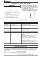
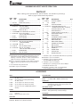
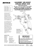
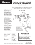
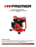
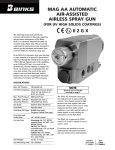
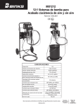
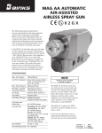
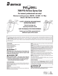
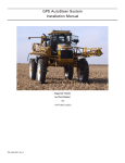
AA4400M AIR-Assist
AIRLESS Spray Gun
(0909-4400-XXXXXX)
English: Pages 1 – 12
Español: Páginas S-1 – S-12
Français: Pages F-1 – F-12
(WITH FLAT TIP/TWIST TIP OPTION,
FAN SIZE ADJUSTMENT FEATURE AND
HVLP/LVMP TECHNOLOGY)
II 2 G X
The following instructions
provide the necessary
information for the proper
operation and preventive
maintenance of the Binks
AA4400M Air-Assist Airless
Spray Gun. Please read and
understand all information in this
document in order to get the
maximum performance from
your new AA4400M spray gun.
In the AA4400M spray gun, the
paint or other material to be
sprayed is pre-atomized and
forced through the carbide tip by
the typical 1,600-3,800 psi fluid
pressure (with capabilities up to
4,400 psi/303 bar). As a result of
the pre-atomizing, the final
shaping air supplied by the air
cap produces an exceptionally
fine and even spray pattern. The
result of this spray pattern is an
even finish that lends itself to
products that need an
exceptionally fine finish with
reduced overspray and VOC
emissions.
Specifications:
Maximum
Fluid Pressure:4400 psi /303 bar
Maximum
Air Pressure:100 psi /6.8 bar
Gun Body:Forged Aluminum
Fluid Path:Stainless Steel
Fluid Seat:
Tungsten Carbide Seat
Fluid Inlet Size:1/4" NPS(m) Thread
Air Inlet Size:
1/4" NPS(m) Thread
Gun Weight:17.28 oz./490 g
(without Tip, Aircap, Guard)
PROP 65 WARNING
WARNING: This product
contains chemicals known
to the State of California
to cause cancer and birth
defects or other
reproductive harm.
IMPORTANT!
DO NOT DESTROY
It is the customer's responsibility to have
all operators and service personnel read
and understand this manual.
Contact your local Binks representative
for additional copies of this manual.
READ ALL INSTRUCTIONS BEFORE OPERATING THIS BINKS PRODUCT
Replaces
Part Sheet
77-2922R-2
Part
Sheet
77-2922R-3
!
Warning
High Pressure Can cause serious injury if
equipment is installed or used incorrectly.
Read, Understand, and observe
all Warnings and Instructions
in this Manual.
Flammable, Explosive and Toxic Vapors
High Pressure Spray
and Hose Leaks
Operate equipment only after all
instructions are clearly understood.
In this part sheet, the words WARNING, CAUTION and NOTE are used to emphasize important safety information as follows:
!
WARNING
Hazards or unsafe practices which could
result in severe personal injury, death or
substantial property damage.
!
Caution
Hazards or unsafe practices which could
result in minor personal injury, product
or property damage.
NOTE
Important installation, operation or
maintenance information.
Injection Hazard
EQUIPMENT MISUSE HAZARD
Spray from the gun, hose leaks, or ruptured components can inject fluid into
your body and cause extremely serious injury, including poisoning or the need
for amputation. Splashing fluid in eyes or on skin can also cause a serious injury.
• Fluid injected into the skin might look like just a cut, but is a serious injury and
should be treated as such. GET IMMEDIATE MEDICAL ATTENTION. INFORM THE
PHYSICIAN WHAT TYPE OF MATERIAL WAS INJECTED.
• Do not point the spray gun at anyone or any part of the body.
• Do not put fingers or hand over the spray tip.
• Do not stop or detect fluid leaks with a rag, hand, body or glove.
• Do not use a rag to blow back fluid. THIS IS NOT AN AIR SPRAY GUN.
• Engage the gun safety when not spraying.
• ALWAYS RELIEVE THE PRESSURE WHENEVER WORKING ON THE SPRAY GUN.
• Tighten all fluid connections before operating equipment.
• Check all hoses, tubes, and couplings daily. Replace all worn, damaged, or
loose parts immediately.
• This equipment is for professional use only.
• Read and understand all instructional manuals, tags, and labels before operating equipment.
• Use the equipment only for its intended purpose. If you are unsure about its
purpose call your local Binks distributor.
• Do not alter or modify this equipment. Use only genuine Binks parts.
• Do not exceed the maximum working pressure of the lowest rated system
component. THE MAXIMUM RATING OF THE AA4400M IS 4400 PSI (303 BAR)
FLUID PRESSURE. DO NOT EXCEED THE FLUID PRESSURE RATING.
• Route all hoses away from all sharp edges, moving parts, hot surfaces and
high traffic areas.
• Do not use hoses to pull the equipment.
• Use only Binks approved hoses. Do not remove spring guards from hoses,
these are on the hoses to prevent rupture from kinking at the connectors.
• Use only solvents compatible with hoses and wetted parts of the equipment
used.
• Comply with all applicable local state and national fire, electrical, and other
safety regulations.
!
WARNING
For pressures over 1000 psi the tip guard must be in place for
added protection against skin injection.
Improper grounding, poor air ventilation, open flames, or sparks can cause a
hazardous condition and result in fire or explosion and cause serious injury.
FIRE AND EXPLOSION HAZARD
Hazardous fluids or toxic fumes can cause serious injury or death if splashed on
• Ground the equipment and object being sprayed.
skin or in the eyes, swallowed or inhaled.
• Provide fresh air ventilation to avoid the build up of flammable fumes from
the material being sprayed or from solvent.
TOXIC FLUID HAZARD
• Extinguish all open flames or pilot lights in spray area.
• Know the specific hazards of the fluid you are using. This information is on the • Electrically disconnect all equipment in the spray area.
• Keep the spray area free from all debris, including solvent rags.
MSDS for the material being used. Read all fluid manufacturer’s warnings.
• If there is any static sparking while using the equipment, STOP SPRAYING
• Store hazardous fluids in approved containers only. Dispose of all hazardous
IMMEDIATELY. Identify and correct problem.
fluids in accordance with all state, local and national guidelines.
• Wear the appropriate protective clothing, gloves, eyewear and respirator.
NOISE LEVELS
Equipment misuse can cause the equipment to fail, malfunction, or start unexpectedly and result in serious injury.
• The A-weighted sound level of spray guns may exceed 85 dB(A) depending
on the setup being used. It is recommended that ear protection is worn at all
times when spraying.
The Spray Gun models listed in the following declaration of conformity may be used in some potentially explosive atmospheres ONLY when
the special conditions for safe installation and operation have been followed as expressed in this user manual (Part Sheet). These models
are approved to ATEX regulations 94/9/EC, protection level: II 2 G X: Suitable for use in Zones 1 and 2.
EC Declaration of Conformity
Manuf. By:ITW Industrial Finishing
195 Internationale Blvd.
Glendale Heights, IL 60139
Type/Series:
Handheld Spray Guns
Model: AA1600M, AA4400M
The equipment to which this document relates is in conformance with the following standards or other normative references:
EN ISO 12100-1&2:2003 and BS EN 1953:1999 and thereby conform to the protection requirements of Council Directive 98/37/
EC relating to Machinery Safety Directive, and;
EN 13463-1:2001, Council Directive 94/9/EC relating to Equipment and Protective Systems for use in Potentially Explosive
Atmospheres, protection level II 2 G X.
Approved By: _ _____________________________ 2
December 3, 2009 Date:_______________
Paul Micheli, ITW Industrial Finishing
ITW Industrial Finishing reserves the right to modify equipment specification without prior notice.
Spray Gun Set-Up
Typical Hook-Up
NOTE
Oil and Water
Extractor
Pump
Before proceeding, make sure trigger lock is engaged.
1.Connect your high-pressure fluid hose to the gun fluid
inlet and tighten securely.
2.Connect your air hose to the gun air connection and tighten securely.
3.Slowly increase air to the pump to obtain a fluid pressure at the gun’s lower end of the pressure range. A typical starting fluid pressure is 250 psi. Actual starting
pressure points may be higher or lower than 250 psi and
depend on the setup including the type of pump used,
the type of material sprayed, and the spray gun itself.
4.Using the control knob on the air regulator, set the air
pressure at zero.
5.To test the spraying pattern, spray a piece of wood or
cardboard with a fast pass about one foot away from the
surface. The results of the test will allow you to determine the uniformity of the particle size and spraying pattern.
6.If the spraying pattern develops tails or is not uniform,
gradually increase the air pressure as necessary to develop a uniform spraying pattern. 14 psi is the maximum
inlet air pressure for HVLP (15 psi max. for HVLP twist
tip cap), or use 20-40 psi inlet air pressure for LVMP.
The HVLP flat tip and twist tip air caps consume 8.3
SCFM air at their respective maximum inlet air pressures. The LVMP flat tip and twist tip air caps consume 13 SCFM at 30 psi inlet air pressure. The air is
used to assist the atomization of the coating.
7.If the quality of spray is acceptable, begin spraying. If
the spraying rate is too slow to keep up with the production line speed, or if the quantity of material sprayed is
inadequate for acceptable coverage, gradually increase
the fluid pressure in 50 psi increments using the fluid
regulator control knob. However, note that as the fluid
pressure increases, more air is needed to eliminate the
tails.
Consistency in spraying can be increased across spray gun
operators and similar spraying jobs by developing pressure
standardization charts. Repeat step 6 until the required material coverage and spraying speed are achieved. If the maximum fluid pressure is reached before the required material
coverage and spraying speed are achieved, you may need to
switch to a larger fluid tip.
Air
In
Regulator
Air
Regulator
Gun
Air
Air
Fluid Filter
Fluid
Figure 1
Fan pattern adjustment: turn knob counterclockwise to
decrease pattern; clockwise to increase pattern (Fig. 2).
Fan
Adjustment
Control Knob
When using the
twist tip air cap,
the primary
purpose of the fan
pattern adjustment
knob is to eliminate
tails in the spray
pattern.
Figure 2
NOTE
For HVLP spray, fan adjustment feature requires 14 psi
max. of air inlet pressure. (15 psi max. for HVLP twist tip.)
For LVMP spray, fan adjustment requires approximately
20-40 psi of air inlet pressure. Higher fluid pressure
requires higher air inlet pressures to accommodate pattern
adjustment.
NOTE
Do not hang gun by trigger. This will cause needle damage
or malfunction.
Fluid Tip Selection
Factors to consider in selecting a fluid tip for an air-assist
airless spray gun include (1) the size of the parts being
sprayed; (2) the production line speed; (3) the material
flow rate and film thickness; (4) the viscosity of the
material applied; (5) the type of material applied; and (6)
the quality of atomization of the coating required.
The selection of a fluid tip necessary to perform a specific spraying job is best determined through a combination
of experimentation and expert advice from your material
and equipment suppliers.
Fluid Hoses
Air-assist airless spray guns operate at fluid pressures
higher than operating pressures of air spray guns. As a
result, when operating an air-assist airless spray gun, it is
critical to select the appropriate fluid hose that is rated for
the pressure range at which the airless gun is operated.
3
Troubleshooting defective spray patterns
!
Caution
Always engage trigger lock and relieve fluid pressure before
servicing gun.
The following procedure summarizes the steps that an
operator must immediately take when the first signs of a
defective spray pattern emerge.
1.Check the external portion of the fluid tip for material
buildup. If buildup has occurred, secure the gun trigger safety switch and clean the gun fluid tip with a
non-metal soft brush.
2.If the spray pattern exhibits signs of tails at the top or
bottom ends of the pattern, increase the air pressure
gradually until the tails disappear.
3.If increasing air pressure does not dissipate the tails,
the fluid tip may be worn and may need to be
replaced. Another sign of the need to replace a worn
tip is a gradual decline in spraying pattern width.
4.If cleaning or replacing the fluid tip does not dissipate
the tails; the spraying defect is most likely due to the
material temperature and/or viscosity.
5.If pattern pulsation or blinking occurs, check the pressure regulators, all downstream regulators, and the
pump. These may require further adjustment or even
repairs.
Tails
Correct
Pattern
Figure 3
General troubleshooting
(Refer to page 12 when referencing part numbers in brackets.)
Problem
Cause
Action
Fluid leaking from
through the seal
Worn seal or needle shaft.
Replace needle assembly (18).
Loose needle seal.
Tighten packing nut gently until leak stops.
Fluid leaking from the
front of the gun
Needle ball worn or damaged.
Replace needle assembly (18).
Worn seat assembly.
Replace fluid seat (3/3A).
Fluid in air passages
Spray tip seal leaking.
Tighten air cap/nozzle guard assembly (7)
Replace carbide tip assembly (5/5A).
Leaking around fluid seat.
Tighten or replace fluid seat (3/3A).
Slow fluid shut off
Fluid buildup on needle assembly.
Clean or replace needle assembly (18).
No fluid output when
triggered
Tip orifice plugged.
For flat tip: Turn off fluid supply. Relieve pressure into a closed earthgrounded container. Engage trigger safety. Remove air cap/nozzle
guard assembly (6) and the carbide tip (5). Clean or replace carbide
tip assembly (5).
For twist tip: Rotate twist tip (5A) in aircap (6A) and spray into a
closed-grounded container to try clear tip of any debris. If that fails
to unplug the tip then remove, clean and replace twist tip.
Needle is damaged or broken.
Fluid filter or fluid hose plugged.
Turn off fluid supply. Relieve pressure into a closed-grounded container. Remove trigger (10). Replace needle assembly (18)
Turn off fluid supply. Relieve pressure into a closed-grounded container. Turn off air supply to pump and relieve fluid pressure with bypass
valve. Engage trigger safety. Very slowly loosen the hose connection
at the gun to relieve any pressure in hose. Remove hose and clear
obstruction. NOTE: When replacing filter, use two wrenches—one to
hold tube (11) in place and prevent twisting, and the other to remove
nut (14). Only tighten nut (14) from 9 to 11 ft.-lbs.
IMPORTANT REGULATORY NOTE
The AA4400M Air-Assist H.V.L.P. hand spray gun combines the proven efficiency of the Binks compliant spray guns with
air-assist atomization to yield a reliable, carefully engineered compliant spray gun. With 25' of 5/16" I.D. air hose and regulator set at only 20 p.s.i. the compliant air cap registers 10 p.s.i. of atomization air to shape and soften the spray pattern. The
AA4400M air-assist H.V.L.P. gun operates at high transfer efficiencies and fully complies with all government regulations for
H.V.L.P. spray guns.
Max. Fluid Input:
Max. static air pressure at regulator with 25' of hose to inlet:
Max. Dynamic Gun Inlet Air Pressure:
Gun Body:
Fluid Path:
4
4400 psi / 303 BAR
20 psi / 1.4 BAR
14 psi / 1 BAR
Forged Aluminum Alloy
Stainless Steel and Tungsten Carbide / UHMW
Spray Pattern troubleshooting
ProblemCauseAction
Fluttering Spray Pattern Insufficient fluid supply.Adjust fluid regulator or fill fluid supply
tanks.
Air in paint supply line.Check and tighten pump siphon hose connections, bleed air from paint line.
Attempting to “feather” (Partially
trigger gun).
Cannot feather with an AA4400M gun.
Striping Spray – Fingers
Carbide tip partially plugged.
Clean or replace carbide tip assembly.
Irregular Pattern
Fluid builds up on carbide tip, or tip
partially plugged.
Clean carbide tip.
On defective side of pattern, air horn
holes are plugged.
Clean air horn holes with solvent and
a soft brush.
Pattern pushed to one side, same
side of air cap gets dirty
On defective side of pattern, air horn
holes are plugged.
Clean air horn holes with solvent and
a soft brush or toothpick.
Air-Assist Airless Spray Gun maintenance and Cleaning
Maintenance of air-assist airless spray guns includes (1)
fluid tip wear and replacement; (2) lubrication; and (3)
cleaning of the gun.
Fluid Tip
Operating an air-assist airless spray gun with a worn fluid
tip will result in increased usage of spraying material and
therefore, HAP emissions. For example, an increase in
the diameter of a tip from 0.015 inch to 0.021 inch due to
wear can result in up to a 100 percent increase in material
consumption and cost. To prevent waste in spraying material and non-value-adding costs, a maintenance schedule
that includes fluid tip inspection and replacement must be
established.
Lubrication
Proper lubrication is essential for optimum spray gun performance. Lubrication allows the equipment to operate
easily and correctly. The spray gun should be lubricated
after each cleaning. The points that need lubrication during the maintenance of air-assist airless spray guns
include the fluid needle packing and trigger pivot point.
Gun lube is used to lubricate the fluid needle packing and
trigger pivot point.
!
Caution
Never immerse the entire gun in solvent or thinners. Some
gun parts will lose their lubricative film and wear more
quickly. Additionally, solvents may carry impurities
throughout the gun body and allow them to clog small air
and fluid passages.
CLEANING
The following steps summarize the procedure for cleaning air-assist airless spray guns:
1.Turn off the atomizing air supply to the gun.
2.Turn off air supply to the pump and relieve fluid pressure. This may be accomplished by opening the
bypass/priming valve, if so equipped.
3.Place the siphon (suction) tube into a solvent container.
If pump is directly immersed in material, remove the
pump and immerse it in a solvent container.
NOTE
Use only compatible solvents that are identified as approved
for cleaning and wash-off use.
4.Place the gun trigger safety switch in the locked position.
5.Remove the fluid tip and place it in a closed solvent
container.
6.Adjust the pump air supply regulator to its lowest
level (counter-clockwise).
7.Place the gun trigger safety switch in the unlocked
position.
8.Turn on the air supply to the pump and close the
bypass/priming valve, if so equipped.
9.Slowly adjust the pump air supply regulator until the
pump begins to cycle.
10.Trigger the gun into a closed container until the fluid
runs clear.
!
WARNING
Failure to reduce pump air supply pressure or to use a
closed container can result in material “bounce-back”.
Material “bounce back” can cause injury and damage.
NOTE
During cleaning, the gun may only be sprayed into a closed
container, never flush the gun into the air or spray booth.
5
Cleaning
(Continued)
11.Using a rag dampened with solvent, wipe the exterior
surface of the gun. Additionally, some solvents are
prohibited from being used for cleaning. The operator
must take care to use only approved cleaning solvents
for equipment cleaning. These materials are clearly
labeled as approved for cleaning and wash off operations. If the operator has any question on selecting
appropriate cleaning solvents, the operator should
consult a supervisor or plant environmental staff.
REPLACING FLUID NOZZLE AND/OR FLUID NEEDLE ASSEMBLY
Reasons to replace nozzle and/or needle assembly:
A) Fluid leak through fluid nozzle.
B) Slow shut off of fluid.
C) No fluid when gun triggered.
!
Nozzle with
gasket
Caution
Always ensure that all fluid and air pressure to the gun has been discharged before proceeding with any repairs.
Fig. 4
Fig. 5
Fig. 6
Fig. 7
Fig. 8
Fig. 9
Fig. 10
Fig. 11
REPLACING THE FLUID NOZZLE
!
Caution
Do not remove fluid tube when replacing the fluid nozzle.
1. Remove air cap along with spray tip. (See fig 4)
2. While fully depressing the trigger remove the fluid nozzle and
gasket. (See fig 5)
3. Check baffle plate for wear. If worn replace with new part.
(See fig 6)
4. While fully depressing the trigger install the new fluid nozzle
and gasket. Torque fluid nozzle from 9 to 11 ft.-lbs. (See fig 5) .
5. Replace the air cap along with spray tip (See fig 4)
REPLACING THE FLUID NEEDLE ASSEMBLY
1. Remove the trigger by removing the trigger screw and trigger
nut. (See fig 7)
2. Completely unscrew needle packing nut. (See fig 8)
3. Unscrew blanking cap and remove the needle spring and pad.
(See figs 9 & 10)
4. Ensure the spring pad has not been worn down and clean the
spring of any debris. (See fig 11)
5. Remove the needle assembly. (See fig 12)
6. Insert new needle assembly and new spring if necessary. (See
figs 12 & 10) Ensure the spring pad is attached to the spring.
7. Screw on blanking cap. (See fig 9)
8. Gently tighten needle packing nut. Do not over tighten.
(See fig 8)
9. Replace trigger, trigger screw and trigger nut. (See fig 7)
10. Operate gun with fluid and adjust tightness of packing nut as
necessary to prevent fluid leak. (See fig 8)
6
Fig. 12
SERVICING AIR VALVE
Reasons to service air valve:
A) Air valve not functioning correctly (may need cleaning).
B) Routine maintenance.
C) Air leaks (advise replacement, see p8)
!
Caution
Always ensure that all fluid and air pressure to the gun has been discharged before proceeding with any repairs.
Fig. 13
Fig. 14
Fig. 15
Fig. 16
Fig. 17
Fig. 18
Fig. 19
Fig. 20
Fig. 21
Fig. 22
Fig. 23
Fig. 24
1. Remove trigger and fluid tube assembly. (See fig 13 & 14)
2. Unscrew air valve using 14 mm wrench. (See fig 15)
3. Remove air valve by gripping stem. (See fig 16)
4. Remove spring with spring pad. (See fig 17)
5. DO NOT REMOVE REAR SEAL FROM GUN BODY.
(See fig 18)
6. DO NOT REMOVE PLASTIC CAGE FROM AIR VALVE
BODY AS THIS MAY DAMAGE THE CAGE. (See fig 19)
7. CLEAN
a. Remove all paint build up. (See fig 20)
b. The 4 poppet holes must be clear. (See fig 21)
c. Stem must be free to float in poppet. (See fig 22)
d. Stem must slide through cage bore with slight resistance
(due to seal).
e. Rear seal must look clean and in position in the bore.
(See fig 18)
f. If any of the above cannot be rectified, replace the air valve.
(See Replacing Air Valve p8)
8. Replace spring ensuring the end with the plastic bearing pad
goes in first. (See fig 17)
9. Insert air valve assembly into gun and carefully feed over the
spring and through the rear seal. (See fig 23)
10. Tighten air valve assembly using fingers first, and then tighten
with 14mm wrench. Torque from 18 to 22 ft.-lbs. (See fig 24)
11. Replace the fluid tube and trigger. (See figs 14 & 13)
12. If there is an air leak through the gun, the air valve may need
replacing. (See Replacing Air Valve p8)
7
REPLACING AIR VALVE
Reasons to replace air valve:
A) Air leak through the gun.
B) Air valve not operating correctly.
!
Caution
Always ensure that all fluid and air pressure to the gun has been discharged before proceeding with any repairs.
1. Remove trigger and fluid tube assembly. (See figs 25 & 26)
Fig. 25
Fig. 26
Fig. 27
Fig. 28
Fig. 29
Fig. 30
Fig. 31
Fig. 32
Fig. 33
Fig. 34
Fig. 35
Fig. 36
2. Unscrew air valve using 14 mm wrench. (See fig 27)
3. Remove air valve by gripping the stem. (See fig 28)
4. Remove spring with spring pad. (See fig 29)
5. Hook out rear seal using Service Tool. (See figs 30 & 31)
6. Clean air valve bores in gun body with the brush supplied in
the kit.
7. Place new rear seal onto Service tool; grooves must fit in
service tool form. (See fig 32)
8. Push rear seal firmly into hole up to shoulder, using Service
tool. (See figs 33 & 34)
9. Insert new spring, ensuring the end with the plastic bearing pad
goes in first. (See fig 29)
10. Insert air valve assembly into gun and carefully feed over the
spring and through the rear seal. (See fig 35)
11. Tighten air valve assembly using fingers first, then tighten with
14 mm wrench. Torque from 18 to 22 ft.-lbs. (See fig 36)
12. Replace fluid tube and trigger. (See figs 26 & 25)
8
TIP GUARD INSTALLATION
REASON TO INSTALL TIP GUARD:
To replace broken tip guard.
!
WARNING
For pressures over 1000 psi the tip guard must be in place for added
protection against skin injection.
!
Caution
Always ensure that all fluid and air pressure to the gun has been discharged before proceeding with any repairs.
Fig. 37
Fig. 38
Fig. 39
Fig. 40
Fig. 41
Fig. 42
INSTRUCTIONS ARE VALID FOR BOTH FLAT TIP GUARD
AND TWIST TIP GUARD:
1. Disconnect all fluid and air hoses from the gun.
2. Insert the gun into a clamping vise with fluid nozzle facing
directly upwards. (See fig 37) Gun should be securely clamped
at the upper portion of the gun handle.
3. Assemble air cap and air cap ring together – less spray tip and
plastic tip guard. (See fig 38)
4. Install the air cap and air cap ring assembly onto the gun until it
is fully hand tightened. (See fig 39)
5. Slip on the plastic tip guard onto the air cap in proper
orientation. (See fig 40)
6. Place round bar screwdriver (approx. 12” long) between open
sections of the plastic guard and push down with even pressure
on both sides of the plastic guard. (See fig 41)
7. The guard should snap into air cap groove securely. (See fig 42)
8. The aircap can now be removed to install the appropriate tip
for use.
9
TWIST Tip Selection Charts
STANDARD FLAT Tip Selection Charts
Fan
width based on 2200 PSI with latex paint 12" from
surface.
Actual results may vary, depending on material
FAn
viscosity.
width
PART NUMBER
Description
orifice
(in.)
GPM
capacity
@2200 PSI
9-307-75
TWIST TIP
0.007
6
0.05
9-309-75
9-409-75 9-509-75
TWIST TIP
TWIST TIP
TWIST TIP
0.009
0.009
0.009
6
8
10
0.09
0.09
0.09
9-311-75
9-411-75
9-511-75
9-611-75 TWIST TIP
TWIST TIP
TWIST TIP
TWIST TIP
0.011
0.011
0.011
0.011
6
8
10
12
0.12
0.12
0.12
0.12
9-313-75
9-413-75 9-513-75 9-613-75 9-713-75 TWIST TIP
TWIST TIP
TWIST TIP TWIST TIP
TWIST TIP
0.013
0.013
0.013
0.013
0.013
6
8
10
12
14
0.18
0.18
0.18
0.18
0.18
9-315-75 9-415-75
9-515-75 9-615-75 9-715-75 TWIST TIP
TWIST TIP
TWIST TIP
TWIST TIP
TWIST TIP
0.015
0.015
0.015
0.015
0.015
6
8
10
12
14
0.24
0.24
0.24
0.24
0.24
9-417-75
9-517-75 9-617-75 9-717-75 TWIST TIP
TWIST TIP
TWIST TIP
TWIST TIP
0.017
0.017
0.017
0.017
8
10
12
14
0.31
0.31
0.31
0.31
9-419-75
9-519-75 9-619-75 TWIST TIP
TWIST TIP
TWIST TIP
0.019
0.019
0.019
8
10
12
0.38
0.38
0.38
9-521-75
9-621-75 TWIST TIP
TWIST TIP
0.021
0.021
10
12
0.47
0.47
9-523-75
9-623-75 TWIST TIP
TWIST TIP
0.023
0.023
10
12
0.57
0.57
9-525-75
9-625-75
TWIST TIP
TWIST TIP
0.025
0.025
10
12
0.67
0.67
9-627-75
TWIST TIP
0.027
12
0.74
9-435-75
TWIST TIP
0.035
8
1.31
9-631-75
9-635-75
TWIST TIP
TWIST TIP
0.031
0.035
12
12
1.03
1.31
FINE FINISH FLAT Tip Selection Charts
Fan
width based on 1000 PSI with water 12" from
surface. Actual results may vary, depending on
FAn
material viscosity.
GPM
capacity
width
@500 PSI
PART NUMBER
Description
orifice
(in.)water
9-0909-F
9-0911-F
FINE FINISH TIP
FINE FINISH TIP
0.009
0.009
9
11
0.039
0.039
9-1109-F
9-1111-F
9-1113-F
9-1115-F
FINE FINISH TIP
FINE FINISH TIP
FINE FINISH TIP
FINE FINISH TIP
0.011
0.011
0.011
0.011
9
11
13
15
0.06
0.06
0.06
0.06
9-1309-F
9-1311-F 9-1313-F 9-1315-F FINE FINISH TIP
FINE FINISH TIP
FINE FINISH TIP
FINE FINISH TIP
0.013
0.013
0.013
0.013
9
11
13
15
0.09
0.09
0.09
0.09
9-1509-F 9-1511-F
9-1513-F 9-1515-F 9-1517-F FINE FINISH TIP
FINE FINISH TIP
FINE FINISH TIP
FINE FINISH TIP
FINE FINISH TIP
0.015
0.015
0.015
0.015
0.015
9
11
13
15
17
0.12
0.12
0.12
0.12
0.12
9-1709-F
9-1711-F 9-1713-F 9-1715-F
9-1717-F
FINE FINISH TIP
FINE FINISH TIP
FINE FINISH TIP
FINE FINISH TIP
FINE FINISH TIP
0.017
0.017
0.017
0.017
0.017
9
11
13
15
17
0.16
0.16
0.16
0.16
0.16
Fan
width based on 1000 PSI with water
12"
from surface. Actual results may vary,
FAn
depending
on material viscosity.
width
GPM
capacity
@500 PSI
(in.)water
PART NUMBER
Description
orifice
114-00702
114-00704
114-00706
114-00708
Tip Assembly
Tip Assembly
Tip Assembly
Tip Assembly
.007
.007
.007
.007
2
4
6
8
.028
.028
.028
.028
114-00902
114-00906
114-00908
114-00910
114-00912
Tip Assembly
Tip Assembly
Tip Assembly
Tip Assembly
Tip Assembly
.009
.009
.009
.009
.009
2
6
8
10
12
.039
.039
.039
.039
.039
114-01104
114-01106
114-01108
114-01110
114-01112
114-01114
Tip Assembly
Tip Assembly
Tip Assembly
Tip Assembly
Tip Assembly
Tip Assembly
.011
.011
.011
.011
.011
.011
4
6
8
10
12
14
.060
.060
.060
.060
.060
.060
114-01304
114-01306
114-01308
114-01310
114-01312
114-01314
114-01316
Tip Assembly
Tip Assembly
Tip Assembly
Tip Assembly
Tip Assembly
Tip Assembly
Tip Assembly
.013
.013
.013
.013
.013
.013
.013
4
6
8
10
12
14
16
.090
.090
.090
.090
.090
.090
.090
114-01506
114-01508
114-01510
114-01512
114-01514
114-01516
114-01518
Tip Assembly
Tip Assembly
Tip Assembly
Tip Assembly
Tip Assembly
Tip Assembly
Tip Assembly
.015
.015
.015
.015
.015
.015
.015
6
8
10
12
14
16
18
.120
.120
.120
.120
.120
.120
.120
114-01706
114-01708
114-01710
114-01712
114-01714
114-01716
114-01718
Tip Assembly
Tip Assembly
Tip Assembly
Tip Assembly
Tip Assembly
Tip Assembly
Tip Assembly
.017
.017
.017
.017
.017
.017
.017
6
8
10
12
14
16
18
.160
.160
.160
.160
.160
.160
.160
114-01906
114-01908
114-01910
114-01912
114-01914
114-01916
114-01918
Tip Assembly
Tip Assembly
Tip Assembly
Tip Assembly
Tip Assembly
Tip Assembly
Tip Assembly
.019
.019
.019
.019
.019
.019
.019
6
8
10
12
14
16
18
.190
.190
.190
.190
.190
.190
.190
114-02110
114-02112
114-02114
114-02116
114-02118
Tip Assembly
Tip Assembly
Tip Assembly
Tip Assembly
Tip Assembly
.021
.021
.021
.021
.021
10
12
14
16
18
.240
.240
.240
.240
.240
114-02410
114-02412
114-02414
114-02416
114-02418
Tip Assembly
Tip Assembly
Tip Assembly
Tip Assembly
Tip Assembly
.024
.024
.024
.024
.024
10
12
14
16
18
.310
.310
.310
.310
.310
114-02710
114-02712
114-02714
114-02716
114-02718
Tip Assembly
Tip Assembly
Tip Assembly
Tip Assembly
Tip Assembly
.027
.027
.027
.027
.027
10
12
14
16
18
.385
.385
.385
.385
.385
TWIST TIP NOTE
When switching from flat tip to twist tip, increase pattern
size by 2 inches and use air adjustment to turn down to
desired size.
Full Gun Assemblies
Description
Ass'y Number
Description
Ass'y Number
AA4400M HVLP FLAT TIP GUN ASSEMBLY (NO TIP INCL.)
0909-4400-HF0000
AA4400M HVLP TWIST TIP GUN ASSEMBLY (NO TIP INCL.)
0909-4400-HT0000
AA4400M LVMP FLAT TIP GUN ASSEMBLY (NO TIP INCL.)
0909-4400-LF0000
AA4400M LVMP TWIST TIP GUN ASSEMBLY (NO TIP INCL.)
0909-4400-LT0000
10
AA4400M AIR-assist AIRLESS spray gun
Parts List
When ordering, please specify Part No. (Not all Part Nos. are available for purchasing.)
Refer to page 12 when referencing Item Nos.
ITEMPART
NO.NO.
DESCRIPTION
1
—
GUN BODY ..................................................... 1
2
SPA-71-K5
BAFFLE PLATE (Kit of 5)................................. 1
QTY.
FLAT TIP COMPONENTS
3 54-5799-K ✙FLUID SEAT (4400PSI)....................................... 1
(Tungsten Carbide) . .................................
4
SPA-98-K5
GASKET (Kit of 5)........................................... 1
5
114-XXXXX ■ FLAT TIP (Fine finish tips 9-XXXX-F)............. 1
6
54-5795-K ▼FLAT TIP HVLP AIRCAP..................................... 1
(Flat Tip LVMP Aircap 54-5797-K)
7
54-5852
RETAINING RING............................................... 1
8
54-5794 m
FLAT TIP GUARD............................................... 1
TWIST TIP COMPONENTS
3A 54-5832-K ✙ TWIST TIP FLUID SEAT (4400PSI)...................... 1
(Tungsten Carbide)
5A 9-XXX-75 ■ TWIST TIP.......................................................... 1
5B 54-5801-K2 TWIST TIP BRACE (Kit of 2)............................ 1
6A 54-5796-K ▼TWIST TIP HVLP AIRCAP................................. 1
(Twist Tip LVMP Aircap 54-5798-K)
7
54-5852
8A 54-5793 m
RETAINING RING............................................... 1
TWIST TIP GUARD............................................ 1
▼All aircap kits are pre-assembled with Retaining ring and
appropriate tip guard. When switching from flat tip to
twist tip, or vice versa, be sure to order correct fluid seat
(3/3A). For twist tip, item 5B will also be needed.
■Refer to page 10 for available tip sizes. When purchasing
twist tip, discard packaged brace/seal and use Item 5B
only.
✙Pre-assembled with gasket SPA-98.
ITEMPART
NO.NO.
DESCRIPTION
QTY.
9 SN-402-K AIR VALVE ASSEMBLY...................................... 1
TRIGGER............................................................ 1
10
— ▲
11 54-5780
FLUID TUBE ASSEMBLY ................................... 1
12 54-5788-K5 oFLUID FILTER 60 MESH (Kit of 5)................... 1 (100 Mesh Filter (Kit of 5) 54-5789-K5)
FLUID INLET SWIVEL (1/4” NPS)....................... 1
13
— ➣
FILTER ADAPTER NUT....................................... 1
14
— ➣
15 SN-9-K3 AIR INLET FITTING 1/4” NPS (Kit of 3)........... 1
FILTER BRACKET SCREW.................................. 1
16
— ●
FILTER BRACKET............................................... 1
17
— ●
FLUID NEEDLE ASSEMBLY (4400PSI)................ 1
18
— k
19 54-5850
BLANKING NEEDLE NUT.................................. 1
NEEDLE SPRING PAD........................................ 1
20
—k
NEEDLE SPRING (4400PSI)................................ 1
21
—k
22 54-5815
SPREADER VALVE ASSEMBLY.......................... 1
23
— #
BODY BUSHING................................................ 1
24
— #
BODY BUSHING GASKET.................................. 1
TRIGGER NUT.................................................... 1
25
— ▲
TRIGGER SCREW............................................... 1
26
— ▲
TOP FILTER SEAL............................................... 1
27
— 6
BOTTOM FILTER SEAL...................................... 1
28
— 6
➣Available as part of kit 54-5838. Order Filter (12) separately.
●Available as part of kit 54-5827.
kAvailable as part of repair kit 54-5826.
(Includes 4400 PSI Fluid Needle.)
#Available as part of kit 54-5829.
mMandatory for operating pressures above 1000 psi.
oAssembled with filter seals.
6Available in 10 pack as part of kit 54-5874-K10
(note assembly location on next page).
▲Available as part of kit 54-5835.
ACCESSORIES
HOSES
FLUID REGULATOR
71-4990 15' Polyurethane Air Tubing ASM w/fittings,
3/8" O.D., 1/4" I.D.
845011 Less Gauge, 1000 to 3000 PSI regulated range
71-4991 25' Polyurethane Air Tubing ASM w/fittings,
3/8" O.D., 1/4" I.D.
71-4992 15' 1/8" High Pressure Fluid Hose Assembly
71-499325' 1/8" High Pressure Fluid Hose Assembly
71-499525' 3/16" Low Pressure (1900PSI Max) Fluid Hose
Assembly
CLEANING KIT
54-4994 Cleaning Kit: Includes one standard stiff nylon pipe
cleaning brush, full-size nylon brush, tip cleaner and
Binks Gunners Mate lubricant.
HVLP AIRCAP TEST KITS
54-5836-K Flat Tip HVLP Aircap Test Kit (Incl Gauge)
FITTINGS
54-4976-K3 3-Pack 1/4" NPT(f) x 3/8" O.D. Push-In Tube Fitting
(optional)
72-2332 845013 Less Gauge, 2000 to 5000 PSI regulated range
Fluid Inlet Swivel (1/4"m x 1/4"f)
54-5837-K Twist Tip HVLP Aircap Test Kit (Incl Gauge)
TEST GAUGES
54-5327 H.V.L.P. Test Gauge
FLUID FILTER
GUN LUBE
54-5788-K5 60 Mesh (Screen) Gun Mounted Filter
6-429 Binks Gunners Mate gun lube, 2 oz. bottle (20/box)
54-5789-K5 100 Mesh (Screen) Gun Mounted Filter
11
XTighten 9 to 11 ft.-lbs.
YTighten 18 to 22 ft.-lbs.
Z DO NOT OVER TIGHTEN.
TWIST TIP COMPONENTS
FLAT TIP COMPONENTS
AA4400M AIR-assist AIRLESS spray gun
WARRANTY
This product is covered by Binks’ 1 Year Limited Warranty.
Binks Worldwide Sales and Service Listing: www.binks.com
North American Office
ITW Industrial Finishing
195 Internationale Blvd.
Glendale Heights, IL 60139
630-237-5000
www.binks.com
Toll Free Customer Service
and Technical Support
800-992-4657
Toll Free Fax
888-246-5732
10/10 © 2010 Illinois Tool Works Inc. All rights reserved. Printed in U.S.A.