1
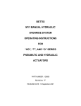
9049 Tyler Blvd. • Mentor, Ohio 44060
Fax (440) 974-0165 • Toll-Free Fax 800-841-8003
snowdoggplows.com
1
16992210 Rev A
TABLE OF CONTENTS
WARNING
Warnings/Vehicle Application...............................pg. 2
About the Plow.....................................................pg. 3
Registration Information/Website.........................pg. 3
Snowplow Mounting/Dismounting.......................pg. 4
Mechanical Installation..................................... pg. 5-6
Harness Installation.......................................... pg. 6-7
Storage and Maintenance....................................pg. 8
Parts Diagram and BOM.................................pg. 9-12
• Lift Frame.....................................................pg. 9
• Moldboard.................................................pg. 10
• Hydraulic Power Unit................................. pg. 11
Hydraulic/Electrical Operation............................pg. 13
Troubleshooting............................................. pg. 14-15
Snow Plowing Tips.............................................pg. 16
Warranty.............................................................pg. 16
DO NOT change blade position when traveling.
WARNING
DO NOT exceed 40 mph when transporting plow.
WARNING
Do not exceed 10 mph when plowing.
WARNING
Always lower blade when vehicle is not in use.
WARNING
Read this manual carefully before operating this
snowplow.
CAUTION
Vehicle application recommendations are based on
the following:
• The vehicle with the snowplow installed must
comply with the vehicle manufacturer's stated
gross vehicle and axle weight ratings (found on the
driver-side door corner post of the vehicle) and the
front and rear weight distribution ratio. In some
cases, rear ballast may be required to comply with
these requirements.
WARNING
Always follow the vehicle manufacturers
recommendations relating to snowplow
installation. For recommended vehicle models
refer to the SnowDogg Application Chart and
Selection Guide.
WARNING
• In some cases there may be additional limitations and requirements.
Make sure plow is properly attached before
moving vehicle.
• Available capacity decreases as the vehicle is
loaded with cargo or other truck equipment, or
snowplow accessories are installed.
WARNING
Do not move plow while servicing or place body
parts between or under plow parts while moving
plow.
• If there is uncertainty as to whether available
capacity exists, the actual vehicle as configured
must be weighed.
2
16992210 Rev A
WELCOME!
Congratulations on your purchase of a SnowDogg plow! The SnowDogg plow by Buyers Products is a heavyduty, professional grade plow built for your toughest plowing applications. By using this manual for maintenance
and safety instructions, you can be sure to optimize the life of your plow.
Your dealer can provide expert assistance and service and is the first line of support. They have first hand
knowledge of your plow and the conditions in your area.
Be sure to register your plow after purchase at www.snowdoggplows.com. The required information is shown on
the Registration Data Sheet. Registration is required to activate your two year warranty.
REGISTRATION DATA SHEET
Owner’s Information
Name: ____________________________________________________________________
Company: _________________________________________________________________
Address: __________________________________________________________________
Phone: ____________________________________________________________________
Fax: ______________________________________________________________________
E-mail: ____________________________________________________________________
Purchased From:___________________________________________________________
Purchase Date:____________________________________________________________
Plow Model: _______________________________________________________________
Plow Serial#: ______________________________________________________________
HPU Serial #: ______________________________________________________________
Truck Model: ______________________________________________________________
Truck Year: ________________________________________________________________
Register your plow at www.snowdoggplows.com to activate your two year warranty.
3
16992210 Rev A
MOUNTED PLOW
DISMOUNTED PLOW
MOUNT/DISMOUNT INSTRUCTIONS
Snowplow Mounting (fig. above)
Snowplow Dismount (fig. above)
1. Check that the pins are fully retracted. The foot
pedal should be pushed towards the truck and will
lock in the retracted position.
2. Drive in to the plow so that the cross bar on the
mount engages with the receiver notch on the plow.
3. Pull the foot pedals away from the truck to release
the pins.
4. Push up on the lift frame to engage the pins. To
verify the lift frame is fully connected, check to see
that the gold pins are visible from each side. Insert the
lock pin through the foot pedal and pedal linkage.
5. Connect the hydraulic control connectors.
1. Put the plow in float by holding the down button for
1 second.
2. Press down on the chain lift to retract the lift cylinder. The chain must have slack for ease of plow
removal.
3. Push on the foot pedals and the lift frame towards
the vehicle simultaneously. The pins will retract and
the lift frame will rotate forward to rest on A-frame.
6. Disconnect the hydraulic connectors
7. Back away from the snowplow
4
16992210 Rev A
INSTALLATION
SnowDogg snowplows are shipped almost completely assembled to minimize the amount of time from box to
plowing. The illustrations are representative only and may differ from your hardware.
Please see the parts diagrams for specific part numbers.
2
8
4
5
1
6
7
3
ITEM
QTY.
PART NO.
1
1
16018100
LIFT FRAME ASSEMBLY
1
16020404
MD60 MOLDBOARD
1
16020410
MD68 MOLDBOARD
3
1
16101110A
TRIP PIN HARDWARE KIT
4
2
16101200
TRIP SPRING
5
1
16101220
TRIP SPRING HARDWARE KIT
6
1
16122100
BLADE GUIDE KIT
7
2
16102142
CLEVIS PIN KIT
8
1
16112400
CHAIN LIFT
2
5
DESCRIPTION
16992210 Rev A
SNOWPLOW ASSEMBLY
1. Attach the chain lift to the upper lift frame and lift cylinder using two 7/8"x3.25" clevis pins and cotter pins.
2. Attach the moldboard (2) to the lift frame using the trip pin hardware kit (3) as shown. Check that the moldboard rotates freely around the trip pins.
3. Install the two trip springs (4) using the trip spring hardware kit (5) as shown. Tension the springs until the coils
are approximately .030 apart. A playing card serves as an adequate measuring device. It is important that all
springs be at the same tension.
4. Grease all greasable fittings (trip pins and king bolt).
VEHICLE SPECIFIC MOUNT INSTALLATION
1. Mount the undercarriage as shown in the undercarriage installation instructions. As with the plow, all the fasteners should be checked on a regular basis.
CAUTION
For safety reasons, the blade drops very slowly on the plow as shipped. To adjust the drop speed of the blade
use a flat blade screwdriver and turn the lowering speed adjustment on the front of the hydraulic power unit
counter clockwise. Turn it clockwise to slow the blade drop speed. Do this only while the blade is dropped,
and tighten the jam nut after adjusting.
HARNESS INSTALLATION
The plow side control harness has been preinstalled. The truck side control harness is routed through the
grill, by the battery, and through the firewall to the controller. It is preferable when possible to keep the plow
connector on the drivers side to make mount/dismount easier and faster.
1. Route the CONTROL HARNESS through the truck grill, by the battery, and through the firewall. Some trucks will
require drilling a ø1.50" hole through the firewall, while some will have holes provided (usually plugged). Check your
truck Owner’s Manual for details. If the hole is drilled it is critical that a grommet be used to prevent damage to the
wire harness.
2. Mount the MOTOR RELAY in a convenient and secure location on the battery side of the vehicle using the included self tapping screws.
3. The small RED WIRE from the CONTROL HARNESS is connected to a small terminal of the MOTOR RELAY.
4. The small BLACK WIRE from the CONTROL HARNESS has two leads – one is connected to the other small terminal of the MOTOR RELAY. The other is connected directly to vehicle/chassis ground.
5. The large (4 gage) BLACK WIRE on the CONTROL HARNESS must be connected directly to the NEGATIVE (-)
battery terminal. A BATTERY TERMINAL ADAPTER may be required.
6. The large (4 gage) RED WIRE on the CONTROL HARNESS is connected to one of the large terminals on the
MOTOR RELAY.
7. The shorter red BATTERY CABLE is used to connect the other large terminal of the MOTOR RELAY with the
POSITIVE (+) terminal on the battery. A BATTERY TERMINAL ADAPTER may be required.
8. The CONTROLLER CONNECTOR is routed through the firewall. Wait to complete RELAY HARNESS installation before further steps.
9. Connect the handheld controller and locate in a convenient location for the operator using the included
mounting bracket or Velcro.
10. Male spade connectors on the BLACK and RED/WHITE wires are not used in this application and should be
taped/covered.
6
16992210 Rev A
Control Harness Diagram
TRUCK FIREWALL
DRILL Ø1.5" HOLE AND
PROTECT WITH GROMMET
10A FUSE
TO
CONTROLLER
TO ACC POWER
(+12V)
POSITIVE (+)
TERMINAL
NOT USED
TO CHASSIS OR
BATTERY GROUND
RED/ WHITE
BL ACK
BL ACK
NEGATIVE (-)
TERMINAL
RED
RED 4G A
BL ACK 4G A
THROUGH GRILL
16160300 CONTROL HARNESS
7
16992210 Rev A
Your plow is now ready for operation. The hydraulic system has been filled at the factory and should be fully
operational. It is possible that agitation due to the shipping has introduced some air into the oil. When operating
the plow for the first time some oil may exit the vent (by the coils). This should stop once the plow is cycled
and operational. Check all plow and light functions. If something is not working correctly, reread the installation
directions to make sure a step was not missed and check the schematics.
STORAGE
1. Before disconnecting the plow from your vehicle, fully compress the lift cylinder
2. Disconnect the plow from your vehicle
3. Coat all electrical connection points with dielectric grease
4. Repair/touch up any chipped paint or rusted areas
5. Apply a coat of oil or grease to all exposed chrome (on angle and lift cylinders)
6. Grease all grease fittings on trip pins and king pin
REMOVAL FROM STORAGE
1. Check all fasteners and hydraulic fittings for tightness.
2. Replace any cracked hydraulic hoses
3. Coat all electrical connection points with dielectric grease
4. Connect plow to vehicle
MAINTENANCE
The SnowDogg line of plows has been simply designed for reliable service. In order to ensure the reliability of
your plow, observe the following maintenance items and regularly inspect:
• Fasteners and retaining devices for proper installation and tightness.
• Hydraulic cylinders for damage, pitting or leakage
• Hydraulic hoses for wear, damage or leakage. Replace any damaged hose.
• All electrical connections for corrosion – apply dielectric grease as required
• Cutting edge wear
• Plow shoe wear
• Greasable fittings (2x trip pins and king pin)
HYDRAULIC SYSTEM
• All SnowDogg plows use SnowDogg brand Low-Temperature Hydraulic Fluid (P/N 16150010) available from
SnowDogg dealers.
• The reservoir should be filled through to top port until oil reaches the top port.
• Recheck and tighten all fittings and valves every season or as necessary. Vibration due to normal use can
cause fittings to loosen.
• Loctite or Teflon tape should not be used on any fittings or hoses. The only plugs where pipe sealant may be
used are the reservoir plugs.
• The reservoir should be drained and refilled every season to ensure that the oil remains free of water and
contanimants. If contaminants are known to be present, it is recommended that the reservoir be removed and
cleaned.
With proper maintenance and care your SnowDogg plow will provide years of trouble free service!
8
16992210 Rev A
Figure A - Lift Frame Diagram
30
12
16
189
70
71
87
75
67a
73b
68
72
73a
Figure B - Linkage Detail Diagram
9
16992210 Rev A
Figure C - Moldboard Diagram
37
14
2
3
36
13
4
7
38
24
35
34
26
1
29
15
75
69
10
12
27
16992210 Rev A
Figure D - Hydraulic Power Unit Diagram
66
76
65
50
64
63
61
67
62
58
69
55
56
54
71
52
51
60
189
LIFT
59
53
PS
DS
DROP SPEED ADJUST
68
Hydraulic Power Unit Wiring
ORANGE WIRE
SC
RED WIRE
SB
SA
BLACK WIRE
GREEN WIRE
BLUE WIRE
BLACK WIRE (3 PLACES)
11
16992210 Rev A
9049 Tyler Blvd. • Mentor, Ohio 44060
Phone (440) 974-8888 • Fax (440) 974-0165
Toll-Free Fax 800-841-8003 • snowdoggplows.com
Parts List
REF
1
2
3
4
4
4
4
7
7
7
12
13
14
15
16
16
17
17
18
18a
22a
23a
24
26
27
29
30
32a
34
34
34
35
36
36
37
38
50
51
51
52
53
54
54
54
55
56
58
59
60
61
PN
Qty DESC
16101110A 1 Trip Pin Kit (x2)
16101200
2 Trip Spring
16101220
1 Spring Mount Eye Bolt Kit (x2)
16101150
1 Bolt, Pivot w/grease fitting
16101152
1 Nut, Jam, 1-14
16101515
1 Grease Fitting, Press In
16102104
1 Washer, 1in
16101160
1 Screw, Hex Head, 3/4-10 x 4.00, GR5
16101162
1 Nut, Jam, 3/4-10
16101164
1 Washer, 3/4
16102142
7 Clevis Pin Kit, 7/8 x 3-1/4
16122100
1 Blade Guide Kit
16103000
1 Chain, 5/16 Grade 43, 24 Links
16103020
1 U-bolt Kit
16110140
1 Lift Frame Assembly, VUT/MUT
16112140
1 Lift Frame Weldment, VUT/MUT
16111151
2 Lock Pin Kit, MD
16112102
2 Lock Pin
16112104
2 Mount Spring
16102104
2 Washer, 1in
16111113
2 Foot Pedal
16111111
2 Pedal Linkage
16112220
1 A-Frame
16112230
1 Stand
16111128
1 Snapper Pin W/Lanyard
16112310
1 Sector
16112400
1 Chain Lift Assy
16111124
2 Snapper Pin, 2-1/2in
16120116
1 Cutting Edge Hdw Kit, MD68/MUT/VUT
16120705
1 Cutting Edge, 80in, Rubber
16120506
1 Cutting Edge, 72 x 1/4
16120114
1 Cutting Edge Hdw Kit, 5/8-11, 14 pcs
16121410
1 Skin, MD68, SST
16121406
1 Skin, MD60, SST
16120110
1 Moldboard Skin Hardware Kit
16120122
2 Cap, Crosstube
16151000
1 HPU, Straight Blade
16151100
1 Gear Pump
16159116
1 Shaft Seal
16151102
1 Inlet Strainer w/Elbow
16151106
1 Coupler Spline
16151110
1 Reservoir Kit
16151114
1 Reservoir Fastener Kit (4 Cap Screws; 8 Flat
Washers)
16159114
1 Reservoir Seal Kit
16151112
2 Plug, 3/8 NPT
16151200
1 Motor, 2HP
16151302
1 Main Relief Valve
16151304
1 Crossover Relief Valve, 2800PSI
16151306
1 Angle Lock Valve
16151308
1 Lift Check Valve
REF
61
62
63
63
63
64
64
65
65
66
67
67a
68
69
69a
70
71
71
72
73a
73b
75
75
75
75
76
85
85
85
87
87
87
87
88
89
98
98
98
98
98
98
101
103
106
107
112
112a
189
ACC
OPT
12
PN
16900010
16151310
16151312
16159102
16159103
16151314
16159104
16151316
16159106
16151318
16151320
16151325
16151322
16151324
16151329
16152100
16152128
16152110
16153100
16153192
16153190
16154214
16154220
16154216
16154220
16151326
16160300
16160310
16160604
16160400
16160402
16160404
16160512
16160410
16160500
16160600
16160610
16160620
16160630
16160640
16160650
16101001
16101003
16101006
16101007
16111118
16111126
16151321
16150010
16121350
Qty DESC
Lift Check Removal Tool
1 Lowering Speed Valve
1 Solenoid Valve, 2-way, Normally Closed
1 Seal Kit, 16151312/16151330
1 Screen, 16151312
1 Solenoid Valve, 3-way, Selector
1 Seal Kit, 16151314
1 Solenoid Valve, 4 Way, Reversing
1 Seal Kit, 16151316
3 Coil, 8 size, Dual Spade
1 Connector, -4 BSPP/JICM
1 Connector, -4 SAEM/JICM
4 Elbow, -6 JICM/JIC Swivel
2 Connector, -6 JICM/SAEM
2 Elbow, -6SAEM to -4JIC
1 HPU Cover
1 Cable Grommet
1 Tray
1 Hose, 1/4 x 18, -4 JIC
1 Hose, 1/4 x 22, -6 JIC
1 Hose, 1/4 x 36, -6 JIC
1 Cylinder Gland Nut, 1-1/2in V Pack
1 Cylinder, 1-1/2 x 6 Polypak
2 Cylinder Gland Nut, 1-1/2in Polypak
2 Cylinder, 1-1/2 x 6 Polypak
1 Vent
1 Truckside Control Harness
1 Repair End, 16160300
1 Mini Firewall Adapter, Straight Only
1 Plowside Control Harness
1 Large Spring Cage Kit (2)
6 Small Spring Cage
1 Grill Connector Cap
1 Motor Relay
1 Battery Cable
1 Plow Controller
Controller Extension Harness, 36in
1 Controller Mount Kit
1 Keypad, Rubber
1 Circuit Board, 16160600
1 Coil Cable, Controller
2 Screw, Hex Head 3/8-16 x 1.00 SST
2 Screw, Hex Head 3/8 - 16 x 2.50
4 Nut, Nylock, 3/8-16 SST
6 Washer, 3/8 SST
2 Roll Pin, 1/4 x 2
2 Clevis Pin Kit, 1/4 x 1-1/2
1 Elbow, -4 JICM/JIC Swivel
Hydraulic Fluid, Low Temp, 1 CASE (12 QTS)
2 Shoe Assembly
16992210 Rev A
CONTROLLER FUNCTION
After hitting POWER, the SnowDogg logo should be
lit and the controller status light (upper right corner)
should be solid GREEN. If the status light is blinking,
see troubleshooting.
Lift Button
Plow lifts until lift cylinder is at end of stroke and fluid
is diverted over the main relief valve at 1900PSI.
Right Button
Plow right side moves towards the truck. At the end
of stroke, fluid is diverted over the main relief valve at
1900 PSI.
Left Button
Plow left side moves towards the truck. At end of
stroke, fluid is diverted over the main relief valve at
1900 PSI.
Lower Button
Plow drops until the blade hits the ground or until the
cylinder is fully retracted.
Float (hold Lower Button for >.5 seconds)
Float light is lit and plow drops until the blade hits the
ground or until the cylinder is fully retracted – and the
drop valve remains energized allowing the blade to
follow the ground (depending on how the chain is set).
LOGIC TABLE
LIFT
LOWER
FLOAT
LEFT
RIGHT
MOTORSA
1-
-
1
-
1
1
-
1
-
SB
SC
1-
-
-
-
1
NOTE
Full schematics and pin out information can be
found online at www.snowdoggplows.com under
Tech Support in the 16992910 service manual.
13
16992210 Rev A
TROUBLESHOOTING
SYMPTOM/DIAGNOSTIC
RESULT
FIX
CONTROLLER BLINKING
Plow working normally?
Clean and check all connectors
1 blink
No Motor
Check MOTOR RELAY and wires
2 blinks
Will not Drop
Check BLUE WIRE/ SA COIL
3 blinks
Will not Lift
Check GREEN WIRE / SB COIL
4 blinks
Will not go Right
Check ORANGE WIRE / SC COIL
PUMP MOTOR NOT RUNNING WHEN UP, LEFT OR RIGHT PRESSED
Check voltage at MOTOR terminals with UP, LEFT,
or RIGHT buttons pressed
If voltage present - MOTOR is bad
Replace MOTOR
Check cable continuity between MOTOR RELAY
and MOTOR
If no continuity, check cable, connections, and
replace if necessary
Replace/repair cable or connections
Check control signal to MOTOR RELAY (small
wires to motor relay) with UP, LEFT, or RIGHT
buttons pressed
If voltage present and no click is heard when
buttons are pressed, MOTOR RELAY is bad
Replace MOTOR RELAY
Check ground continuity between between control
ground at MOTOR RELAY and battery ground
If no continuity, check cable, connections, and
replace if necessary
Replace/repair cable or connections
PLOW WON'T MOVE AT ALL, MOVES "JERKILY", VERY SLOWLY, OR CHATTERS
Check fluid level in reservoir
Fluid should be visible from fill cap - reservoir
should be ~3/4 full
Add fluid
Air in fluid
Bleed air from system
Slightly loosen fittings to angle cylinders and angle
the plow. Tighten fittings while fluid is escaping.
Do this over an absorbent mat, or hold a rag over
fitting to absorb excess fluid.
If no voltage present, check cable and
connections
Replace/repair cable or connections
PLOW WON'T DROP
Check voltage at SA VALVE coil
Confirm BLUE wire at SA VALVE
Check DROP SPEED control valve
DROP SPEED valve should be several turns from
fully closed
Open DROP SPEED valve
Check SA VALVE for contamination
Poppet must move freely, and seat area must be
clear of any debris
Remove SA VALVE and check free movement of
poppet, clean any chips/debris from poppet seat
Replace SA VALVE
Check LIFT LOCK valve for contamination
Poppet must move freely, and seat area must be
clear of any debris
Remove LIFT LOCK valve and check free
movement of poppet, clean any chips/debris from
poppet seat
Replace LIFT LOCK valve
Lift Cylinder packing is too tight or damaged
Loosen lift cylinder packing nut 1/4 turn or repack
cylinder
PLOW WON'T LIFT OR WON'T ANGLE IN EITHER DIRECTION
Check voltage at SB VALVE coil
If no voltage present, check cable and
connections
Replace/repair cable or connections
Confirm GREEN wire at SB VALVE
Check SB VALVE for contamination
Spool must move freely, and seat area must be
clear of any debris
Remove SB VALVE and check free movement of
spool, clean any chips/debris from valve
Replace SB VALVE
14
16992210 Rev A
TROUBLESHOOTING, continued
SYMPTOM/DIAGNOSTIC
RESULT
FIX
PLOW WON'T ANGLE IN ONE DIRECTION
Check voltage at SC VALVE coil
If no voltage present, check cable and
connections
Replace/repair cable or connections
Confirm ORANGE wire at SC VALVE
Check SC VALVE for contamination
Spool must move freely, and seat area must be
clear of any debris
Remove SC VALVE and check free movement of
spool, clean any chips/debris from valve
Replace SC VALVE
PLOW DRIFTS WHILE PLOWING SNOW
Air in Fluid
Bleed air from system
Slightly loosen fittings to angle cylinders and angle
the plow. Tighten fittings while fluid is escaping.
Do this over an absorbent mat, or hold a rag over
fitting to absorb excess fluid.
Check ANGLE LOCK valve for contamination
Poppet must move freely, and seat and piston area
must be clear of any debris
Remove ANGLE LOCK valve and clean
Check CROSS RELIEF valve for contamination
Poppet must move freely, and seat must be clear
of any debris
Replace ANGLE LOCK valve
Remove CROSS RELIEF valve and clean
Replace CROSS RELIEF valve
OIL IS LEAKING FROM CYLINDERS
Packing is loose
Tighten until leak stops
Rods are pitted
Polish rods with fine steel wool
Replace cylinder
OIL SPRAYS OUT OF VENT PORT IN POWER UNIT
Air in Fluid
Bleed air from system
Slightly loosen fittings to angle cylinders and angle
the plow. Tighten fittings while fluid is escaping.
Do this over an absorbent mat, or hold a rag over
fitting to absorb excess fluid.
Check fluid level
Fluid should be visible in elbow fitting at end of
reservoir.
Remove fluid if necessary - in most cases the
problem will subside as entrapped air dissipates.
PLOWING TIPS
• Know the area you are plowing. Be aware of all hidden obstacles (pipes, drains, berms, etc.)
• Plow with the storm, do not let snow accumulate
• Always lower the plow blade when parking to minimize the risk of the plow dropping and to reduce the load on
the truck suspension.
• When transporting the plow – monitor coolant temperature. If the truck is running hot, adjust the plow position
to allow additional airflow to the radiator.
• Plowing at high speeds increases the potential for damage to your plow AND your truck
15
16992210 Rev A
PLOWING TIPS
• Know the area you are plowing. Be aware of all hidden obstacles (pipes, drains, berms, etc.)
• Plow with the storm, do not let snow accumulate
• Always lower the plow blade when parking to minimize the risk of the plow dropping and to reduce the load on
the truck suspension.
• When transporting the plow – monitor coolant temperature. If the truck is running hot, adjust the plow position
to allow additional airflow to the radiator.
• Plowing at high speeds increases the potential for damage to your plow AND your truck
Limited Warranty
COVERAGE
Buyers Products Company warrants to the original purchaser of a Buyers Products SnowDogg® brand snowplow that they will be
free from defects in materials and workmanship for a period of two (2) years after the date of original purchase. Buyers Products
warrants accessories, service parts, and components purchased separately to be free of defects in materials and workmanship for a
period of one (1) year after date of original purchase. These warranties are exclusive and in lieu of all other express and, except to the
extent prohibited by applicable law, all implied warranties, including but not limited to the implied warranties or merchantability and
fitness for a particular purpose, are limited in duration to the duration of this warranty.
Buyers Product’s Liability is expressly limited to repair or replacement of defective parts. Buyers Products shall not be liable for
consequential, incidental or contingent damages whatsoever, even if damages are caused by the negligence or fault of Buyers
Products. This warranty gives you specific legal rights. Additional purchaser’s rights may vary from state to state.
WHAT IS NOT COVERED
The warranty does not apply to:
…parts not furnished by Buyers Products or damage resulting from same.
…parts modified without authorization or damage resulting from same.
…expendable parts (cutting edges, fluids, etc.).
…damage resulting from failure to install, maintain or operate the product per the owner’s manual,
installation instructions, or application guides.
…damage to vehicle and/or frame of vehicle resulting from plow attachment.
WARRANTY PROCEDURE
If any part is proven to be defective within that warranty period, Buyers Products will, at its sole discretion, repair or
replace said part at its expense FOB Cleveland, OH. Labor will be credited to authorized dealers as determined by
published rate charts.
Buyers Products obligation shall be limited to such repair or replacement and shall be further contingent on Buyers Products
receiving written notice of the alleged defect and proof of original purchase within ten (10) days of its discovery as well as the return
of the allegedly defective part to Buyers Products. To obtain service, the purchaser must return the defective snowplow to an
authorized SnowDogg Dealer with proof of purchase and applicable maintenance records. All transportation costs to and from the
dealer will be the responsibility of the purchaser. SnowDogg dealers may be located on-line at
www.snowdoggplows.com.
Buyers Products
9049 Tyler Blvd.
Mentor, OH 44060
Contact Your Dealer for Service and Technical Support
16
16992210_A