1
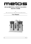
BULK BREWING COFFEE MACHINE
METOS COMBI
CB
TYPE: 5, 1x5R, 1x5L, 2x5, 10, 1x10R, 1x10L, 2x10, 20, 1x20R, 1x20L, 2x20
User Manual
S/N:
Rev.: 2.2
13.2.2006
Rev. 2.2
Dear Customer,
Congratulations on deciding to choose a Metos appliance for your kitchen activities. You
made an excellent choice. We will do our best to make you a satisfied Metos customer
like thousands of customers we have around the world.
Please read this manual carefully. You will learn correct, safe and efficient working methods in order to get the best possible benefit from the appliance. The instructions and hints
in this manual will give you a quick and easy start, and you will soon note how nice it is
to use the Metos equipment.
All rights are reserved for technical changes.
You will find the main technical data on the rating plate fixed to the equipment. When you
need service or technical help, please let us know the serial number shown on the rating
plate. This will make it easier to provide you with correct service.
For your convenience, space is provided below for you to record your local Metos service
contact information.
METOS TEAM
Metos service phone number:...............................................................................................
Contact person:....................................................................................................................
13.2.2006
Rev. 2.2
13.2.2006
Rev.
1. General .......................................................................................................... 1
1.1 Symbols used in the manual .......................................................................................... 1
1.2 Symbols used on the appliance ...................................................................................... 1
1.3 Checking the relationship of the appliance and the manual .......................................... 1
2. Safety .............................................................................................................. 2
2.1 Warnings ........................................................................................................................
2.1.1 Installation .............................................................................................................
2.1.2 Use .........................................................................................................................
2.1.3 Maintenance and troubleshooting ..........................................................................
2.2 Safeguards .....................................................................................................................
2.2.1 On/off switch .........................................................................................................
2.2.2 STOP button ..........................................................................................................
2.2.3 Swivel arm and container detection .......................................................................
2.2.4 Dry-boil protection ................................................................................................
2.2.5 Warning indication display ....................................................................................
2.3 Disposal of the appliance ...............................................................................................
2
2
2
2
3
3
3
3
3
3
4
3. Functional description .................................................................................. 5
3.1 General .......................................................................................................................... 5
3.2 Models ........................................................................................................................... 5
3.3 Application of the appliance .......................................................................................... 6
3.3.1 Prohibited use/Use for other purposes ................................................................... 6
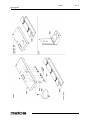
3.4 Construction [1x5, 1x10, 1x20, 2x5, 2x10, 2x20] ........................................................ 7
3.5 Construction [5, 10, 20] ................................................................................................ 9
3.6 Operating switches and indicator lights [5, 10, 20, 1x5, 1x10, 1x20, 2x5, 2x10, 2x20]
11
3.7 Display [5, 10, 20, 1x5, 1x10, 1x20, 2x5, 2x10, 2x20] ............................................. 12
3.8 Error reporting symbols ............................................................................................... 12
4. Operation instructions ............................................................................... 13
4.1 Before using the appliance ..........................................................................................
4.1.1 Flushing the flow heater system ..........................................................................
4.1.2 First settings operator menu .................................................................................
4.2 Operation procedures ...................................................................................................
4.2.1 Brewing coffee .....................................................................................................
4.2.2 Brewing tea ..........................................................................................................
4.2.3 Timer function .....................................................................................................
4.2.4 Temperature protection ........................................................................................
4.2.5 The operator menu [5, 1x5, 10, 1x10, 20, 1x20, 2x5, 2x10, 2x20] ....................
13
13
14
14
15
17
17
18
19
13.2.2006
4.2.6 Menu functions ....................................................................................................
4.2.7 Settings step by step .............................................................................................
4.3 After use ......................................................................................................................
4.3.1 Cleaning ..............................................................................................................
4.3.2 Periodic descaling activities .................................................................................
Rev.
19
20
35
35
37
5. Installation ................................................................................................... 39
5.1 General ........................................................................................................................
5.2 Unpacking [1x5, 1x10, 1x20, 2x5, 2x10, 2x20] ..........................................................
5.3 Unpacking [5, 10, 20] ..................................................................................................
5.4 Preparation for positioning ..........................................................................................
5.5 Water connection .........................................................................................................
5.5.1 Water treatment ....................................................................................................
5.6 Water drainage .............................................................................................................
5.7 Electrical connection ...................................................................................................
5.8 Connection on a counter [1x5, 1x10, 1x20, 2x5, 2x10, 2x20] ....................................
5.9 Mounting on a wall [5, 10, 20] ....................................................................................
39
40
41
41
42
42
42
43
44
44
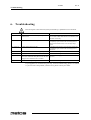
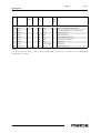
6. Troubleshooting .......................................................................................... 46
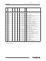
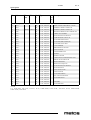
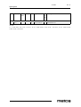
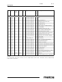
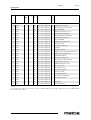
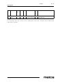
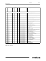
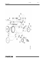
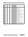
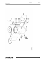
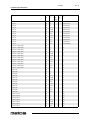
7. Spare parts .................................................................................................. 47
7.1 Voltage codes .............................................................................................................. 49
7.2 Product codes ............................................................................................................... 49
8. Technical specifications .............................................................................. 95
13.2.2006
Rev. 2.2
General
1. General
Carefully read the instructions in this manual as they contain important information regarding proper, efficient and safe installation, use and maintenance of the appliance.
Keep this manual in a safe place for eventual use by other operators of the appliance.
The installation of this appliance must be carried out in accordance with the manufacturer’s instructions and following local regulations. The connection of the appliance to the
electric and water supply must be carried out by qualified persons only.
Persons using this appliance should be specifically trained in its operation.
Switch off the appliance in the case of failure or malfunction. The periodical function
checks requested in the manual must be carried out according to the instructions. Have the
appliance serviced by a technically qualified person authorized by the manufacturer and
using original spare parts.
Not complying with the above may put the safety of the appliance in danger.
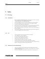
1.1
Symbols used in the manual
This symbol informs about a situation where a safety risk might be at hand. Given instructions are mandatory in order to prevent injury.
This symbol informs about the right way to perform in order to prevent bad results, appliance damage or hazardous situations.
This symbol informs about recommendations and hints that help to get the best performance out of the appliance.
This symbol informs about a function that has to be taken into account in self-control.
1.2
Symbols used on the appliance
This symbol on a part informs about electrical terminals behind the part. The removal of
the part must be carried out by qualified persons only.
1.3
Checking the relationship of the appliance and the manual
The rating plate of the appliance indicates the serial number of the appliance. If the manuals are missing, it is possible to order new ones from the manufacturer or the local representative. When ordering new manuals it is essential to quote the serial number shown
on the rating plate.
1
13.2.2006
Rev. 2.2
Safety
2. Safety
2.1
2.1.1
Warnings
Installation
•
•
•
•
•
•
•
•
•
2.1.2
Use
•
•
•
•
•
•
•
•
2.1.3
Inspect the appliance before using it and check it for damage.
Never submerge or spray the appliance.
Do not press the buttons with a sharp object.
Protect the controls against dirt and grease.
During use some parts will become very hot.
Do not position the container on open fire, or hot plate.
First disconnect the electric cable before transporting the container.
It is advisable to take the plug out of the socket and close the water tap if the appliance is not going to be used for longer periods of time
Maintenance and troubleshooting
•
•
•
2
Place the appliance at buffet height and on a firm, level base, in such a way that it
can be connected to the water supply and power supply.
Connect the appliance to an earthed wall socket.
Position the appliance in such a way that no damage can be caused if it leaks.
Do not tilt the appliance, always position and move the appliance upright.
Connect an overflow pipe to the drainage tube.
Water always remains in the heating system: for this reason the appliance must not
be placed in an area where the temperature can fall below freezing point.
When installing the appliance, always observe the local rules and use approved
materials and parts.
The Installation chapter must again be followed when repositioning the appliance.
Connect the appliance to the cold water mains.
Observe the descaling intervals indicated by the descaling indicator symbol.
Overdue maintenance to the heating system can result in high repair costs and annulment of the guarantee.
Do not leave the appliance unattended when maintenance is being performed.
13.2.2006
Rev. 2.2
Safety
•
•
•
•
2.2
When descaling the appliance, it is advisable to wear safety glasses and protective
gloves.
Wash your hands after descaling.
Have all repairs carried out by a qualified technician.
The plug must be taken out of the socket if the appliance has to be opened for
cleaning or repairs.
Safeguards
The appliance is fitted with the following safe guards
2.2.1
On/off switch
The on/off switch is used to switch the appliance on and off. Remember that the appliance
can still be live after being switched off! For this reason you should always remove the
plug from the socket to render the appliance voltage-free.
2.2.2
STOP button
The coffee making process can be interrupted at any point using the STOP button located
on the control panel.
2.2.3
Swivel arm and container detection
This appliance is equipped with a safety device through which it is only possible to start
the brewing process if the swivel arm and container are in the correct position. If the swivel arm and/or container are moved out of position during the brewing process, the brewing
process is interrupted, a swivel arm and/or container symbol appears in the display and
there is a sound signal (2x short). Once the positioning fault has been resolved the brewing
process can be restored by pressing the START button.
2.2.4
Dry-boil protection
This appliance is equipped with a dry-boil protection. This protection triggers if the heating elements overheat owing to a fault. Once the fault has been resolved, the dry-boil protection can be reset at the outside of the appliance. The most common cause of the dryboil protection being triggered is not descaling the heating system in time.
2.2.5
Warning indication display
A technical fault is reported by displaying an error code in the display. The relevant problem can be localised and resolved with the help of this code. In this case see chapter 13Troubleshooting.
3
13.2.2006
Rev. 2.2
Safety
2.3
Disposal of the appliance
No appliance lasts forever. When the time comes to discard your appliance it will usually
be possible to return it to your dealer. If this is not the case, ask your municipal council
about the alternatives for recycling the materials. All plastic parts have been given standard codes. The parts of the appliance such as the printed circuit board and accompanying
parts form electrical and electronic waste. The metal body is made of stainless steel and
can be completely dismantled.
4
13.2.2006
Rev. 2.2
Functional description
3. Functional description
3.1
General
The ComBi-line 5 - 20 is a professional coffee maker, equipped with a continuous flow
heater. It is very easy to use. The user can choose from a number of fixed set amounts via
a control panel with a graphic display which also offers information about the current
process of the appliance. Specific requirements and wishes concerning brewing quantity,
etc. can be accessed and programmed by the operator via a PIN. The operator also has the
possibility of reading counters and activating a descaling program.
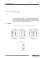
3.2
Models
This manual covers the following coffeemakers of the ComBi-line range:
5
13.2.2006
Rev. 2.2
Functional description
3.3
3.3.1
Application of the appliance
Prohibited use/Use for other purposes
This machine can only be used for brewing and distributing coffee and/or tea. The use of
the appliance for other purposes is not permitted and may be hazardous. The manufacturer
cannot be held liable for losses caused by using the appliance for purposes other than
those indicated here or by incorrect use.
6
13.2.2006
Rev. 2.2
Functional description
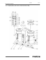
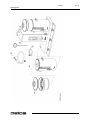
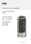
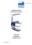
3.4
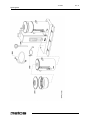
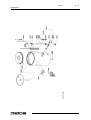
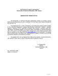
Construction [1x5, 1x10, 1x20, 2x5, 2x10, 2x20]
7
13.2.2006
Functional description
1.
Socket L/R for container heating
2.
ON/OFF switch coffee system
3.
Drip tray with grid
4.
Base plate
5.
8
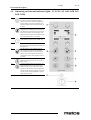
Control panel
5.1
STOP button / Back button (without changing)
5.2
Illuminated display
5.3
Selection button brew volume 1
5.4
Selection button brew volume 2
5.5
Selection button brew volume 3
5.6
Selection button brew volume 4
5.7
START button / Accept button (save)
5.8
Timer button
5.9
On/Off button container heating L/R
6.
Dry-boil protection
7.
Swivel arm
8.
Descale filling opening coffee brewing system
9.
Insulated lid
10.
Blender - transport disk
11.
Water distributor lid
12.
Basket filter
13.
Integrated gauge glass
14.
Handle
15.
Coffee tap
16.
Socket with splash protection
17.
Pilot light
18.
Drain hose coffee brewing system
Rev. 2.2
13.2.2006
Rev. 2.2
Functional description
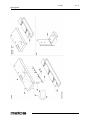
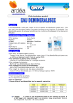
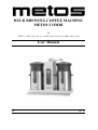
3.5
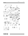
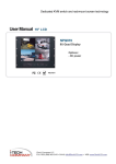
Construction [5, 10, 20]
9
13.2.2006
Functional description
1.
Socket L/R for container heating
2.
ON/OFF switch coffee system
5.
Wall bracket
6.
Control panel
6.2
STOP button / Back button (without changing)
6.3
Illuminated display
6.4
Selection button brew volume 1
6.5
Selection button brew volume 2
6.6
Selection button brew volume 3
6.7
Selection button brew volume 4
6.8
START button / Accept button (save)
6.9
Timer button
6.10 On/Off button container heating L/R
8.
10
Dry boil protection coffee brewing system
9.
Swivel arm
10.
Descale filling coffee brewing system
13.
Drain hose coffee brewing system
Rev. 2.2
13.2.2006
Rev. 2.2
Functional description
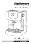
3.6
Operating switches and indicator lights [5, 10, 20, 1x5, 1x10, 1x20, 2x5,
2x10, 2x20]
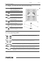
A
Selection buttons (4x) The selection buttons
are used to select the standard brewing
amount. The chosen amount confirmed using the display and can be increased or decreased using the same selection buttons, as
required.
B
STOP buttonUse the STOP button to cancel
a selection or to (emergency) stop a process.
An emergency stop results in the process being lost,so it must be executed again. This
button can also be used as a cancellation button if theoperator menu is activated.
C
On/Off-switchThis switch is used to turn the
coffee making system ON (I) or OFF (0).
D
DisplayThe display informs the user about
the status of the most important functions of
the appliance.
E
START buttonUse the START button to
start a brewing process. First choose the
brewing amount with one of the selection
buttons. This buttoncan also be used as a
confirmation button if the operator menu is
activated.
F
Timer buttonUse the timer button to program the brewing process for use at a later
point of time.
G
Container heating buttons (2x)Use the container heating button to switch the power
sockets that are on the side of the column
ON/OFF. ATTENTION: Only usethe power
sockets for the container heating, do not connect any other electrical appliances. (Maximum capacity 100W).
H
Power socket
11
13.2.2006
Rev. 2.2
Functional description
3.7
Display [5, 10, 20, 1x5, 1x10, 1x20, 2x5, 2x10, 2x20]
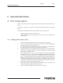
I
Brew volume (4x)Each selection button (4x)
displays a pre-programmed brewing
amount. The amountscan be set completely
as required via the settings menu.
J
ClockReal time indicator
K
Timer; (flashing)The timer function is activated.
L
Scale indicatorOne of the systems must be
descaled at the first opportunity. Look up
'descaling' in theoperator menu.
M
Swivel arm in positionThe swivel arm is in
the correct position above a filter. If the
swivel arm is moved away the symbol disappears from the display.
N
Container in positionThe coffee container
with filter unit is in the correct position. If
the container is taken away the symbol disappears from the display.
O
Container heatingThe heating of the coffee
container is switched on. If the heating is
switched offthe symbol disappears from the
display.
P
Leaking outThe dripping symbol is displayed if the hot water dosing is stopped and
the filter unit is leaking.
3.8
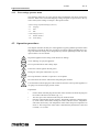
Error reporting symbols
Container position failureThis symbol appears in the display if the coffee container gets out of
position during a brewing process. The arrow shows on which side the problem occurs.
Swivel arm not in positionThis symbol appears in the display if the swivel arm gets out of position
during a making process. The arrow shows on which side the problem occurs.
Swivel arm not in position for new brewing process This symbol appears in the display if a brewing process is started and there is (still) no swivel arm in position above the filter unit.
Press START buttonThis symbol appears after the swivel arm and/or container fault has been resolved. For your own safety the start button must always be pressed again. If this report is responded to within 10 minutes the brewing process will restart and be completed.
If the START button is pressed only after 10 minutes, a cross symbol with a flashing clock appears in order to indicate that the brewing process can no longer be restored and should be considered lost.
12
13.2.2006
Rev. 2.2
Operation instructions
4. Operation instructions
4.1
Before using the appliance
When used for the first time the appliance works according to the standard factory settings.
The various settings can be altered by trained, authorized personnel. See “Operator
menu”.
This chapter will explain the coffee brewing and hot water system process.
•
•
4.1.1
when the appliance is used for the first time.
when the appliance has not been used for more than 1 week, for example after a
holiday period.
Flushing the flow heater system
1.
2.
3.
4.
5.
6.
7.
8.
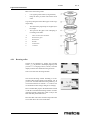
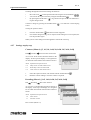
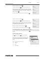
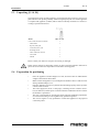
Open the water tap and check if the swivel connections are not leaking.
Put the cable with inlet plug into the back of the container and insert the plug into
the socket of the flow water heater (fig. 1-1).
Check if the containers are positioned correctly, with a filter unit (still without coffee), and position the swivel arm above the centre of the filter.
Switch the appliance on by putting the ON/OFF switch (fig. 1-2) in position I, the
display (fig. 1-5.2)lights up and you will hear a beeping sound. Then the display
will indicate the standard choices.
Press selection button 2 (fig. 1-5.4) and confirm your choice by pressing the
START button (fig. 1-5.7). The coffee system starts filling and the brewing process starts. In the display appears the text: BREWING. With the STOP button
(fig.1-5.1) the brewing process can be interrupted at any moment. When the watersupply stops coming out of the swivel arm, you will hear a beeping sound (1x
short). In the display appears the text: LEAKING. The leaking time is set as standard to approx. 5 minutes, and its ending is indicated by a beeping sound (3x short).
Empty the container with the drainage tap (fig. 1-15).
Position the swivel arm above the other filter and follow the above procedure once
again if the model is equipped with two containers.
Once the container is empty the coffee maker is ready for use.
13
13.2.2006
Rev. 2.2
Operation instructions
4.1.2
First settings operator menu
The following details are set in the operator menu immediately after being used for the
first time. Please note: The default language setting is English. To gain access to the operator menu system settings see chapter “The operator menu”.
System settings (Systeminstellungen) (menu 2)
2.0
Language
2.1
Time
2.2
Date
Coffee settings (menu 3)
4.2
3.9
Descale indicator
3.10
Coffee dosing
Operation procedures
This chapter describes the daily use of the appliance by partly qualified personnel. When
the machine is used for the first time, it works in accordance with the standard factory settings. The different settings can be changed later by trained, qualified personnel. See “The
operator menu” for more details.
Inspect the appliance before using it and check it for damage.
Never submerge or spray the appliance.
Do not press the buttons with a sharp object.
Protect the controls against dirt and grease.
During use some parts will become very hot.
Do not position the container on open fire or on a hotplate.
First disconnect the electric cable before transporting the container.
It is advisable to take the plug out of the socket and close the water tap if the appliance is
not going to be used for longer periods of time.
Preparations
•
•
•
14
Put the cables with inlet plug into the back of the container and insert the plug into
the socket of the flow water heater (fig. 1-1).
The inner pot of the container must always be fresh and clean.
Place the coffee blender into the container. The blender guarantees a uniform quality of the coffee, which makes stirring the coffee (with loss of time, temperature
and aroma) unnecessary. The temperature of the coffee is kept at a temperature of
80-85°C. The storage time of the coffee is determined by the blend of coffee and
is usually 1 à 1,5 hours.
13.2.2006
Rev. 2.2
Operation instructions
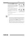
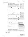
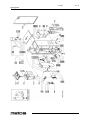
Basic rules for brewing coffee
•
•
Use regular ground coffee (±50 gram/liter)
Keep the inner pot, filter unit and the mixer
clean.
Tip: always keep the basket filter paper in the original packing!
•
•
4.2.1
This means the paper keeps its original (basket) shape.
This prevents the paper from collapsing or
not fitting in the filter.
A
Filter lid with water distributor
B
Basket filter paper
C
Basket filter
D
Blender
E
Insulated lid
F
Container
Brewing coffee
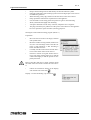
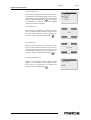
Switch on the appliance by putting the ON/OFF
switch (
) in position I, the display lights up and
you will hear a beeping sound (1x short). Then the
display indicates the standard brewing amounts.
Select one of the four brewing amounts.
The selected brewing amount including a recommended coffee dosage appears in the display. Tip: If
you do not want the selected brewing amount, you
can increase/decrease it with the + or - button. The
recommended coffee dosage changes accordingly.
Place a basket filter paper in the basket filter and fill
it with the recommended brewing amount of coffee
(standard ground). Spread the coffee evenly in the
filter and then put the filter lid on.
Place the filter unit on the container and position the
swivel arm above the centre of the filter.
15
13.2.2006
Rev. 2.2
Operation instructions
Press the START button (
) to start the brewing
process. In the display appears the text: Processing.
The container heating switches on automatically,
the heating should be switched off manually (
)
if the container is empty. During the coffee brewing
process, the display shows the selected brewing
amount (below) and the amount of water already
gone through the filter (above).
When the water supply stops coming out of the
swivel arm you will hear a beeping sound (1x
short). In the display appears the text: Leaking out.
The leak out time is set as standard to approx. 5
minutes, and its ending is indicated by a beeping
sound (3x short).
Remove the synthetic filter after it has been used
and put the insulated lid on the container.
Clean the synthetic filter.
After the brewing process you can draw off a cup of coffee by using the no-drip tap on the
container.
Tip
•
•
•
16
If the swivel arm and/or the container are moved out of position before and/or during the brewing process, the brewing process will stop, a swivel arm and/or container symbol will appear in the display and you will hear a beeping signal (2x
short). Once the positioning fault has been resolved the brewing process can be restored by pressing the START button (
) . See “Error reporting symbols”.
The brewing process can be interrupted at any moment with the STOP button
(
). The brewing process should then be considered as lost.
Prepare another brewing process by getting the second synthetic filter ready if required. Once the water supply has stopped coming from the swivel arm, you canposition the swivel arm above the other filter and start a new brewing process
immediately. The dripping symbol from the 1st container will then disappear.
13.2.2006
Rev. 2.2
Operation instructions
4.2.2
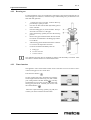
Brewing tea
For the preparation of tea you can follow the same steps as the ones described for the coffee brewing process. However, instead of using a coffee making unit, you should use a tea
filter and disk (optional).
1.
2.
3.
4.
5.
6.
7.
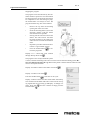
1. Put the tea, loose or in bags, in the tea filter approximately 6 grams per liter.
nsert the tea filter into the disk (B) already placed
in the container.
Place the filling pipe (A) on the tea filter. Then position the swivel arm over the pipe.
Select the brewing quantity and start the brewing
process.
Remove the pipe and the tea filter after the tea has
been made. ATTENTION: the filling pipe and filter are HOT!
After brewing put the insulated lid on the container
to avoid loss of temperature and taste.
Clean the tea filter immediately after use.
A
Filling pipe
B
Tea filter with disk
C
Container with lid
The optimum extraction time is minimally 4 minutes and maximally 15 minutes. After
more than 15 minutes the flavor of the tea deteriorates.
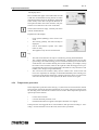
4.2.3
Timer function
The appliance comes with a built-in timer clock as standard. You can use this to start a
coffee brewing process at a certain time.
Press the timer button (
).
Set the required start time (day/hour/min) with the
left and right selection buttons (fig. 9A) and confirm
your setting with the START button(
). The day
automatically moves to the next day when the hour
setting goes past 24:00. Confirm your choice with
the START button (
)
Select the required brewing quantity (fig. 9B) and
confirm your choice with the START button
17
13.2.2006
Rev. 2.2
Operation instructions
The display shows.
Place a basket filter paper in the basket filter and fill
it with the recommended brewing amount of coffee
(standard ground) as shown in the display. Spread the
coffee evenly in the filter and put the filter lid on.
Then place the filter unit on the container, and position the swivel arm above the centre of the filter.
Check if the container is empty. Confirm your choice
with the START button .
Explanation of the display:
•
•
•
•
Clock symbol (flashing): timer clock is activated
The brewing quantity, start time and day are
displayed.
Swivel arm/container symbol: The coffee
maker is ready.
The appliance may NOT be switched off!
Tip
•
•
•
4.2.4
The timer clock function can only be cancelled by pressing the STOP button .
The container heating switches on automatically 5 minutes before the set time
(pre-heating). The coffee brewing process is switched off during an activated timer
clock function. The container heating can be used normally, for example, to keep
the coffee on the left warm, while on the right the coffee brewing process is preprogrammed.The timer can be programmed a maximum of 6 days inadvance. This
enables you to bridge a long weekendeasily.
The swivel arm and container safety devices remain active. If the swivel arm
moves out of position, for example, it is detected immediately and a warning symbol appears in the display followed by a beeping sound (2x short). Once the swivel
arm is moved back to the correct position, the timer clock is active again.
Temperature protection
There temperature protection in the unit (fig. 1-6) that can be accessed from the outside.
The protection switch off when the temperatures rise too high. The most common cause
for switching off is scale that has not been removed in time. If the temperature protection
operates proceed as follows:
•
•
•
Let the unit cool down.
Unscrew the black protection cover.
Push the button that now appears and replace the black cover tightly.
If the protection was triggered due to scale formation, then proceed according to “Descaling”. If scale formation was not the cause, then contact your dealer.
18
13.2.2006
Rev. 2.2
Operation instructions
4.2.5
The operator menu [5, 1x5, 10, 1x10, 20, 1x20, 2x5, 2x10, 2x20]
This chapter describes how the different settings
can be changed by trained, qualified personnel. To
gain access to the operator menu, read below.
Once in the operator menu the control panel has
the following functions:
4.2.6
Button
selection arrow
up
Button
selection arrow
down
Button
back (without saving changes)
Button
accept (activate)
Menu functions
You have the possibility of changing settings and have access to a number of maintenance
functions via the operator menu. It is possible to select the following functions:
Menu Explanation of Operator menu
0
Counters
1
Descaling
2
System settings
3
Coffee settings
4
Load defaults
5
Load defaults [W]
Getting access to the operator menu
1.
2.
3.
4.
5.
6.
Switch the appliance off (0)
Hold the START button (
) and switch on
(I) the ON / OFF switch (
).
Release the START button when the display
lights up. In the display appears: Operator
menu. Press any button
Press any button. In the display appears: Enter PIN: _ _ _ _ _
Look up the associated 5 digit PIN and enter
it using the numbered buttons in the display
(5.3 to 5.6). Please note: the code number is
produced at random, so the PIN is always
different!
After entering the PIN the Operator menu
will light up in the display.
19
13.2.2006
Rev. 2.2
Operation instructions
Scrolling through the menu and activating the functions
•
•
•
Move the arrow
to the required menu item using the selection buttons
You activate the required menu by using the START button
.
By pressing the STOP button
you go back to the previous screen without saving the changes made.
Confirm a change by pressing the START button
sound.
. You will hear a short beeping
Closing the operators menu:
1.
2.
Press the STOP button
until the user menu reappears.
Check if the changed settings are as required. If the settings are not as required,follow the procedure again.
While you are in the settings menu the appliance will not fill or heat up
4.2.7
Settings step by step
Counters (Menu 0) [5, 1x5, 10, 1x10, 20, 1x20, 2x5, 2x10, 2x20]
PIN
Counters
then select the counter item
An overview of all counter functions follows in the
display. At the top of the display is a navigation bar
on which the selected menu item number is shown.
Menu Explanation of Operator menu
0.0
Daily counter of coffee made in litres
0.1
Reset daily counter of coffee made
0.2
Total counter of coffee made in litres
1.
2.
Select the required counter, and confirm with the START button
Read the counter reading or reset the counter as required.
Descaling (Menu 1) [1x5, 1x10, 1x20, 2x5, 2x10, 2x20]
PIN
Descaling
then select function
An overview of all descaling functions follows in
the display. At the top of the display is a navigation
bar on which the selected menu function number is
shown.
Menu Explanation of Operator menu
1.0
Flow counter
1.1
Start flow counter
Flow counter (Menu 1.0)
20
.
13.2.2006
Rev. 2.2
Operation instructions
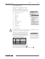
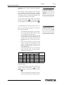
After activating the flow counter you can read how many litres away from a descaling signal the coffee maker is. Example: The diagram opposite indicates that the coffee making
part (flow system) is still 961 litres away from a descaling signal. The counters are automatically reset after the relevant descaling program has been run.
Warnings
•
•
•
•
•
•
•
•
Respect the descaling intervals indicated by the descale indicator symbol.
Delaying maintenance of the heating system can lead to high repair costs and can
invalidate the guarantee.
When descaling, always pay attention to the directions on the scale remover.
Keep up with the maintenance requirements for the appliance
It is advisable to wear safety glasses and protective gloves when descaling.
Wash your hands thoroughly after descaling.
All repairs should be carried out by a trained, competent service engineer.
The plug must always be pulled out of the power socket whenever the appliance
has to be opened for repairs and other (cleaning) purposes.
Starting the coffee maker descaling program (Menu 1.1)
Preparation
•
•
•
•
Move the swivel arm above an empty container
and synthetic filter.
Brew the smalles brewing amount (without coffee) once. The advantage of this is that the element is well preheated, so that descaling is
better and takes less time.
Carefully read the caution notice and the directions on the sachet Animo scale remover.
Dissolve 2 sachets of 50 gram Animo scale remover into 2 litre of warm water (60°C). Stir the
solution thoroughly so that the powder is completely dissolved.
Remove the filter and place a plastic container under
the outlet of the swivel arm to collect the scale remover.
•
Follow the instructions shown on the display
and confirm each action with
.
Display: 1/5 Place measuring cup. Press start
.
21
13.2.2006
Rev. 2.2
Operation instructions
Stopping the program
The program can be cancelled at any time until the solution is poured in. Once the solution
has been poured in, the program must always
be completed. In case of an emergency stop,
the STOP button can always be used. The
program will then stop, but not be finished.
•
•
•
•
•
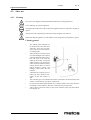
Remove the cap from the descaling
opening left of the swivel arm.
Insert the descaling funnel (A) into the
descaling opening. Push the funnel
downward as far as possible.
Slowly pour the scale remover into the
funnel. The scale remover will enter
the boiler element by the supply pipe
and will come out of the swivel arm as
foam.
Repeat the procedure described above
if there is a grat amount of foam.
Press the START button
to continue the programm.
Display: 2/5 <- funnel left. Pour solution
through. Ready? Press start
.
The program is now ready to flush the system
3 times, so that the remaining scale remover can be removed from the heating system. Remove the funnel and replace the cap
. . Remove the plastic container with the collected scale
remover and replace the filter.
Display: 2/5 Remove funnel. Place filter. Press Start
Display: 3/5 Rinse. Press Start
Press the START button
.
to start the 1st rins cycle.
Display: 3/5 Rinse. Please wait.The coffee maker will heat up.
The container will be filled with 2 litres. There will be 3 beeping signals after the 1st rinsing cycleDisplay: 3/5 Empty container. Press Start
.Once the container is empty press the
START button
.
22
13.2.2006
Rev. 2.2
Operation instructions
Display: 4/5 Rinse. Press Start
Press the START button
.
to start the 2nd rinsing cycle.
Display: 4/5 Rinse. Please wait.The coffee maker will heat up.
The container will be filled with 2 litres. There will be 2 beeping signals after the 2nd rinsing cycle.Display: 4/5 Empty container. Press Start
.
Once the container is empty press the START button
Display: 5/5 Rinse. Press Start
Press the START button
.
.
to start the 3rd rinsing cycle.
Display: 5/5 Rinse. Please wait.The coffee maker will heat up.
The container will be filled with 2 litres. There will be 3 beeping signals after the 3rd rinsing cycle.
Display: 5/5 Empty container. Press Start
.
Once the container is empty press the START button
.
The descaling program is now complete and the descaling
menu will reappear in the display. The flow counter will automatically be reset to the starting value. Exit the menu by pressing the STOP button
twice, or select another menu
function.
Descaling (Menu 1) [5, 10, 20]
PIN
Descaling
then select function
An overview of all descaling functions follows in
the display. At the top of the display is a navigation
bar on which the selected menu function number is
shown.
Menu Explanation of Operator menu
1.0
Flow counter
1.1
Start flow counter
Flow counter (Menu 1.0)
After activating the flow counter you can read how
many litres away from a descaling signal the coffee maker is. Example: The diagram opposite indicates that the coffee making part (flow system) is still 961 litres away from a
descaling signal. The counters are automatically reset after the relevant descaling program
has been run.
Warnings
23
13.2.2006
Rev. 2.2
Operation instructions
•
•
•
•
•
•
•
•
Respect the descaling intervals indicated by the descale indicator symbol.
Delaying maintenance of the heating system can lead to high repair costs and can
invalidate the guarantee.
When descaling, always pay attention to the directions on the scale remover.
Keep up with the maintenance requirements for the appliance
It is advisable to wear safety glasses and protective gloves when descaling.
Wash your hands thoroughly after descaling.
All repairs should be carried out by a trained, competent service engineer.
The plug must always be pulled out of the power socket whenever the appliance
has to be opened for repairs and other (cleaning) purposes.
Starting the coffee maker descaling program (Menu 1.1)
Preparation
•
•
•
•
Move the swivel arm above an empty container
and synthetic filter.
Brew the smalles brewing amount (without coffee) once. The advantage of this is that the element is well preheated, so that descaling is
better and takes less time.
Carefully read the caution notice and the directions on the sachet Animo scale remover.
Dissolve 2 sachets of 50 gram Animo scale remover into 2 litre of warm water (60°C). Stir the
solution thoroughly so that the powder is completely dissolved.
Remove the filter and place a plastic container under
the outlet of the swivel arm to collect the scale remover.
•
Follow the instructions shown on the display
and confirm each action with
.
Display: 1/5 Place measuring cup. Press start
24
.
13.2.2006
Rev. 2.2
Operation instructions
Stopping the program
The program can be cancelled at any time until the solution is poured in. Once the solution
has been poured in, the program must always
be completed. In case of an emergency stop,
the STOP button can always be used. The
program will then stop, but not be finished.
•
•
•
•
•
Remove the cap from the descaling
opening left of the swivel arm.
Insert the descaling funnel (A) into the
descaling opening. Push the funnel
downward as far as possible.
Slowly pour the scale remover into the
funnel. The scale remover will enter
the boiler element by the supply pipe
and will come out of the swivel arm as
foam.
Repeat the procedure described above
if there is a grat amount of foam.
Press the START button
to continue the programm.
Display: 2/5 <- funnel left. Pour solution
through. Ready? Press start
.
The program is now ready to flush the system
3 times, so that the remaining scale remover can be removed from the heating system. Remove the funnel and replace the cap . Remove the plastic container with the collected scale
remover and replace the filter.
Display: 2/5 Remove funnel. Place filter. Press Start
Display: 3/5 Rinse. Press Start
Press the START button
.
to start the 1st rins cycle.
Display: 3/5 Rinse. Please wait.The coffee maker will heat up.
The container will be filled with 2 litres. There will be 3 beeping signals after the 1st rinsing cycleDisplay: 3/5 Empty container. Press Start
.Once the container is empty press the
START button
.
25
13.2.2006
Rev. 2.2
Operation instructions
Display: 4/5 Rinse. Press Start
Press the START button
.
to start the 2nd rinsing cycle.
Display: 4/5 Rinse. Please wait.The coffee maker will heat up.
The container will be filled with 2 litres. There will be 2 beeping signals after the 2nd rinsing cycle.Display: 4/5 Empty container. Press Start
.
Once the container is empty press the START button
Display: 5/5 Rinse. Press Start
Press the START button
.
.
to start the 3rd rinsing cycle.
Display: 5/5 Rinse. Please wait.The coffee maker will heat up.
The container will be filled with 2 litres. There will be 3 beeping signals after the 3rd rinsing cycle.
Display: 5/5 Empty container. Press Start
.
Once the container is empty press the START button
.
The descaling program is now complete and the descaling
menu will reappear in the display. The flow counter will automatically be reset to the starting value. Exit the menu by pressing the STOP button
twice, or select another menu
function.
System settings (menu 2)
PIN
System settings
then select function
An overview of all system settings follows in the
display. At the top of the display is a navigation bar
on which the selected menu function number is
shown.
Menu Explanation of Operator menu
26
2.0
Language
2.1
Time
2.2
Date
2.3
Sound signal
13.2.2006
Rev. 2.2
Operation instructions
Language (Menu 2.0)
Before using the appliance you must first set the desired language. The default language setting is English. Select the required language, and confirm your
changes with the START button
. Tip!: If Menu
4-Load defaults is activated, the altered language
choices will remain unchanged.
Time (Menu 2.1)
Before using the appliance you must first set the
time. Use the left selection button to set the hour Use
the right selection button to set the minutes. Confirm your changes with the START button
.
Date (Menu 2.2)
Before using the appliance you must first set the
date. Use the left selection button to set the day Use
the right selection button to set the month. The year
count changes automatically every 12 months. Confirm your changes with the START button
.
Sound signal (Menu 2.3)
When in use the appliance makes different sound
signals. You can switch the sound signals off if desired. Select the required choice and confirm your
changes with the START button
.
27
13.2.2006
Rev. 2.2
Operation instructions
Coffee settings (Menu 3)
PIN
Coffee settings
then select function
An overview of all coffee settings follows in the display. At the top of the display is a navigation bar on
which the selected menu function number is shown.
Menu Explanation of Operator menu
3.0
Water volume
3.1
Unit
3.2
Cup volume
3.3
Mug volume
3.4
Button 1
3.5
Button 2
3.6
Button 3
3.7
Button 4
3.8
Auto container heating
3.9
Descale indicator
3.10
Coffee dosage
3.11
Interval
3.12
1st charge volume
3.13
Leak out time
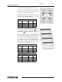
Water volume (Menu 3.0)
The container will overflow if too large an amount is set. The manufacturer accepts no
responsibility for the consequences of changed settings.
During use, it can occur that the quantity of water in
the container is not as required. This depends on the
amount of coffee and the size of coffee ground used.
The amount of water that comes out of the swivel
arm is set to 6% - 10% extra water as standard. The
table below shows the settings scope.
Water volume
Model
Factory settings
Settings
CB 5W
5,300 ml
4,800-5,800 ml
CB 10W 10,800 ml
9,800-11,800 ml
CB 20W 22.000 ml
20.000-24.000 ml
Increase or decrease the water volume [ml] with the
selection buttons above and below the display. Confirm the changes made with START button
or
go back without making any changes by pressing the STOP button
28
.
13.2.2006
Rev. 2.2
Operation instructions
Unit (Menu 3.1)
You can change the unit in which the selection buttons are shown in the display with this function.The
unit can be set as Litres (standard), Jug or Cup.
Select the required unit and confirm your changes
with the START
button or go back without saving any changes using the STOP button
.
Please note: The counter menu continues to be displayed in litres.
Cup volume (Menu 3.2)
You can change the volume of the cup with this
function. The cup volume is set to 125 ml as standard The settings scope is between 100 and 500 ml (1
ml steps).
Set the required cup volume and confirm your
changes with the START button
or go back
without saving any changes by pressing the STOP
button
.
Jug volume (Menu 3.3)
You can change the volume of the jug with this
function. The jug volume is set to 250 ml as standard
The settings scope is between 200 and 2500 ml (1
ml steps).
Set the required jug volume and confirm your
changes with the START button
or go back
without saving any changes by pressing the STOP
button
.
29
13.2.2006
Operation instructions
Changing the selection buttons (Menu 3.4 to 3.7)
You can set each selection button as required with
this function. The four selection buttons are set in
the factory as shown in the table below .
With the help of Buttons 1 to 4 (menu 3.4 to 3.7), the
choice can be set within the scope with associated
step size indicated in the table below.
Selection buttons unit litres
Model
Factory settings Settings
scope
CB 5W
1-3-4-5 l
Step
1-5 l
0,5 l
CB 10W 2,5-5-7,5-10 l
2-10 l
0,5 l
CB 20W 5-10-20-40 l
4-20 l
1l
Set the required amount for button 1 and confirm
your changes with the START button
or go
back without saving any changes by pressing the
STOP button
. Repeat this for buttons 2 to 4.
Have you changed the unit of Litres to Cup or Jug?
The litre setting is automatically calculated by the
relevant litre setting divided by the cup or jug volume. The four selection buttons then automatically
have the settings as shown in the following overview (Table 3 + 4) Each selection button within the
settings scope and associated step size can be set
with the help of the menu buttons 3.4 to 3.7.
Selection buttons unit cups
Model
Factory settings Settings
scope
Step
CB 5W
8-24-32-40
1 cup
CB 10W 20-40-60-80
8- 4 cups
20-80 cups 1 cup
CB 20W 40-80-120-160 8- 4 cups
5 cups
Selection buttons unit jugs
30
Model
Factory settings Settings
scope
Step
CB 5W
4-12-16-20
1 jug
4-20 jugs
CB 10W 10-20-30-10
10-40 jugs 1 jug
CB 20W 20-40-60-80
20-80 jugs 1 jug
Rev. 2.2
13.2.2006
Rev. 2.2
Operation instructions
Switching on the container heating automatically
(menu 3.8)
When starting a coffee making process the appliance automatically switches the right container
heating on. The container heater then stays switched
on and must always be switched off manually. You
can switch this function off if required.
Set the required choise and confirm your changes
with the START button
or go back without saving any changes by pressing the STOP button
.
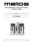
Coffee making descale indicator settings (menu 3.9)
Before you start using the appliance you must first
set the descale indicator.
•
•
•
•
The default descale indicator is set to 1000 litres (average water hardness) and has a scope
of 0 to 9999 litres in steps of 100
Use the table 5 below and select the relevant
water hardness in the left column (°D). On
the right you can read after how many litres
(recommended) the system must be descaled.
Once the set amount of litres has been
reached a spanner symbol will appear in the
display. The appliance will continue to work
normally so that descaling can be done at a
more suitable time.
In the Descaling menu 1.0 you can see how
many litres away from a descale indicator
signal the system still is.
Water
quality
Hardness
ºD
ºF
mmol/l
mgCaCo3/l
Descale indicator litres
Very hard
18-30
32-55
3,2-5,3
321-536
250
Hard
12-18
22-32
2,2-3,2
214-321
500
Average
8-12
15-22
1,4-2,2
268-214
1000*
Soft
4-8
7-15
0,7-1,4
72-268
1500
Very soft
0-4
0-7
0-0,7
0-72
2000
*Standard setting
Set the required number of litres and confirm your
changes with the START button
or go back
without saving any changes by pressing the STOP
button
.
•
Contact your local water company if you are
unsure about the hardness of your tap-water.
31
13.2.2006
Rev. 2.2
Operation instructions
Coffee dosage (menu 3.10)
When an amount is selected, the recommended
amount of ground coffee (grams) that should be put
in the filter unit in order to make the selected
amount of coffee appears in the display.The amount
of coffee is set to 50 grams/litre as standard and can
be set from 0 to 100 grams in steps of 1 gram.
Set coffee dosage and confirm your changes with
the START button
or go back without saving
any changes by pressing the STOP button
.
If the coffee dosage advice is not desired you can switch it off by setting the grams/litre
value to 0.
Please note: When setting larger amounts of coffee a negative correction factor is applied
to the calculation. This means that the coffee dosage advice is lower than the result of the
calculation 'brewing quantity x coffee dosage.
Interval (menu 3.11)
Using very finely ground coffee or very soft water
will result in the water running through the coffee
filter more slowly. Pausing the hot water pouring after the 1st charge volume (half way through the
making process) for periodic intervals (that can be
set) can prevent the coffee filter from overflowing.
Interval Settings
•
•
•
•
32
The interval is set to 100% as standard. The
brewing process can then run smoothly.
The interval can be set from 100% to 50% in
steps of 5%. After a setting has been made
the controller calculates the time out interval
itself (see table below).
If the hot water pouring switches to the interval mode after the 1st charge, the water supply and pausing will continue until the
required volume has been reached.
The interval setting and the 1st charge volume can only be determined by trial and error by keeping an eye on the filtering process
during the coffee making.
13.2.2006
Rev. 2.2
Operation instructions
Set the required number of litres and confirm your changes with the START button
or go back without saving any changes by pressing the STOP button
.
Interval Water pourng Intervaltime
time
100%
Continue
0 sec
95%
45 sec
4,5 sec
90%
45 sec
9 sec
85%
45 sec
13,5 sec
80%
45 sec
18 sec
75%
45 sec
22,5 sec
70%
45 sec
27 sec
65%
45 sec
31,5 sec
60%
45 sec
36 sec
55%
45 sec
40,5 sec
50%
45 sec
45 sec
1st charge menu (menu 3.12)
The 1st charge volume can be increased if it is only
found outlater in practise that the filtering process
threatens to overflow
Setting the 1st charge volume
•
•
•
The 1st charge volume only becomes active
if the interval is set at 95% or less.
The 1st charge volume is set for half way
through the brewing process as standard.
The 1st charge volume can be set according
to the table below.
Set the desired 1st charge volume and confirm your
changes with the START button
or go back
without saving any changes by pressing the STOP
button
.
Model
Factory settings Settings scope
Step
CB 5W
2.500 ml
2500-4500 ml
250
CB 10W 5.000 ml
5000-9000 ml
250
CB 20W 10.000 ml
8000-18000 ml
250
33
13.2.2006
Rev. 2.2
Operation instructions
Leak out time (menu 3.13)
The leak out time starts once the hot water distribution is stopped. The leak out time through the filter
can vary depending on the type, size and/or amount
of coffee.
Leak out time settings
•
If no leak out time is required the time can be
set to 0. There will then be no dripping symbol in the display followed by a sound signal..
Set the required leak out time and confirm your
changes with the START button
or go back
without saving any changes by pressing the STOP
button
.
Model
Factory settings Settings scope
CB 5W
Step
240 sec
0-900
10
CB 10W 300 sec
0-900
10
CB 20W 360 sec
0-900
10
Load defaults (menu 4) [5, 1x5, 10, 1x10, 20, 1x20, 2x5, 2x10, 2x20]
You can restore all the default settings except for the
language setting with this function. Please note: All
settings that you have changed in the operator menu
will be lost.
Press the START button
to load the default settings or go back without making any changes by
pressing the STOP
button .
34
13.2.2006
Rev. 2.2
Operation instructions
4.3
After use
4.3.1
Cleaning
Do not leave the appliance unattended when maintenance is being performed
Never submerge or spray the appliance
The plug must be taken out of the socket if the appliance has to be opened for cleaning or
repairs
Always follow the manufacturer instructions when using the scale remover.
When descaling the appliance, it is advisable to wear safety glasses and protective gloves.
Cleaning general
•
•
•
•
•
•
The outside of the container can
be cleaned with a wet cloth, then
wiped dry. Never use any abrasives, as these can cause scratches and dull spots.
Always take the connection lead
out of the multiple socket during
cleaning and maintenance activities and close it off with the
splash protector (B). An opened
splash protector (A) protects the
socket connection from moisture
running in from above. A closed
splash protector protects the
multiple socket from dirt and
moisture.
Attention! Do not place the container type CNe (electrical execution) in the dish washer or
sink.
The container type CNi (insulated execution) is allowed to be cleaned in the dish
washer or sink, because of its IP 65 construction.
Do not leave the filter and the blender on a container which is not in use. Place the
lid obilique on the container, otherwise a stale taste may be the result.
Always leave some clean water (2 cups) in the container, This stops the washers
from drying out.
35
13.2.2006
Rev. 2.2
Operation instructions
Cleaning daily
•
•
•
Rinse the inner pot of the container after use with hot water, or use if necessary
Animo coffee fur remover. Empty the container with the no-drip tap.
The filter, water distributor lid, blender and drip tray can be washed normally and
rinsed clean. The filter andwater distributor lid are allowed to be cleaned in the
dishwasher.
Despite daily cleaning coffee deposits can still remain in the inner pot and the
gauge glass, see chapter “Cleaning wekly”, “Cleaning the tap” and “Cleaning the
gauge glass”.
Cleaning weekly
A sachet of coffee fur remover is supplied with the machine. Use is extremely simple.
Removal of coffee deposits from the inner pot:
1.
2.
3.
Fill half of the container with warm water and dissolvea sachet of coffee fur remover in it.
Let the solution work for 15 to 30 minutes, then empty the container.
Rinse the container thoroughly with hot water a few times.
Removal of coffee deposits from the other parts:
1.
2.
3.
4.
Take a bowl filled with abt. 5 liter warm water and dissolve the coffee fur remover
solvent from the sachet in it.
Put the parts that need to be cleaned in the bowl and soak them for 15 to 30 minutes.
Rinse several times with warm water. Repeat treatment if the result is insufficient.
Scatter coffee fur remover on very filthy spots and clean with a wet brush.
Cleaning the tap
1.
2.
3.
4.
36
Unscrew the top of the tap by turning it to
the left.
Pull the silicon sealer vertically away from
the screw top
Put the parts to be cleaned in this solution
and let it work for 15 to 30 minutes.
Then rinse off several times with warm water and put back together in reverse order,
repeat if the results are insufficient.
13.2.2006
Rev. 2.2
Operation instructions
Cleaning the gauge glass
Risk of burning! Empty the container before you remove the gauge glass for cleaning.
Always treat the gauge glass with the necessary caution. Take the glass out of the protector with the help of a dry cloth and hold the gauge glass firmly with the cloth as you clean
it with the gauge glass brush.
1.
2.
3.
4.
5.
6.
Empty the container, remove the filter and the
coffee blender.
Take the gauge glass lid (A) off by pulling it
vertically up from the protector profile.
Take a dry cloth, and use it to take the top of the
gauge glass (C) from the recess and pull the
gauge glass carefully diagonally up out of and
loose from the tap connection.
Remove the bottom tulle (F) from the gauge
glass and clean the gauge glass with the help of
the supplied gauge glass brush. (careful fragile!)
Moisten the gauge glass ends + tulle and put the
tulle back in the glass and push the gauge glass
into the tap connection with the tulle (G).
Always put the gauge glass lid (A) vertically on
the protector profile, push the top tulle with the
index finger (in the middle of the gauge glass
lid). Please note: make sure that the gauge glass
lid stays firmly pushed against the container
wall when placing it. Only then the gauge glass
will stay well. (The lip in the gauge glass lid (A)
must be behind the holding plate (B).
A - Gauge glass lid
B - Holding plate
C - Gauge glass
D - Extra gauge glass
E - Protector profile
F - Lower tulle
G - Tap cap
On the inside of the gauge glass protector is a spare gauge glass (D). The assembly of the
gauge glass system is much easier if you moisten the gauge glass ends and tulles well.
4.3.2
Periodic descaling activities
This chapter describes the periodic descaling activities of the machine that can only be executed by trained, qualified personnel.
Observe the descaling intervals indicated by the descaling indicator symbol.
Overdue maintenance to the heating system can result in high repair costs and annulment
of the guarantee.
37
13.2.2006
Rev. 2.2
Operation instructions
Always follow the manufacturer instructions when using the scale remover.
Do not leave the appliance unattended when maintenance is being performed.
When descaling the appliance, it is advisable to wear safety glasses and protective gloves.
Wash your hands after descaling.
Descaling the coffee maker
After entering the Operator PIN you have access to the descaling menu where you can
start the descaling program for the coffee maker. Follow the descaling procedure as described in the operator menu.
38
13.2.2006
Rev. 2.2
Installation
5. Installation
5.1
General
This appliance may only be positioned and connected by a qualified service engineer. The
following rules must be observed:
•
•
•
only suitable for indoor use
not suitable for use in humid areas
not suitable for areas with explosion hazard
39
13.2.2006
Rev. 2.2
Installation
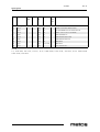
5.2
Unpacking [1x5, 1x10, 1x20, 2x5, 2x10, 2x20]
The machine has been carefully packed to prevent damage being caused to your new appliance.
Remove the packing carefully without using sharp objects. Check if the appliance is complete.
The appliance (tower) will be delivered already mounted on a base plate according to the
specifications below.
Model
CB 2x_
CB 1x_L
CB 1x_R
- 1 swivel arm
1
1
1
- 1 drip tray with grid
1
1
1
Carton with basket filter
2
1
1
2
1
1
1
1
1
- 1 sythetic filter
- 1 water distributor lid
- 1 set basket filter paper abt. 25 pcs
Carton with container
- 1 container
- 1 insulated lid
- 1 blender/transport disk
- 1 gague glass brush
- 1 sticker sheet coffee/tea
- 1 electric cable 1,5m
Carton with accessories column/base
- 1 connection hose 1,5m
- 1 descaling funnel
- 1 sachet coffee fur remover
- 1 sachet scale remover
- 1 manual
- 1 set centric shoulders (4x)
- 2 electric cables 0,6m
Please contact your dealer in case parts are missing or damaged.
Water always remains in the heating system: for this reason the appliance must not be
placed in an area where the temperature can fall below freezing point.
40
13.2.2006
Rev. 2.2
Installation
5.3
Unpacking [5, 10, 20]
The machine has been carefully packed to prevent damage being caused to your new appliance.Remove the packing carefully without using sharp objects. Check if the appliance
is complete.The appliance (column) will be delivered already mounted on a console according to specifications below.
Model
CB 5 / 10 / 20
Carton with accessories column:
1
- wall bracket
1
- drip tray with grid
- connection hose 1,5m
1
- descaling funnel
1
- sachet coffee fur remover
1
- swivel arm
1
- manual
1
Please contact your dealer in case parts are missing or damaged.
Water always remains in the heating system: for this reason the appliance must not be
placed in an area where the temperature can fall below freezing point.
5.4
Preparation for positioning
•
•
•
•
•
•
Place the appliance at buffet height on a firm, level base that can withstand the
weight of the machine when filled.
Make sure that the appliance is level and placed somewhere where it will not cause
damage should leakage occur.
Place the appliance in such a way that the descaler filling opening on the top of the
column can be reached.
The water supply line (G3/4" 15 mm pipe), a discharge for the overflow connection (25 mm hose) and the power connection must be within half a meter of where
the machine is positioned.
The user is responsible for ensuring that these technical installation preparations
are executed according to local regulations by qualified engineers.
The service engineer is only permitted to connect the appliance to the prepared
connection points.
41
13.2.2006
Rev. 2.2
Installation
5.5
Water connection
Connect the appliance using the water hose to an easily accessible aeration tap that can be
closed quickly if problems arise. The minimum water pressure may not be under 0,2 Bar
(at 5L/min. flow pressure)
The appliance can only be connected to a cold water outlet.
5.5.1
Water treatment
You are emphatically advised to use a water softener and/or a water filter if the water contains too much chlorine or is too hard (>8°dH). This enhances the quality of the drink and
precludes having to descale the appliance too often.
5.6
Water drainage
Tha appliance doesn’t need to be drained.
42
13.2.2006
Rev. 2.2
Installation
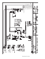
5.7
Electrical connection
Supply voltages and frequencies can differ between countries. Check if the appliance is
suitable for connection to the local power mains. Check if the details on the type plate correspond.
The earthed wall socket and the fused group with a main switch belong to the electrical
installation. No heavy machines that could cause variations in power when being switched
on, can be connected to this group. A machine with power current (three phase) is delivered from the factory without plug. At delivery, the machine must be provided with an
electrically suitable plug as advised and provided by the installer.
The following points should be observed when wiring a new plug:
1.
2.
3.
The green/yellow-coloured wire ("EARTH") should be connected to the terminal
which is either marked with the letter "E", the "earth" symbol ( ), or coloured
green or green/yellow.
The blue-coloured wire ("NEUTRAL") should be connected to the terminal which
is either marked with the letter "N" or coloured black.
The brown-coloured wire ("PHASE") should be connected to the terminal which
is either marked with the letter "L1, L2 and L3" or coloured red.
3N~400V(5-core cable)
3~230V (4 core cable)
1N~230V (3 core cable)
Green/Yellow Earth
(E)
Blue
(N)
Neutral
Brown
Live
(L1)
Black
Live
(L2)
Black
Live
(L3)
Green/Yellow Earth
(E)
Brown
Live
(L1)
Black
Live
(L2)
Black
Live
(L3)
Green/Yellow Earth
(E)
Blue
Neutral
(N)
Brown
Live
(L)
43
13.2.2006
Rev. 2.2
Installation
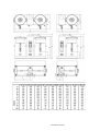
5.8
Connection on a counter [1x5, 1x10, 1x20, 2x5, 2x10, 2x20]
1.
2.
3.
4.
5.
6.
7.
8.
9.
10.
5.9
Connect the machine at counter level and on a solid flat surface.
Before the connections are made, check whether the main voltage corresponds to
the voltageindicated on the type plate.
Determine the position of the machine on the counter.
If necessary, make the transits on the counter for electricity, water and drainage,
see installation drawing for measurements.
Mount the supplied centering shoulders on the base plate.
Connect the electricity supply, cold water supply and the overflow.
Place the drip tray in front of the machine.
Place the containers against the centring shoulders, place the coffee blenders into
the containers and put the filter units on the containers.
Connect the container(s) by using the supplied short (60 cm) connection cable and
put the mains plug from the relevant column in the mains socket.
Position the swivel arm over the centre of the filter.
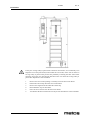
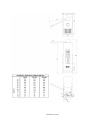
Mounting on a wall [5, 10, 20]
Mount the appliance on the wall with the aid of the bracket supplied in accordance with
the condition of the mounting wall and with the aid of suitable plugs. In case of cellular
concrete, plasterboard or similar walls of other materials screw right through them or apply extra wall reinforcement.
1.
2.
3.
4.
5.
6.
7.
44
The local voltage should correspond to the specifications indicated on the type
plate.
Determine the complete arrangement of the serving trolley(s) with flow water
heaters.
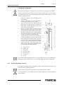
Determine position of the flow water heater, see the figure below.
Mount the flow water heater to the wall with the aid of the bracket supplied and
connect electricity, water supply and overflow pipe.
Position the serving trolley, container and filter next to the flow water heater (take
the parking rails into account see point 6), adjust the stop of the swivel arm in such
a way that the outlet is always above the centre of the filter. The stop can be
reached by pulling the swivel arm up vertically.
Take note! the swivel arm should always be at a slight downward angle.
Determine the place of the parking rails and mount them on the wall at the correct
height in such a way that the serving trolley will stand with its round push rubbers
in between the parking rails.
13.2.2006
Rev. 2.2
Installation
If only one serving trolley is placed next to the flow water heater, we recommend you to
adapt the swivel arm protection (located under the swivel arm) on the side on which no
serving trolley is placed. This prevents the possibility of starting the flow water heater
when the swivel arm is in the opposite direction to the one where the serving trolley is
placed The adaptation is done as follows.
1.
2.
3.
4.
5.
6.
Remove the swivel arm by lifting it vertically out of the flow water heater.
Detach the relevant stop from the swivel arm bottom.
Remove the magnet from the underside of this stop.
Reassemble the stop on the bottom.
Place the swivel arm back on the flow water heater.
Test whether the flow water heater can only be activated when it is above the filter.
45
13.2.2006
Rev. 2.2
Troubleshooting
6. Troubleshooting
Have all repairs to the electrical system performed by a qualified service technician.
PROBLEM
C2 (coffee)
Possible cause
Coffee maker doesn't work.Dry-boil protection
switched off.
C3 (coffee) I
Coffee maker doesn't fill any more
C3 (coffee) II
Coffee maker fills too slowly.
C4 (coffee)
C7 (coffee)
C8 (coffee)
Water inlet valve doesn't close properly.
Minimum electrode fault.
Error C3 changes to C8 after 10 minutes.The inlet valve is closed for safety.Please note: this also
happens when themax level is reached!
Problems with registering the volume ofwater.
C9 (coffee)
Measures
Reset dry-boil protection coffee making unit. Check
to see if the coffee makerneeds to be descaled, and
descale if necessary.
Check the water pressure, turn the water supply taps
completely open, check if the connecting hose is
fastened. Problem solved, error message disappears.
Check the water pressure, turn the water supply taps
completely open, check if the connecting hose is
fastened.
Call the service engineer or dealer.
Call the service engineer or dealer.
Restore water supply and restart the coffee making
process.
Call the service engineer or dealer.
If your appliance is not functioning correctly, use this troubleshooting guide to see whether you can resolve the problem yourself. If not, please contact your dealer.
46
13.2.2006
Rev. 2.2
Spare parts
7. Spare parts
General parts CB5................................ 53
Outer parts CB5 ................................... 55
Inner parts CB5 .................................... 57
General parts CB10.............................. 63
Outer parts CB10 ................................. 65
Inner parts CB10.................................. 67
General parts CB20.............................. 73
Outer parts CB20 ................................. 75
Inner parts CB20.................................. 77
Container CN5e .................................... 83
Container CN10e .................................. 85
Container CN20e .................................. 87
Container CN5i..................................... 89
Container CN10i................................... 91
Container CN20i................................... 93
47
13.2.2006
Spare parts
48
Rev. 2.2
13.2.2006
Rev. 2.2
Spare parts
Voltage
Voltage code
A
3/N/PE∼400/230V 50Hz
B
∼250V 16A 50Hz
C
3/N/PE∼380/220V 50Hz
D
3/PE∼200V 50-60Hz
F
2/PE 220−240V 50Hz
G
3/N/PE∼415/240V 50Hz
H
3/PE∼230V 50Hz
I
3/PE∼220V 60Hz
J
3/PE∼380 50Hz
K
3/PE∼400V 50Hz
L
3/PE∼415V 50Hz
M
3/PE∼440V 60Hz
N
3/PE∼460V 60Hz
O
3/PE∼480V 60Hz
P
1/N/PE~220-240V 50Hz
R
2/PE~220-230V 60Hz
S
3/N/PE∼400/230V 50Hz
T
3/PE∼230V 60Hz
U
1/N/PE~100V 50-60Hz
Product code
7.1
Voltage codes
7.2
Product codes
Full name
Model codes
CB
CB
CBW
CBW
Type codes
5
5
1x5R
1x5R
1x5L
1x5L
2x5
2x5
10
10
1x10R
1x10R
1x10L
1x10L
2x10
2x10
20
20
1x20R
1x20R
1x20L
1x20L
2x20
2x20
5W
5W
1x5WR
1x5WR
1x5WL
1x5WL
2x5W
2x5W
49
13.2.2006
Spare parts
Product code
Full name
10W
10W
1x10WR
1x10WR
1x10WL
1x10WL
2x10W
2x10W
20W
20W
1x20WR
1x20WR
1x20WL
1x20WL
2x20W
2x20W
Accessory codes
50
Rev. 2.2
13.2.2006
Rev. 2.2
Spare parts
51
13.2.2006
Spare parts
52
Rev. 2.2
13.2.2006
Rev. 2.2
Spare parts
ID
Code
SN
from
SN to Mod Type
el
Ac- Description
ces
sor
y
Module:General parts CB5
10
08165
CB
5,1x5L,1x5R,2x5
CONNECTION TUBE (BLUE)
20
99740
CB
5,1x5L,1x5R,2x5
DESCALLING FUNNEL GL/TK
30
03071
CB
5,1x5L,1x5R,2x5
CABLE
40
13141
CB
5,1x5L,1x5R,2x5
WATER DISTRIB. LID CN 5e/i CPL
CB=CB
5=5, 1x5R=1x5R, 1x5L=1x5L, 2x5=2x5, 10=10, 1x10R=1x10R, 1x10L=1x10L, 2x10=2x10, 20=20, 1x20R=1x20R,
1x20L=1x20L, 2x20=2x20
53
13.2.2006
Spare parts
54
Rev. 2.2
13.2.2006
Rev. 2.2
Spare parts
ID
Code
SN
from
SN to Mod Type
el
Ac- Description
ces
sor
y
Module:Outer parts CB5
50
07219
CB
2x5
KNOB / CENTRING SHOULDER
60
08775
CB
2x5
FOOT RUBBER ROUND 40x25 BLACK
70
02178
CB
2x5
CABLE + PLUG 3x1.5 1.5m RofH
80
03063
CB
2x5
SWITCH REED CN
90
05328
CB
2x5
WIRE PROTECTOR CLIP
100
05380
CB
2x5
WIRE PROTECTOR -M-
110
13144
CB
2x5
DRIP TRAY
120
13147
CB
1x5L,1x5R
DRIP TRAY
130
08337
CB
5
TULE 36/20 H=11.5
CB=CB
5=5, 1x5R=1x5R, 1x5L=1x5L, 2x5=2x5, 10=10, 1x10R=1x10R, 1x10L=1x10L, 2x10=2x10, 20=20, 1x20R=1x20R,
1x20L=1x20L, 2x20=2x20
55
13.2.2006
Spare parts
56
Rev. 2.2
13.2.2006
Rev. 2.2
Spare parts
ID
Code
SN
SN to Mod Type
from
el
Ac- Description
ces
sor
y
Module:Inner parts CB5
140
13177
CB
5,1x5L,1x5R,2x5
RING
150
12349
CB
5,1x5L,1x5R,2x5
-
160
03063
CB
5,1x5L,1x5R,2x5
SWITCH REED CN
170
35043
CB
5,1x5L,1x5R,2x5
TUBE SILICONE 12x8 L=350
180
08892
CB
5,1x5L,1x5R,2x5
PLUG ROUND 10
190
02088
CB
5,1x5L,1x5R,2x5
FLOWMETER CB
200
07155
CB
5,1x5L,1x5R,2x5
TUBE CLAMP 11.9 SPRINGSTEEL
210
02267
CB
5,1x5L,1x5R,2x5
RC-NETWORK
220
35068
CB
5,1x5L,1x5R,2x5
TUBE SILICONE 12x8 L=661
230
07248
CB
5,1x5L,1x5R,2x5
TUBE CLAMP 14 SPRINGSTEEL
240
02016
CB
5,1x5L,1x5R,2x5
SOLENOID SINGLE 3L/MIN
250
02089
CB
5,1x5L,1x5R,2x5
CONNECTING BLOCK 5 POLES 40A
260
35018
CB
5,1x5L,1x5R,2x5
TUBE SILICONE 14x9 L=420
270
04236
CB
5,1x5L,1x5R,2x5
BIBB COCK 15/15 PLASTIC B600W
280
13161
CB
5
SWIVELARM CPL.
290
13151
CB
1x5L,1x5R,2x5
SWIVELARM CPL.
300
07219
CB
5,1x5L,1x5R,2x5
KNOB / CENTRING SHOULDER
310
07220
CB
5,1x5L,1x5R,2x5
RING FOR KNOB 07219
320
08426
CB
5,1x5L,1x5R,2x5
MAGNET 5x2 AXIAL
330
08423
CB
5,1x5L,1x5R,2x5
STOP SWIVEL ARM PROTECTION RI
340
08424
CB
5,1x5L,1x5R,2x5
STOP SWIVEL ARM PROTECTION LE
350
08667
CB
5,1x5L,1x5R,2x5
O-RING 23x4 VITRON
360
08088
CB
5,1x5L,1x5R,2x5
PLUG ROUND 17
370
05159
CB
5,1x5L,1x5R,2x5
LOCK RING ST.ST.M4
380
05153
CB
5,1x5L,1x5R,2x5
SPRING RING ST.ST. M4
390
05240
CB
5,1x5L,1x5R,2x5
NUT ST.ST. M4
400
07952
CB
5,1x5L,1x5R,2x5
TULE RUBBER
410
35003
CB
5,1x5L,1x5R,2x5
TUBE SILICONE 14x9 L=130
CB=CB
5=5, 1x5R=1x5R, 1x5L=1x5L, 2x5=2x5, 10=10, 1x10R=1x10R, 1x10L=1x10L, 2x10=2x10, 20=20, 1x20R=1x20R,
1x20L=1x20L, 2x20=2x20
57
13.2.2006
Spare parts
58
Rev. 2.2
13.2.2006
Rev. 2.2
Spare parts
ID
Code
SN
from
SN to Mod Type
el
Ac- Description
ces
sor
y
Module:Inner parts CB5
420
08321
CB
5,1x5L,1x5R,2x5
HOSE CONNECTING PIECE T 13mm
430
03221
CB
5,1x5L,1x5R,2x5
ELEMENT 3000W 230/400V CB
435
03239
1N00543 1N00575 CB
5,1x5L,1x5R,2x5
ELEMENT 3000W 230/400V CB
440
03089
CB
5,1x5L,1x5R,2x5
DRY-BOIL PROTECTION 3-PHASE CB
450
08667
CB
5,1x5L,1x5R,2x5
O-RING 23x4 VITRON
460
08081
CB
5,1x5L,1x5R,2x5
PLUG ROUND 22/26 BLACK
470
35001
CB
5,1x5L,1x5R,2x5
TUBE SILICONE 14x9 L=45
480
07945
CB
5,1x5L,1x5R,2x5
PC BOARD FIXING BOX
490
05204
CB
5,1x5L,1x5R,2x5
PC BOARD MOUNTING (M)
500
03074
CB
5,1x5L,1x5R,2x5
PC BOARD CB I/O PP37
510
07952
CB
5,1x5L,1x5R,2x5
TULE RUBBER
520
05328
CB
5,1x5L,1x5R,2x5
WIRE PROTECTOR CLIP
530
03224
CB
5,1x5L,1x5R,2x5
FUSE 4A SLOW
540
02038
CB
5,1x5L,1x5R,2x5
FUSE HOLDER 5x20
550
02082
CB
5,1x5L,1x5R,2x5
SOCKET
560
02081
CB
5,1x5L,1x5R,2x5
SOCKET COVER
570
08152
CB
5,1x5L,1x5R,2x5
CABLE INLET W.STRAIN REL. PG11
580
03061
CB
5,1x5L,1x5R,2x5
WIRING FLATCABLE CB
590
02083
CB
5,1x5L,1x5R,2x5
SWITCH BONNET
600
02096
CB
5,1x5L,1x5R,2x5
SWITCH 1P 6Amp 250v
610
08080
CB
5,1x5L,1x5R,2x5
PLUG ROUND 18/21 BLACK
620
08892
CB
5,1x5L,1x5R,2x5
PLUG ROUND 10
630
03225
CB
5,1x5L,1x5R,2x5
FUSE 315mA SLOW
640
03224
CB
5,1x5L,1x5R,2x5
FUSE 4A SLOW
650
08674
CB
5,1x5L,1x5R,2x5
PC BOARD FIXING
660
08675
CB
5,1x5L,1x5R,2x5
NUT NYLON FOR 08674
670
03060
CB
5,1x5L,1x5R,2x5
PC BOARD PP34A
680
12507
CB
5,1x5L,1x5R,2x5
-
690
02816
CB
5,1x5L,1x5R,2x5
BATTERY
700
03059
CB
5,1x5L,1x5R,2x5
PC BOARD PP39
CB=CB
5=5, 1x5R=1x5R, 1x5L=1x5L, 2x5=2x5, 10=10, 1x10R=1x10R, 1x10L=1x10L, 2x10=2x10, 20=20, 1x20R=1x20R,
1x20L=1x20L, 2x20=2x20
59
13.2.2006
Spare parts
60
Rev. 2.2
13.2.2006
Rev. 2.2
Spare parts
ID
Code
SN
from
SN to Mod Type
el
Ac Description
ces
sor
y
Module:Inner parts CB5
710
02123
CB
5,1x5L,1x5R,2x5
KEYBOARD CB
CB=CB
5=5, 1x5R=1x5R, 1x5L=1x5L, 2x5=2x5, 10=10, 1x10R=1x10R, 1x10L=1x10L, 2x10=2x10, 20=20, 1x20R=1x20R,
1x20L=1x20L, 2x20=2x20
61
13.2.2006
Spare parts
62
Rev. 2.2
13.2.2006
Rev. 2.2
Spare parts
ID
Code
SN
SN to Mod Type
from
el
Ac- Description
ces
sor
y
Module:General parts CB10
1740
08165
CB
10,1x10L,1x10R,2x10
CONNECTION TUBE (BLUE)
1750
99740
CB
10,1x10L,1x10R,2x10
DESCALLING FUNNEL GL/TK
1760
03071
CB
10,1x10L,1x10R,2x10
CABLE
1770
13142
CB
10,1x10L,1x10R,2x10
WATER DISTRIB. LID CN10e/i CPL
CB=CB
5=5, 1x5R=1x5R, 1x5L=1x5L, 2x5=2x5, 10=10, 1x10R=1x10R, 1x10L=1x10L, 2x10=2x10, 20=20, 1x20R=1x20R,
1x20L=1x20L, 2x20=2x20
63
13.2.2006
Spare parts
64
Rev. 2.2
13.2.2006
Rev. 2.2
Spare parts
ID
Code
SN
from
SN to Mod Type
el
Ac- Description
ces
sor
y
Module:Outer parts CB10
1780
07219
CB
2x10
KNOB / CENTRING SHOULDER
1790
08775
CB
2x10
FOOT RUBBER ROUND 40x25 BLACK
1800
02196
CB
2x10
CABLE 5x1.5 2m
1810
03063
CB
2x10
SWITCH REED CN
1820
05328
CB
2x10
WIRE PROTECTOR CLIP
1830
05380
CB
2x10
WIRE PROTECTOR -M-
1840
13145
CB
2x10
DRIP TRAY
1850
13148
CB
1x10L,1x10R
DRIP TRAY
1860
08337
CB
10
TULE 36/20 H=11.5
CB=CB
5=5, 1x5R=1x5R, 1x5L=1x5L, 2x5=2x5, 10=10, 1x10R=1x10R, 1x10L=1x10L, 2x10=2x10, 20=20, 1x20R=1x20R,
1x20L=1x20L, 2x20=2x20
65
13.2.2006
Spare parts
66
Rev. 2.2
13.2.2006
Rev. 2.2
Spare parts
ID
Code
SN
from
SN to
Mod Type
el
Ac- Description
ces
sor
y
Module:Inner parts CB10
1870
13177
CB
10,1x10L,1x10R,2x10
RING
1880
12349
CB
10,1x10L,1x10R,2x10
-
1890
03063
CB
10,1x10L,1x10R,2x10
SWITCH REED CN
1900
35064
CB
10,1x10L,1x10R,2x10
TUBE SILICONE 12x8 L=410
1910
08892
CB
10,1x10L,1x10R,2x10
PLUG ROUND 10
1920
02088
CB
10,1x10L,1x10R,2x10
FLOWMETER CB
1930
07155
CB
10,1x10L,1x10R,2x10
TUBE CLAMP 11.9 SPRINGSTEEL
1940
02267
CB
10,1x10L,1x10R,2x10
RC-NETWORK
1950
35037
CB
10,1x10L,1x10R,2x10
TUBE SILICONE 12x8 L=280
1960
07248
CB
10,1x10L,1x10R,2x10
TUBE CLAMP 14 SPRINGSTEEL
1970
02016
CB
10,1x10L,1x10R,2x10
SOLENOID SINGLE 3L/MIN
1980
02089
CB
10,1x10L,1x10R,2x10
CONNECTING BLOCK 5 POLES 40A
1990
35020
CB
10,1x10L,1x10R,2x10
TUBE SILICONE 14x9 L=480
2000
04236
CB
10,1x10L,1x10R,2x10
BIBB COCK 15/15 PLASTIC B600W
2010
13161
CB
10
SVIVELARM
2020
13152
CB
1x10L,1x10R,2x10
SWIVELARM
2030
07219
CB
10,1x10L,1x10R,2x10
KNOB / CENTRING SHOULDER
2040
07220
CB
10,1x10L,1x10R,2x10
RING FOR KNOB 07219
2050
08426
CB
10,1x10L,1x10R,2x10
MAGNET 5x2 AXIAL
2060
08423
CB
10,1x10L,1x10R,2x10
STOP SWIVEL ARM PROTECTION RI
2070
08424
CB
10,1x10L,1x10R,2x10
STOP SWIVEL ARM PROTECTION LE
2080
08667
CB
10,1x10L,1x10R,2x10
O-RING 23x4 VITRON
2090
08088
CB
10,1x10L,1x10R,2x10
PLUG ROUND 17
2100
35082
CB
10,1x10L,1x10R,2x10
TUBE SILICON
2110
08321
CB
10,1x10L,1x10R,2x10
HOSE CONNECTING PIECE T 13mm
2120
03222
CB
10,1x10L,1x10R,2x10
ELEMENT 6000W 230/400V CB
2125
03240
2130
03089
1N1451
1N1467
CB
10,1x10L,1x10R,2x10
ELEMENT
CB
10,1x10L,1x10R,2x10
DRY-BOIL PROTECTION 3-PHASE CB
CB=CB
5=5, 1x5R=1x5R, 1x5L=1x5L, 2x5=2x5, 10=10, 1x10R=1x10R, 1x10L=1x10L, 2x10=2x10, 20=20, 1x20R=1x20R,
1x20L=1x20L, 2x20=2x20
67
13.2.2006
Spare parts
68
Rev. 2.2
13.2.2006
Rev. 2.2
Spare parts
ID
Code
SN SN to Mod Type
from
el
Ac- Description
ces
sor
y
Module:Inner parts CB10
2140
08667
CB
10,1x10L,1x10R,2x10
O-RING 23x4 VITRON
2150
08081
CB
10,1x10L,1x10R,2x10
PLUG ROUND 22/26 BLACK
2160
07952
CB
10,1x10L,1x10R,2x10
TULE RUBBER
2170
35001
CB
10,1x10L,1x10R,2x10
TUBE SILICONE 14x9 L=45
2180
07945
CB
10,1x10L,1x10R,2x10
PC BOARD FIXING BOX
2190
05204
CB
10,1x10L,1x10R,2x10
PC BOARD MOUNTING (M)
2200
03074
CB
10,1x10L,1x10R,2x10
PC BOARD CB I/O PP37
2210
07952
CB
10,1x10L,1x10R,2x10
TULE RUBBER
2220
05328
CB
10,1x10L,1x10R,2x10
WIRE PROTECTOR CLIP
2230
03224
CB
10,1x10L,1x10R,2x10
FUSE 4A SLOW
2340
02038
CB
10,1x10L,1x10R,2x10
FUSE HOLDER 5x20
2350
02082
CB
10,1x10L,1x10R,2x10
SOCKET
2360
02081
CB
10,1x10L,1x10R,2x10
SOCKET COVER
2370
08152
CB
10,1x10L,1x10R,2x10
CABLE INLET W.STRAIN REL. PG11
2380
03061
CB
10,1x10L,1x10R,2x10
WIRING FLATCABLE CB
2390
02083
CB
10,1x10L,1x10R,2x10
SWITCH BONNET
2400
02096
CB
10,1x10L,1x10R,2x10
SWITCH 1P 6Amp 250v
2410
08080
CB
10,1x10L,1x10R,2x10
PLUG ROUND 18/21 BLACK
2420
05159
CB
10,1x10L,1x10R,2x10
LOCK RING ST.ST.M4
2430
05153
CB
10,1x10L,1x10R,2x10
SPRING RING ST.ST. M4
2440
05240
CB
10,1x10L,1x10R,2x10
NUT ST.ST. M4
2450
08892
CB
10,1x10L,1x10R,2x10
PLUG ROUND 10
2460
03225
CB
10,1x10L,1x10R,2x10
FUSE 315mA SLOW
2470
03224
CB
10,1x10L,1x10R,2x10
FUSE 4A SLOW
2480
08674
CB
10,1x10L,1x10R,2x10
PC BOARD FIXING
2490
08675
CB
10,1x10L,1x10R,2x10
NUT NYLON FOR 08674
2500
03060
CB
10,1x10L,1x10R,2x10
PC BOARD PP34A
2510
12507
CB
10,1x10L,1x10R,2x10
-
2520
02816
CB
10,1x10L,1x10R,2x10
BATTERY
2530
03059
CB
10,1x10L,1x10R,2x10
PC BOARD PP39
CB=CB
5=5, 1x5R=1x5R, 1x5L=1x5L, 2x5=2x5, 10=10, 1x10R=1x10R, 1x10L=1x10L, 2x10=2x10, 20=20, 1x20R=1x20R,
1x20L=1x20L, 2x20=2x20
69
13.2.2006
Spare parts
70
Rev. 2.2
13.2.2006
Rev. 2.2
Spare parts
ID
Code
SN SN to Mod Type
from
el
Ac- Description
ces
sor
y
Module:Inner parts CB10
2540
02123
CB
10,1x10L,1x10R,2x10
KEYBOARD CB
CB=CB
5=5, 1x5R=1x5R, 1x5L=1x5L, 2x5=2x5, 10=10, 1x10R=1x10R, 1x10L=1x10L, 2x10=2x10, 20=20, 1x20R=1x20R,
1x20L=1x20L, 2x20=2x20
71
13.2.2006
Spare parts
72
Rev. 2.2
13.2.2006
Rev. 2.2
Spare parts
ID
Code
SN SN
from to
Mod Type
el
Ac- Description
ces
sor
y
Module:General parts CB20
3580
08165
CB
20,1x20L,1x20R,2x20
CONNECTION TUBE (BLUE)
3590
99740
CB
20,1x20L,1x20R,2x20
DESCALLING FUNNEL GL/TK
3600
03071
CB
20,1x20L,1x20R,2x20
CABLE
3610
13143
CB
20,1x20L,1x20R,2x20
WATER DISTRIB. LID CN20e/i CPL
CB=CB
5=5, 1x5R=1x5R, 1x5L=1x5L, 2x5=2x5, 10=10, 1x10R=1x10R, 1x10L=1x10L, 2x10=2x10, 20=20, 1x20R=1x20R,
1x20L=1x20L, 2x20=2x20
73
13.2.2006
Spare parts
74
Rev. 2.2
13.2.2006
Rev. 2.2
Spare parts
ID
Code
SN SN to Mod Type
from
el
Ac- Description
ces
sor
y
Module:Outer parts CB20
3620
07219
CB
2x20
KNOB / CENTRING SHOULDER
3630
08775
CB
2x20
FOOT RUBBER ROUND 40x25 BLACK
3640
02236
CB
2x20
CABLE 5x2.5 2m
3650
03063
CB
2x20
SWITCH REED CN
3660
05328
CB
2x20
WIRE PROTECTOR CLIP
3670
05380
CB
2x20
WIRE PROTECTOR -M-
3680
13146
CB
2x20
DRIP TRAY
3690
13149
CB
1x20L,1x20R
DRIP TRAY
3700
08337
CB
20
TULE 36/20 H=11.5
CB=CB
5=5, 1x5R=1x5R, 1x5L=1x5L, 2x5=2x5, 10=10, 1x10R=1x10R, 1x10L=1x10L, 2x10=2x10, 20=20, 1x20R=1x20R,
1x20L=1x20L, 2x20=2x20
75
13.2.2006
Spare parts
76
Rev. 2.2
13.2.2006
Rev. 2.2
Spare parts
ID
Code
SN
from
SN to
Mod Type
el
Ac- Description
ces
sor
y
Module:Inner parts CB20
3710
13177
CB
20,1x20L,1x20R,2x20
RING
3720
12349
CB
20,1x20L,1x20R,2x20
-
3730
03063
CB
20,1x20L,1x20R,2x20
SWITCH REED CN
3740
35056
CB
20,1x20L,1x20R,2x20
TUBE SILICONE 12x8 L=470
3750
08892
CB
20,1x20L,1x20R,2x20
PLUG ROUND 10
3760
02088
CB
20,1x20L,1x20R,2x20
FLOWMETER CB
3770
07155
CB
20,1x20L,1x20R,2x20
TUBE CLAMP 11.9 SPRINGSTEEL
3780
02267
CB
20,1x20L,1x20R,2x20
RC-NETWORK
3790
35043
CB
20,1x20L,1x20R,2x20
TUBE SILICONE 12x8 L=350
3800
07248
CB
20,1x20L,1x20R,2x20
TUBE CLAMP 14 SPRINGSTEEL
3810
02016
CB
20,1x20L,1x20R,2x20
SOLENOID SINGLE 3L/MIN
3820
02089
CB
20,1x20L,1x20R,2x20
CONNECTING BLOCK 5 POLES 40A
3830
35061
CB
20,1x20L,1x20R,2x20
TUBE SILICONE 14x9 L=530
3840
04236
CB
20,1x20L,1x20R,2x20
BIBB COCK 15/15 PLASTIC B600W
3850
13161
CB
20
SVIVEL ARM
3860
13153
CB
1x20L,1x20R,2x20
SVIVEL ARM
3870
35079
CB
20,1x20L,1x20R,2x20
TUBE SILICONE
3880
08321
CB
20,1x20L,1x20R,2x20
HOSE CONNECTING PIECE T 13mm
3890
03223
CB
20,1x20L,1x20R,2x20
ELEMENT 9000W 230/400V CB
3895
03241
1N01847 1N01865 CB
20,1x20L,1x20R,2x20
ELEMENT
3900
03089
CB
20,1x20L,1x20R,2x20
DRY-BOIL PROTECTION 3-PHASE CB
3910
08667
CB
20,1x20L,1x20R,2x20
O-RING 23x4 VITRON
3920
08081
CB
20,1x20L,1x20R,2x20
PLUG ROUND 22/26 BLACK
3930
35001
CB
20,1x20L,1x20R,2x20
TUBE SILICONE 14x9 L=45
3940
07945
CB
20,1x20L,1x20R,2x20
PC BOARD FIXING BOX
3950
05204
CB
20,1x20L,1x20R,2x20
PC BOARD MOUNTING (M)
3960
03074
CB
20,1x20L,1x20R,2x20
PC BOARD CB I/O PP37
3970
07952
CB
20,1x20L,1x20R,2x20
TULE RUBBER
CB=CB
5=5, 1x5R=1x5R, 1x5L=1x5L, 2x5=2x5, 10=10, 1x10R=1x10R, 1x10L=1x10L, 2x10=2x10, 20=20, 1x20R=1x20R,
1x20L=1x20L, 2x20=2x20
77
13.2.2006
Spare parts
78
Rev. 2.2
13.2.2006
Rev. 2.2
Spare parts
ID
Code
SN
SN to Mod Type
from
el
Ac- Description
ces
sor
y
Module:Inner parts CB20
3980
05328
CB
20,1x20L,1x20R,2x20
WIRE PROTECTOR CLIP
3990
03224
CB
20,1x20L,1x20R,2x20
FUSE 4A SLOW
4000
02038
CB
20,1x20L,1x20R,2x20
FUSE HOLDER 5x20
4010
07219
CB
20,1x20L,1x20R,2x20
KNOB / CENTRING SHOULDER
4020
07220
CB
20,1x20L,1x20R,2x20
RING FOR KNOB 07219
4030
08426
CB
20,1x20L,1x20R,2x20
MAGNET 5x2 AXIAL
4040
08423
CB
20,1x20L,1x20R,2x20
STOP SWIVEL ARM PROTECTION RI
4050
08424
CB
20,1x20L,1x20R,2x20
STOP SWIVEL ARM PROTECTION LE
4060
08667
CB
20,1x20L,1x20R,2x20
O-RING 23x4 VITRON
4070
08088
CB
20,1x20L,1x20R,2x20
PLUG ROUND 17
4080
07952
CB
20,1x20L,1x20R,2x20
TULE RUBBER
4090
05159
CB
20,1x20L,1x20R,2x20
LOCK RING ST.ST.M4
4100
05153
CB
20,1x20L,1x20R,2x20
SPRING RING ST.ST. M4
4110
05240
CB
20,1x20L,1x20R,2x20
NUT ST.ST. M4
4120
02082
CB
20,1x20L,1x20R,2x20
SOCKET
4130
02081
CB
20,1x20L,1x20R,2x20
SOCKET COVER
4140
08153
CB
20,1x20L,1x20R,2x20
CABLE INLET W.STRAIN REL. PG16
4150
03061
CB
20,1x20L,1x20R,2x20
WIRING FLATCABLE CB
4160
02083
CB
20,1x20L,1x20R,2x20
SWITCH BONNET
4170
02096
CB
20,1x20L,1x20R,2x20
SWITCH 1P 6Amp 250v
4180
08080
CB
20,1x20L,1x20R,2x20
PLUG ROUND 18/21 BLACK
4190
08892
CB
20,1x20L,1x20R,2x20
PLUG ROUND 10
4200
03225
CB
20,1x20L,1x20R,2x20
FUSE 315mA SLOW
4210
03224
CB
20,1x20L,1x20R,2x20
FUSE 4A SLOW
4220
08674
CB
20,1x20L,1x20R,2x20
PC BOARD FIXING
4230
08675
CB
20,1x20L,1x20R,2x20
NUT NYLON FOR 08674
4240
03060
CB
20,1x20L,1x20R,2x20
PC BOARD PP34A
4250
12507
CB
20,1x20L,1x20R,2x20
-
4260
02816
CB
20,1x20L,1x20R,2x20
BATTERY
4270
03059
CB
20,1x20L,1x20R,2x20
PC BOARD PP39
CB=CB
5=5, 1x5R=1x5R, 1x5L=1x5L, 2x5=2x5, 10=10, 1x10R=1x10R, 1x10L=1x10L, 2x10=2x10, 20=20, 1x20R=1x20R,
1x20L=1x20L, 2x20=2x20
79
13.2.2006
Spare parts
80
Rev. 2.2
13.2.2006
Rev. 2.2
Spare parts
ID
Code
SN SN to Mod Type
from
el
Ac- Description
ces
sor
y
Module:Inner parts CB20
4280
02123
CB
20,1x20L,1x20R,2x20
KEYBOARD CB
CB=CB
5=5, 1x5R=1x5R, 1x5L=1x5L, 2x5=2x5, 10=10, 1x10R=1x10R, 1x10L=1x10L, 2x10=2x10, 20=20, 1x20R=1x20R,
1x20L=1x20L, 2x20=2x20
81
13.2.2006
Spare parts
82
Rev. 2.2
13.2.2006
Rev. 2.2
Spare parts
ID
Code
SN from
SN to
Mod Typ Ac Description
el
e
ces
sor
y
Module:Container CN5e
5300
54734
CB
LID CE/CI 4/6
5310
08155
CB
SPREADNAIL BLACK
5320
04291
CB
SEALER FOR INLET PLUG
5330
07961
CB
HANDLE CN 5
5340
03072
CB
CABLE + PLUG 3x0.75 1.5m R+H
5350
02119
CB
INLET PLUG FEMALE T65
5360
04291
CB
SEALER FOR INLET PLUG
5370
08583
CB
STICKER COFFEE/TEA
5380
04289
CB
O-RING 26.57x3.53 EPDM
5390
54199
CB
HEATING ELEMENT
5400
12879
CB
BOTTOM PLATE CN 5e INCL MAGNET
5410
05131
CB
FASTON TAB 6.3 WITH HOLE 4MM
5420
08427
CB
MAGNET 20x4.3x10 AXIAL
5430
12884
CB
GAUGE GLASS L=208
5440
04280
CB
GAUGE GLASS TULE TOP
5450
07954
CB
GAUGE.GL. PROTECTOR TOP PART
5460
12884
CB
GAUGE GLASS L=208
5470
04279
CB
GAUGE GLASS TULE UNDER
5480
07953
CB
TAP CAP
5490
99684
CB
TAP No-DRIP CPL CN
5500
04032
CB
UPPER ASSEMBLY 1/2 CPL
5510
04034
CB
SEAT CUP 1/2 SILICON
5520
54169
CB
-
5530
04290
CB
O-RING 17.04x3.53 EPDM
5540
07967
CB
GAUGE.GL. PROTECTOR UNDER PART
5550
02037
CB
PILOTLAMP 230V ORANGE ROUND 13
CB=CB
5=5, 1x5R=1x5R, 1x5L=1x5L, 2x5=2x5, 10=10, 1x10R=1x10R, 1x10L=1x10L, 2x10=2x10, 20=20, 1x20R=1x20R,
1x20L=1x20L, 2x20=2x20
83
13.2.2006
Spare parts
84
Rev. 2.2
13.2.2006
Rev. 2.2
Spare parts
ID
Code
SN from
SN to
Mod Typ Ac Description
el
e
ces
sor
y
Module:Container CN10e
5560
54736
CB
LID CE/CI 12/25
5570
08155
CB
SPREADNAIL BLACK
5580
04291
CB
SEALER FOR INLET PLUG
5590
07962
CB
HANDLE CN 10
5600
03072
CB
CABLE + PLUG 3x0.75 1.5m R+H
5610
02119
CB
INLET PLUG FEMALE T65
5620
04291
CB
SEALER FOR INLET PLUG
5630
08583
CB
STICKER COFFEE/TEA
5640
04289
CB
O-RING 26.57x3.53 EPDM
5650
54203
CB
HEATING ELEMENT
5660
12882
CB
BOTTOM PLATE CN10e INCL MAGNET
5670
05131
CB
FASTON TAB 6.3 WITH HOLE 4MM
5680
08427
CB
MAGNET 20x4.3x10 AXIAL
5690
02037
CB
PILOTLAMP 230V ORANGE ROUND 13
5700
12885
CB
GAUGE GLASS L=229
5710
04280
CB
GAUGE GLASS TULE TOP
5720
07954
CB
GAUGE.GL. PROTECTOR TOP PART
5730
12885
CB
GAUGE GLASS L=229
5740
04279
CB
GAUGE GLASS TULE UNDER
5750
07953
CB
TAP CAP
5760
99684
CB
TAP No-DRIP CPL CN
5770
04032
CB
UPPER ASSEMBLY 1/2 CPL
5780
04034
CB
SEAT CUP 1/2 SILICON
5790
54169
CB
-
5800
04290
CB
O-RING 17.04x3.53 EPDM
5810
07967
CB
GAUGE.GL. PROTECTOR UNDER PART
CB=CB
5=5, 1x5R=1x5R, 1x5L=1x5L, 2x5=2x5, 10=10, 1x10R=1x10R, 1x10L=1x10L, 2x10=2x10, 20=20, 1x20R=1x20R,
1x20L=1x20L, 2x20=2x20
85
13.2.2006
Spare parts
86
Rev. 2.2
13.2.2006
Rev. 2.2
Spare parts
ID
Code
SN from
SN to
Mod Typ Ac Description
el
e
ces
sor
y
Module:Container CN20e
5820
54725
CB
LID CN20
5830
08155
CB
SPREADNAIL BLACK
5840
04291
CB
SEALER FOR INLET PLUG
5850
07963
CB
HANDLE CN 20
5860
03072
CB
CABLE + PLUG 3x0.75 1.5m R+H
5870
02119
CB
INLET PLUG FEMALE T65
5880
04291
CB
SEALER FOR INLET PLUG
5890
08583
CB
STICKER COFFEE/TEA
5900
04289
CB
O-RING 26.57x3.53 EPDM
5910
54203
CB
HEATING ELEMENT
5920
12882
CB
BOTTOM PLATE CN10e INCL MAGNET
5930
05131
CB
FASTON TAB 6.3 WITH HOLE 4MM
5940
08427
CB
MAGNET 20x4.3x10 AXIAL
5950
12886
CB
GAUGE GLASS L=317
5960
04280
CB
GAUGE GLASS TULE TOP
5970
07954
CB
GAUGE.GL. PROTECTOR TOP PART
5980
12886
CB
GAUGE GLASS L=317
5990
04279
CB
GAUGE GLASS TULE UNDER
6000
07953
CB
TAP CAP
6010
99684
CB
TAP No-DRIP CPL CN
6020
04032
CB
UPPER ASSEMBLY 1/2 CPL
6030
04034
CB
SEAT CUP 1/2 SILICON
6040
54169
CB
-
6050
04290
CB
O-RING 17.04x3.53 EPDM
6060
07967
CB
6070
02037
GAUGE.GL. PROTECTOR UNDER PART
PILOTLAMP 230V ORANGE ROUND 13
CB=CB
5=5, 1x5R=1x5R, 1x5L=1x5L, 2x5=2x5, 10=10, 1x10R=1x10R, 1x10L=1x10L, 2x10=2x10, 20=20, 1x20R=1x20R,
1x20L=1x20L, 2x20=2x20
87
13.2.2006
Spare parts
88
Rev. 2.2
13.2.2006
Rev. 2.2
Spare parts
ID
Code
SN from
SN to
Mod Typ Ac Description
el
e
ces
sor
y
Module:Container CN5i
6080
54734
CB
LID CE/CI 4/6
6090
08155
CB
SPREADNAIL BLACK
6100
07961
CB
HANDLE CN 5
6110
08583
CB
STICKER COFFEE/TEA
6120
12884
CB
GAUGE GLASS L=208
6130
04280
CB
GAUGE GLASS TULE TOP
6140
07954
CB
GAUGE.GL. PROTECTOR TOP PART
6150
12884
CB
GAUGE GLASS L=208
6160
04279
CB
GAUGE GLASS TULE UNDER
6170
07953
CB
TAP CAP
6180
99684
CB
TAP No-DRIP CPL CN
6190
04032
CB
UPPER ASSEMBLY 1/2 CPL
6200
04034
CB
SEAT CUP 1/2 SILICON
6210
54169
CB
-
6220
04290
CB
O-RING 17.04x3.53 EPDM
6230
04295
CB
SEAL TAP-CONTAINER CNi
6240
07967
CB
GAUGE.GL. PROTECTOR UNDER PART
6250
08427
CB
MAGNET 20x4.3x10 AXIAL
CB=CB
5=5, 1x5R=1x5R, 1x5L=1x5L, 2x5=2x5, 10=10, 1x10R=1x10R, 1x10L=1x10L, 2x10=2x10, 20=20, 1x20R=1x20R,
1x20L=1x20L, 2x20=2x20
89
13.2.2006
Spare parts
90
Rev. 2.2
13.2.2006
Rev. 2.2
Spare parts
ID
Code
SN from
SN to
Mod Typ Ac Description
el
e
ces
sor
y
Module:Container CN10i
6260
54736
CB
LID CE/CI 12/25
6270
08155
CB
SPREADNAIL BLACK
6280
07962
CB
HANDLE CN 10
6290
08583
CB
STICKER COFFEE/TEA
6300
12885
CB
GAUGE GLASS L=229
6310
04280
CB
GAUGE GLASS TULE TOP
6320
07954
CB
GAUGE.GL. PROTECTOR TOP PART
6330
12885
CB
GAUGE GLASS L=229
6340
04279
CB
GAUGE GLASS TULE UNDER
6350
07953
CB
TAP CAP
6360
99684
CB
TAP No-DRIP CPL CN
6370
04032
CB
UPPER ASSEMBLY 1/2 CPL
6380
04034
CB
SEAT CUP 1/2 SILICON
6390
54169
CB
-
6400
04290
CB
O-RING 17.04x3.53 EPDM
6410
04295
CB
SEAL TAP-CONTAINER CNi
6420
07967
CB
GAUGE.GL. PROTECTOR UNDER PART
6430
08427
CB
MAGNET 20x4.3x10 AXIAL
CB=CB
5=5, 1x5R=1x5R, 1x5L=1x5L, 2x5=2x5, 10=10, 1x10R=1x10R, 1x10L=1x10L, 2x10=2x10, 20=20, 1x20R=1x20R,
1x20L=1x20L, 2x20=2x20
91
13.2.2006
Spare parts
92
Rev. 2.2
13.2.2006
Rev. 2.2
Spare parts
ID
Code
SN from
SN to
Mod Typ Ac Description
el
e
ces
sor
y
Module:Container CN20i
6440
54725
CB
LID CN20
6450
08155
CB
SPREADNAIL BLACK
6460
07963
CB
HANDLE CN 20
6470
08583
CB
STICKER COFFEE/TEA
6480
12886
CB
GAUGE GLASS L=317
6490
04280
CB
GAUGE GLASS TULE TOP
6500
07954
CB
GAUGE.GL. PROTECTOR TOP PART
6510
12886
CB
GAUGE GLASS L=317
6520
04279
CB
GAUGE GLASS TULE UNDER
6530
07953
CB
TAP CAP
6540
99684
CB
TAP No-DRIP CPL CN
6550
04032
CB
UPPER ASSEMBLY 1/2 CPL
6560
04034
CB
SEAT CUP 1/2 SILICON
6570
54169
CB
-
6580
04290
CB
O-RING 17.04x3.53 EPDM
6590
04295
CB
SEAL TAP-CONTAINER CNi
6600
07967
CB
GAUGE.GL. PROTECTOR UNDER PART
6610
08427
CB
MAGNET 20x4.3x10 AXIAL
CB=CB
5=5, 1x5R=1x5R, 1x5L=1x5L, 2x5=2x5, 10=10, 1x10R=1x10R, 1x10L=1x10L, 2x10=2x10, 20=20, 1x20R=1x20R,
1x20L=1x20L, 2x20=2x20
93
13.2.2006
Spare parts
94
Rev. 2.2
13.2.2006
Rev. 2.2
Technical specifications
8. Technical specifications
Wiring diagram CB5
Wiring diagram CB 1x5 L
Wiring diagram CB 1x5 R
Wiring diagram CB 2x5
Wiring diagram CB 10
Wiring diagram CB 1x10 L
Wiring diagram CB 1x10 R
Wiring diagram CB 2x10
Wiring diagram CB 20
Wiring diagram CB 1x20 L
Wiring diagram CB 1x20 R
Wiring diagram CB 2x20
Installation drawing
Installation drawing
95
Wiring diagram CB5
-bl
-br
-gl
-gr
-ps
-gs
-rd
-rs
-wt
-zw
blue, sininen, blå
brown, ruskea, brun
yellow, keltainen, gul
green, vihreä, grön
purple, violett, violetti
gray, harmaa, grå
red, punainen, röd
pink, vaal.punainen, ljusröd
white, valkoinen, vit
black, musta, svart
*= in models/malleissa/i modeller
Wiring diagram CB 1x5 L
-bl
-br
-gl
-gr
-ps
-gs
-rd
-rs
-wt
-zw
blue, sininen, blå
brown, ruskea, brun
yellow, keltainen, gul
green, vihreä, grön
purple, violett, violetti
gray, harmaa, grå
red, punainen, röd
pink, vaal.punainen, ljusröd
white, valkoinen, vit
black, musta, svart
*= in models/malleissa/i modeller
Wiring diagram CB 1x5 R
-bl
-br
-gl
-gr
-ps
-gs
-rd
-rs
-wt
-zw
blue, sininen, blå
brown, ruskea, brun
yellow, keltainen, gul
green, vihreä, grön
purple, violett, violetti
gray, harmaa, grå
red, punainen, röd
pink, vaal.punainen, ljusröd
white, valkoinen, vit
black, musta, svart
*= in models/malleissa/i modeller
Wiring diagram CB 2x5
-bl
-br
-gl
-gr
-ps
-gs
-rd
-rs
-wt
-zw
blue, sininen, blå
brown, ruskea, brun
yellow, keltainen, gul
green, vihreä, grön
purple, violett, violetti
gray, harmaa, grå
red, punainen, röd
pink, vaal.punainen, ljusröd
white, valkoinen, vit
black, musta, svart
*= in models/malleissa/i modeller
Wiring diagram CB 10
-bl
-br
-gl
-gr
-ps
-gs
-rd
-rs
-wt
-zw
blue, sininen, blå
brown, ruskea, brun
yellow, keltainen, gul
green, vihreä, grön
purple, violett, violetti
gray, harmaa, grå
red, punainen, röd
pink, vaal.punainen, ljusröd
white, valkoinen, vit
black, musta, svart
*= in models/malleissa/i modeller
Wiring diagram CB 1x10 L
-bl
-br
-gl
-gr
-ps
-gs
-rd
-rs
-wt
-zw
blue, sininen, blå
brown, ruskea, brun
yellow, keltainen, gul
green, vihreä, grön
purple, violett, violetti
gray, harmaa, grå
red, punainen, röd
pink, vaal.punainen, ljusröd
white, valkoinen, vit
black, musta, svart
*= in models/malleissa/i modeller
Wiring diagram CB 1x10 R
-bl
-br
-gl
-gr
-ps
-gs
-rd
-rs
-wt
-zw
blue, sininen, blå
brown, ruskea, brun
yellow, keltainen, gul
green, vihreä, grön
purple, violett, violetti
gray, harmaa, grå
red, punainen, röd
pink, vaal.punainen, ljusröd
white, valkoinen, vit
black, musta, svart
*= in models/malleissa/i modeller
Wiring diagram CB 2x10
-bl
-br
-gl
-gr
-ps
-gs
-rd
-rs
-wt
-zw
blue, sininen, blå
brown, ruskea, brun
yellow, keltainen, gul
green, vihreä, grön
purple, violett, violetti
gray, harmaa, grå
red, punainen, röd
pink, vaal.punainen, ljusröd
white, valkoinen, vit
black, musta, svart
*= in models/malleissa/i modeller
Wiring diagram CB 20
-bl
-br
-gl
-gr
-ps
-gs
-rd
-rs
-wt
-zw
blue, sininen, blå
brown, ruskea, brun
yellow, keltainen, gul
green, vihreä, grön
purple, violett, violetti
gray, harmaa, grå
red, punainen, röd
pink, vaal.punainen, ljusröd
white, valkoinen, vit
black, musta, svart
*= in models/malleissa/i modeller
Wiring diagram CB 1x20 L
-bl
-br
-gl
-gr
-ps
-gs
-rd
-rs
-wt
-zw
blue, sininen, blå
brown, ruskea, brun
yellow, keltainen, gul
green, vihreä, grön
purple, violett, violetti
gray, harmaa, grå
red, punainen, röd
pink, vaal.punainen, ljusröd
white, valkoinen, vit
black, musta, svart
*= in models/malleissa/i modeller
Wiring diagram CB 1x20 R
-bl
-br
-gl
-gr
-ps
-gs
-rd
-rs
-wt
-zw
blue, sininen, blå
brown, ruskea, brun
yellow, keltainen, gul
green, vihreä, grön
purple, violett, violetti
gray, harmaa, grå
red, punainen, röd
pink, vaal.punainen, ljusröd
white, valkoinen, vit
black, musta, svart
*= in models/malleissa/i modeller
Wiring diagram CB 2x20
-bl
-br
-gl
-gr
-ps
-gs
-rd
-rs
-wt
-zw
blue, sininen, blå
brown, ruskea, brun
yellow, keltainen, gul
green, vihreä, grön
purple, violett, violetti
gray, harmaa, grå
red, punainen, röd
pink, vaal.punainen, ljusröd
white, valkoinen, vit
black, musta, svart
*= in models/malleissa/i modeller
Installation drawing
Installation drawing
13.2.2006
Technical specifications
Item
Mod Typ Ac- Volt Specification
el
e
ces- age
sory
Measures
CB
5
235x435x707
Measures
CB
10
235x345x799
Measures
CB
20
235x345x901
Measures
CB
1x5R
530x465x695
Measures
CB
1x10R
599x465x785
Measures
CB
1x20R
653x500x890
Measures
CB
1x5L
530x465x695
Measures
CB
1x10L
599x465x785
Measures
CB
1x20L
653x500x890
Measures
CB
2x5
770x465x695
Measures
CB
2x10
907x465x785
Measures
CB
2x20
1015x500x890
Container volume litres
CB
5
5
Container volume litres
CB
10
10
Container volume litres
CB
20
20
Container volume litres
CB
1x5R
5
Container volume litres
CB
1x10R
10
Container volume litres
CB
1x20R
20
Container volume litres
CB
1x5L
5
Container volume litres
CB
1x10L
10
Container volume litres
CB
1x20L
20
Container volume litres
CB
2x5
5
Container volume litres
CB
2x10
10
Container volume litres
CB
2x20
20
Capacity l/h
CB
5
30
Capacity l/h
CB
10
60
Capacity l/h
CB
20
90
Capacity l/h
CB
1x5R
30
Capacity l/h
CB
1x10R
60
Capacity l/h
CB
1x20R
90
Capacity l/h
CB
1x5L
30
Capacity l/h
CB
1x10L
60
Capacity l/h
CB
1x20L
90
Capacity l/h
CB
2x5
30
Capacity l/h
CB
2x10
60
Capacity l/h
CB
2x20
90
Capacity cups/h
CB
5
240
Capacity cups/h
CB
10
480
Capacity cups/h
CB
20
720
Capacity cups/h
CB
1x5R
240
Capacity cups/h
CB
1x10R
480
Capacity cups/h
CB
1x20R
720
Capacity cups/h
CB
1x5L
240
110
Rev. 2.2
13.2.2006
Rev. 2.2
Technical specifications
Item
Mod Typ Ac- Volt Specification
el
e
ces- age
sory
Capacity cups/h
CB
1x10L
480
Capacity cups/h
CB
1x20L
720
Capacity cups/h
CB
2x5
240
Capacity cups/h
CB
2x10
480
Capacity cups/h
CB
2x20
720
Electric connection
CB
5
230V 1~3,2 kW 16A
Electric connection
CB
10
400V 3N~6,2 kW 10A
Electric connection
CB
20
400V 3N~9,2 kW 16A
Electric connection
CB
1x5R
230V 1~3,2 kW 16A
Electric connection
CB
1x10R
400V 3N~6,2 kW 10A
Electric connection
CB
1x20R
400V 3N~9,2 kW 16A
Electric connection
CB
1x5L
230V 1~3,2 kW 16A
Electric connection
CB
1x10L
400V 3N~6,2 kW 10A
Electric connection
CB
1x20L
400V 3N~9,2 kW 16A
Electric connection
CB
2x5
230V 1~3,2 kW 16A
Electric connection
CB
2x10
400V 3N~6,2 kW 10A
Electric connection
CB
2x20
400V 3N~9,2 kW 16A
Waterconnection
3/4"
CB=CB
5=5, 1x5R=1x5R, 1x5L=1x5L, 2x5=2x5, 10=10, 1x10R=1x10R, 1x10L=1x10L, 2x10=2x10, 20=20, 1x20R=1x20R,
1x20L=1x20L, 2x20=2x20
111