1
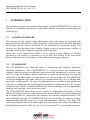
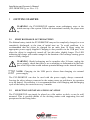
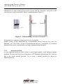
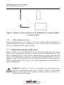
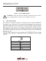
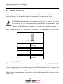
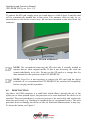
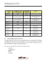
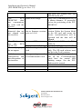
PVI-DESKTOP
Remote controller
INSTALLATION AND OPERATOR'S
MANUAL
Note: This document contains information that is the property of Power-One,
Inc. Reproduction, even partial, or transfer to third parties of the contents of this
document without the written consent of Power-One is strictly forbidden.
Model number: PVI-DESKTOP-yy-xx
Rev. 1.2
Installation and Operator's Manual
(PVI-DESKTOP-yy-xx Rev: 1.2)
TABLE OF REVISIONS
Document
Revision
Date
Description of changes
1.0
21/07/2009
First issue
1.1
29/12/2009
First revision
1.2
09/12/2009
Second Revision
KEEP THESE INSTRUCTIONS!
Installation and Operator's Manual
(PVI-DESKTOP-yy-xx Rev: 1.2)
INSTRUCTIONS FOR READING THE MANUAL
This manual contains important instructions for safety and operation which must be
understood and carefully followed during installation and maintenance of the
equipment.
In order to reduce the risk of damage and to be sure that the equipment is correctly
installed and ready to operate, special safety symbols are used in the manual to
highlight potential security risks or useful information. The symbols are as follows:
WARNING: Paragraphs marked with this symbol contain actions and
instructions which must be fully understood and followed in order to avoid
potential damage to the device or to persons.
NOTE: Paragraphs marked with this symbol contain actions and instructions
which must be fully understood and followed in order to avoid malfunction.
FCC NOTICE
The device complies with part 15 of the FCC rules. Operation is subjected to the
following 2 conditions: (1) this device may not cause harmful interference and (2) this
device must accept any interference received, including interference that may cause
undesired operation
FCC ID: X6W-DESKNOP
Installation and Operator's Manual
(PVI-DESKTOP-yy-xx Rev: 1.2)
CONTENTS
1
INTRODUCTION ......................................................................... 6
1.1
1.2
1.3
2
DESCRIPTION OF THE PVI-DESKTOP ................................. 9
2.1
2.2
2.3
3
AURORA INVERTERS............................................................................. 6
PVI-DESKTOP........................................................................................... 6
AVAILABLE MODELS ............................................................................ 7
DESCRIPTION OF THE DEVICE............................................................. 9
TECHNICAL CHARACTERISTICS....................................................... 12
PACKAGING CONTENTS ..................................................................... 13
GETTING STARTED................................................................. 15
3.1
FIRST RECHARGE OF THE BATTERY................................................ 15
3.2
SELECTION OF INSTALLATION LOCATION .................................... 15
3.2.1 Wall mounting ....................................................................................... 16
3.2.2 Installation on desk................................................................................ 17
3.2.3 Tips on the selection of installation location ......................................... 17
3.2.4 Antennas position .................................................................................. 18
3.2.5 Radio communication test ..................................................................... 19
3.3
OTHER PRELIMINARY OPERATIONS................................................ 19
4
SYSTEM INSTALLATION ....................................................... 21
5
DESCRIPTION OF THE MENU .............................................. 23
5.1
5.2
6
PVI-DESKTOP CONNECTIONS AND INTERFACES......... 25
6.1
6.2
6.3
6.4
6.5
6.6
6.7
6.8
7
DEFAULT SCREEN ................................................................................ 23
MENU....................................................................................................... 24
POWER SUPPLY CONNECTOR............................................................ 25
USB CONNECTOR ................................................................................. 26
RS485 CONNECTOR .............................................................................. 27
SD CARD SLOT....................................................................................... 27
RESET BUTTON ..................................................................................... 28
STATUS LED........................................................................................... 29
BLUETOOTH® (OPTIONAL) ................................................................. 29
TOUCH SCREEN..................................................................................... 30
SYSTEM OPERATION ............................................................. 31
Installation and Operator's Manual
(PVI-DESKTOP-yy-xx Rev: 1.2)
8
FIRMWARE UPGRADING.......................................................32
8.1
FW UPGRADING PROCEDURE USING AURORA COMMUNICATORE AND USB
CONNECTION ............................................................................................................32
8.2
HOW TO SAVE THE NEW FW IN YOUR PC ...................................................35
8.3
UPGRADING VIA SD CARD .........................................................................37
8.4
USB 2.0 DRIVER INSTALLATION ................................................................38
9
COMPATIBILITY AND BEST USE ........................................42
9.1
9.2
9.3
10
OPERATING SYSTEM COMPATIBILITY .........................................................42
COMPATIBILITY WITH INVERTERS ..............................................................42
DATA MANAGEMENT IN THE SD CARD .......................................................43
TROUBLESHOOTING GUIDE............................................44
Installation and Operator's Manual
(PVI-DESKTOP-yy-xx Rev: 1.2)
1
INTRODUCTION
This document contains the technical description of the PVI-DESKTOP. The user will
find all the information needed for configuration and for the proper operation and use
of the device.
1.1
AURORA INVERTERS
The inverters for the Aurora range photovoltaic and wind plants are equipped with
internal software that allows several parameters to be monitored for both the operation
of the plant and the inverter itself and for the production of measured energy. The
inverters are also provided with a display (liquid crystal or monochrome) capable of
showing sensitive data simply by using the built-in keypad.
Often, due to the limited accessibility of the system, remote display of all data
recorded by the inverter is necessary so as to have full control of the conversion
device's functions and, at the same, to check the actual energy production.
1.2
PVI-DESKTOP
The PVI-DESKTOP can fulfil the tasks of monitoring and remotely displaying
important parameters. The PVI-DESKTOP is a device which can communicate
remotely with the inverters in different ways, present the information of interest to the
user on a large TFT display, process and store a wealth of information covering the
whole life of the photovoltaic or wind system. As well as all this, the PVI-DESKTOP
can also communicate with other devices (e.g. normal home PCs) via a USB port and,
optionally, via Bluetooth®; this type of communication is possible by using dedicated
software for monitoring the Aurora inverters through a connection with a PC, Aurora
Communicator, which is always included in the inverter package CD and upgradeable
from the web site http:\\www.power-one.com\.
The PVI-DESKTOP thus allows you to replace or supplement the display of data
carried out remotely via the cable between the inverter RS485 port and an input port
on a normal home PC (and which still requires the software mentioned above). The
main advantage of using a PVI-DESKTOP lies in the possibility of setting up wireless
communication and the absence of wired communication. Moreover the large TFT
touch screen display allows the data acquired by the system to be easily and intuitively
displayed and processed. This way the use of an external PC is not strictly necessary.
Installation and Operator's Manual
(PVI-DESKTOP-yy-xx Rev: 1.2)
Connection to an external PC is only necessary for upgrading the internal firmware or
downloading the data collected by using Aurora Communicator.
Figure 1 shows a diagram summarizing the connections possible with the PVIDESKTOP, both to the inverters and a traditional PC.
P1 Server
868/915MHz
868/915MHz
RS485
868/915MHz
RS485
868/915MHz
optional
RS485
USB2
AURORA
Desktop
Personal
Computer
Internet
Figure 1 – Simplified connection diagram for the PVI-DESKTOP
1.3
AVAILABLE MODELS
Several versions can be purchased and they differ by their features or added
components. The various models are identified by the P/N:
PVI-DESKTOP-yy-xx
Where, field yy shows the characters BT if the model is equipped with a Bluetooth®
peripheral (otherwise this field is not in the P/N), and field xx shows two characters
identifying the national code which distinguishes the different mains sockets for the
charger. Some examples:
Installation and Operator's Manual
(PVI-DESKTOP-yy-xx Rev: 1.2)
PVI-DESKTOP-IT model without Bluetooth® peripheral and power supply/battery
charger with Italian mains socket
PVI-DESKTOP-BT-UK model with Bluetooth® peripheral and power
supply/battery charger with English mains socket
Installation and Operator's Manual
(PVI-DESKTOP-yy-xx Rev: 1.2)
2
2.1
DESCRIPTION OF THE PVI-DESKTOP
DESCRIPTION OF THE DEVICE
For proper use of the PVI-DESKTOP, you are recommended to look carefully at
Figure 2 to learn how to identify all the parts of the object.
1
6
9
8
7
5
4
Installation and Operator's Manual
(PVI-DESKTOP-yy-xx Rev: 1.2)
12
11
10
13
3
2
Figure 2 - Position of the components
1.
2.
3.
4.
5.
6.
7.
8.
9.
10.
11.
12.
13.
PVI-DESKTOP
Docking station
Holes for wall mounting
Touch Screen display
Multicolour LED status indicator
ON/OFF Button
RS485 communication port
USB 2.0 communication port
Reset button (internal)
Power supply input
Sound output holes
Stylus Pen positioning groove
SD card connector
Installation and Operator's Manual
(PVI-DESKTOP-yy-xx Rev: 1.2)
WARNING: Component 7. is a connector to be used solely and exclusively
for connection by RS485 to the Aurora inverters, when used. On no account
use it for anything else (e.g. connection of Ethernet cables for PC or
telephone connections) to prevent damage to the communication port.
The following figure also illustrates the location of the internal components of the
PVI-DESKTOP and the mechanical parts that make it up. The drawing is shown
purely for information purposes, since any disassembly or operation on the electronics
of the PVI-DESKTOP, including replacement of the Lithium battery, must be carried
out by specialist staff.
Figure 3 - Mechanical blow-up diagram
WARNING: the PVI-DESKTOP is fitted with security labels which, if
removed or showing scratch marks, render the warranty null and void.
Maintenance operations and replacement of components on the PVIDESKTOP can only be carried out by qualified specialist staff.
Installation and Operator's Manual
(PVI-DESKTOP-yy-xx Rev: 1.2)
2.2
TECHNICAL CHARACTERISTICS
The technical characteristics of the PVI-DESKTOP display and remote control device
are summarized in the following table.
Inverter radio communication frequency for
European models
Inverter radio communication frequency for USA
models
Inverter radio communication frequency for
Australian models
Communication range with radiomodule1
Bluetooth
Bluetooth communication frequency
Bluetooth range1
USB 2.0 port
RS485 communication port
Maximum RS485 cable length
Included SD Card capacity
Graphical display resolution
Graphical display dimensions
Touch Panel
Battery capacity
Standby2
Full charge time via power supply
Full charge time via USB 2.0
Voltage and current from power supply
Maximum current from USB 2.0
Software upgrade
Restoration of default settings
Status indicator
868.25 MHz, single channel
with 500 kHz bandwidth
63 channles from 902.65MHz
to 927.45MHz
30 channles from 915.8MHz
to 927.45MHz
300 m
Optional
2.4 GHz
20 m
present
present
200 m
1 Gb
320 x 240 QVGA
3.5”
4-wire resistive
1950 mAh
3 weeks
6h
8h
5V 1A DC
500 mA
Free via web3
Reset button
Three-colour LED
1
The specified range is significant only in the open and in the absence of
obstacles to the radio signal
2
The standby time indicated was measured in standard operating conditions
(radio communication every 15 minutes, power sleep enabled at 1 minute)
3
See website www.power-one.com
Installation and Operator's Manual
(PVI-DESKTOP-yy-xx Rev: 1.2)
2.3
PACKAGING CONTENTS
Inside the packaging and in addition to the PVI-DESKTOP and its docking station, are
some accessories, some of which have already been positioned in the PVI-DESKTOP.
These accessories are indicated and recognisable from the following figure.
16
18
14
15
17
x2
14.
15.
16.
17.
18.
USB cable
SD Card
Stylus Pen
DC 5V 1A power supply
Wall mounting kit (2 dowels + 2 universal screws)
NOTE: The distributor has delivered your PVI-DESKTOP to the carrier
packed securely and in perfect condition. The carrier, by accepting the
package, takes responsibility for it up to delivery. Despite the care exercised
by the carrier, it is possible that the package and its contents may be damaged
during transport.
The customer is recommended to carry out the following checks:
Examine the shipping container for signs of visible damage: holes, cracks or any
other sign of internal damage;
Describe any damage or missing parts on records of receipt, and obtain the
signature of the carrier and its full name;
Open the shipping container and examine the contents for signs of any damage
inside. When unpacking be careful not to discard equipment, components or
manuals. If damage is found, contact the shipper to determine the type of
intervention appropriate. An inspection may be required; store all the packing
material for the inspector!
Installation and Operator's Manual
(PVI-DESKTOP-yy-xx Rev: 1.2)
If the inspection reveals damage, call your local supplier, or authorized
distributor. They will decide whether the equipment should be returned for repair
and provide instructions in this regard;
It is the customer's responsibility to make a complaint with the carrier. Omission
of this procedure may result in the loss of warranty service for any damage
reported;
Keep the PVI-DESKTOP's original packaging in a safe place; should it be sent
for repair, it is necessary to use the original packaging.
Installation and Operator's Manual
(PVI-DESKTOP-yy-xx Rev: 1.2)
3
GETTING STARTED
WARNING: the PVI-DESKTOP requires some preliminary steps at the
initial start up of the system. Follow the instructions carefully for proper start
up.
3.1
FIRST RECHARGE OF THE BATTERY
The lithium battery inside the PVI-DESKTOP may not be completely charged, or even
completely discharged, at the time of initial start up. To avoid problems, it is
recommended that the object be charged for no more than 10 hours using the
appropriate power supply supplied. Charging is also possible via the USB port, even
when the object is completely turned off, but this takes slightly longer. The LED
indicating the charge will remain orange for the duration of the recharge turning green
once it is fully charged.
WARNING: Should recharging not be complete after 10 hours, unplug the
power supply, check that there is no overheating or deformation in the back
part of the object that would indicate potential damage to the internal battery.
NOTE: Charging via the USB port is slower than charging via external
power supply.
The PVI-DESKTOP can also be used with the power supply always connected.
Leaving the object always connected to the mains causes no problem to its operation
or to the battery. Nevertheless, it is recommended that a full charging and discharging
cycle of the battery be carried out every 2 months.
3.2
SELECTION OF INSTALLATION LOCATION
The PVI-DESKTOP can simply be placed on a flat surface or desk, or can be wall
mounted. This is possible thanks to the docking station with supporting feet and
preruptures for the fixing holes.
Installation and Operator's Manual
(PVI-DESKTOP-yy-xx Rev: 1.2)
3.2.1
Wall mounting
Choosing the location carefully for wall mounting is essential for comfortable and
easy reading of data. It is recommended the PVI-DESKTOP is not installed above or
near heat sources (e.g. radiators, stoves or other sources of heat) to avoid damage to
the object. Avoid installing the object in the vicinity of large metallic parts (e.g.
boilers, steel doors, various kinds of metal boxes, etc.) in order not to limit the
operating efficiency of radio communication or Bluetooth®. It is furthermore
recommended that areas where the incidence of direct light may make it impossible to
read the display correctly and even lead to discolouration of the external plastic are
avoided. The following figures illustrate the procedure for proper wall mounting.
Figure 4 - Wall mounting procedure
Drill two holes, diameter 5 mm and minimum depth 45 mm, 3 cm apart from each
other (Figure 4.a.). Insert the dowels (Figure 4.b.). Screw the base to the wall using the
screws provided (Figure 4.c.)
Installation and Operator's Manual
(PVI-DESKTOP-yy-xx Rev: 1.2)
The PVI-DESKTOP support base is designed to make it easy to remove the object
even with the power or communication cables inserted. Moreover, if properly
installed, the PVI-DESKTOP will be perfectly parallel to the wall chosen.
NOTE: The physical characteristics of the installation location (wall
thickness, presence of metal or glass walls, distance from the Aurora inverter,
etc.) may limit the range of the radio signal. It is recommended that, once a
plausible location for mounting has been identified, a radio communication
test is carried out before the actual installation.
3.2.2
Installation on desk
The PVI-DESKTOP base enables comfortable and solid positioning on flat surfaces
such as tables or desks. The inclination of about 10° of the axis allows for easier
reading of the display and more convenient use of the touch screen. It is recommended
the PVI-DESKTOP is not installed above or near heat sources (e.g. radiators, stoves or
other sources of heat) to avoid damage to the object. Avoid installing the object in the
vicinity of large metallic parts (e.g. boilers, steel doors, various kinds of metal boxes,
etc.) in order not to limit the operating efficiency of radio communication or
Bluetooth®. It is furthermore recommended that areas where the incidence of direct
light may make it impossible to read the display correctly and even lead to
discolouration of the external plastic are avoided.
NOTE: The physical characteristics of the installation location (wall
thickness, presence of metal or glass walls, distance from the Aurora inverter,
etc.) may limit the range of the radio signal. It is recommended that, once a
plausible location for mounting has been identified, a radio communication
test is carried out before the actual installation.
3.2.3
Tips on the selection of installation location
The selection of installation location and the position of the PVI-DESKTOP strongly
influence the quality of the radio signal received. Choosing to leave the PVIDESKTOP resting on a desk free of obstacles and objects in a 20 cm radius allows the
best radio signal reception. If you choose wall mounting, take into account some rules
that allow data reception to be much improved. Avoid, for example, installing the PVI-
Installation and Operator's Manual
(PVI-DESKTOP-yy-xx Rev: 1.2)
DESKTOP on walls coming between the inverter and the controller, and prefer walls
which do not come between the line of communication (Figure 5).
Figure 5 - Wall mounting, selection of location
Keep metal or conductive objects as far away as possible.
Signal quality is also influenced by environmental factors such as fog, rain, air
humidity, etc. The effect of these environmental factors is negligible over limited
distances but can be considerable over long communication distances.
3.2.4
Antennas position
A very important factor in order to have a good signal quality is the antennas mutual
position. Do not point the inverter antenna to PVI-Desktop (figureFigura 6.b) becasue
this is the worst mutual position. Try to keep a mutual position as shown in
figureFigura 6.a.
Installation and Operator's Manual
(PVI-DESKTOP-yy-xx Rev: 1.2)
Figura 6 - Posizione reciproca di antenna e PVI-DESKTOP (a. ricezione ottimale,
b. ricezione debole)
3.2.5
Radio communication test
To test communication, it is possible to carry out a simple plant configuration as
shown in paragraph 4 point 2). Appearance of your inverter in the list of associable
devices is confirmation radio signal reception.
3.3
OTHER PRELIMINARY OPERATIONS
Before starting up the PVI-DESKTOP for the first time, make sure the Aurora
inverters have been properly configured. Check that the PVI-RADIOMODULE card
has been installed in the Aurora inverters, should activation of radio communication
with the PVI-DESKTOP be desired. To install the PVI-RADIOMODULE reference
should be made to the applicable manual. Check that the cable is long enough for
RS485 communication, if you desire to use wired configuration as an alternative to
radio communication.
WARNING: Connector 7. Figure 2 is reserved for use with special wiring
for RS485 communication with Aurora inverters. Under no circumstances
connect with any other device (Ethernet, telephone network or other) as it
could lead to possible damage.
Installation and Operator's Manual
(PVI-DESKTOP-yy-xx Rev: 1.2)
Check that the SD card is inserted correctly before turning on the device. The SD card
is an integral part of the device and is absolutely necessary for its operation. Missing
or incorrect insertion of the SD card generates an easily recognizable error message on
the display.
Installation and Operator's Manual
(PVI-DESKTOP-yy-xx Rev: 1.2)
4
SYSTEM INSTALLATION
When all the preliminary steps (see § 3) have been carried out, the initial start up of
the communication system can proceed. For proper initial start up follow the
operations indicated in the following paragraphs scrupulously.
1) Inverter configuration and device switch on
•
•
•
•
Check that the PVI-RADIOMODULE is correctly installed (see the PVIRADIOMODULE manual) if you want to initialize radio communication.
Check that the Aurora inverters in your photovoltaic/wind plant are turned on.
Check that the addresses for the RS485 ports are all different (they do not
need to be sequential).
Check that the RS485 wiring is correct and inserted if you want to initialize
RS485 cable communication.
2) Switching on the PVI-DESKTOP and inverter association
•
•
•
•
•
•
Switch on the device by pressing the ON/OFF button and follow the
instructions that appear on the display, select the desired values and click on
next.
Set the date and current time.
Please note that you can change the setting at any time through the "Settings Date - Time" menu.
Select the communication channel: select the box corresponding to the
communication channel that will be used (Radio or RS485).
Select the number of inverters that will be connected to the PVI-DESKTOP
(from 1 to 6).
Select how often you want a data read refresh. The time is selectable from a
minimum of 1 minute to a maximum of 15 minutes.
Scan the communication channel to search for inverters or choose to defer the
operation to a later time.
Installation and Operator's Manual
(PVI-DESKTOP-yy-xx Rev: 1.2)
•
•
•
•
•
•
•
If you decide to carry out the scan, the PVI-DESKTOP will begin to
interrogate the various addresses until has found a number of inverters
corresponding to the one set in the configuration process. During scanning, a
screen showing a table with an indication of the state of scanning will appear.
At the end of scanning, the table will show the models and serial numbers of
the inverters found.
At this point it is possible to choose which inverter(s) to associate uniquely
with your PVI-DESKTOP so that they cannot be seen and recognised by
other PVI-DESKTOPs nearby. The selection is made by pressing the '+' key
next to each inverter chosen. Pressing the '+' key changes the colour of the
corresponding row in the table by highlighting the selection.
It is advisable to check that the serial numbers of the inverters chosen
correspond to those of the inverters in your system to avoid associating
inverters from other systems nearby with your PVI-DESKTOP.
At this point the system is configured and, automatically, starts the
synchronization procedure for the timetable of the monitored inverters and
data acquisition from the inverters. The first synchronization can also take a
very long time because of the high amount of historical data that the inverters
will send to the PVI-DESKTOP.
On the other hand, if the channel scan is unsuccessful, an error message and a
request to repeat the scan will be displayed.
To determine the causes of non-recognition of the inverters, consult the
troubleshooting guide attached to the manual
3) Inverter disassociation or need for reconfiguration
Whenever it may be necessary to delete one or more associated inverters from your
list, it is necessary to run the guided procedure again, accessing it from the “Settings –
Configuration wizard" menu. On appearance of the table with the associated serial
numbers, simply click on the '-' key to deselect the inverter and delete it from the
associated list.
Any time a re-configuration is necessary, you must carry out the guided procedure.
NOTE: The guided configuration procedure is necessary, for example, when
an inverter is replaced or an inverter is added for monitoring.
Installation and Operator's Manual
(PVI-DESKTOP-yy-xx Rev: 1.2)
5
5.1
DESCRIPTION OF THE MENU
DEFAULT SCREEN
The PVI-DESKTOP remains, by default, on an intuitive screen that summarizes the
system's important data and operating status. The screen is shown in the figure below.
Each inverter in the system is surrounded by a line indicating different states
depending on the colour:
Green line - Inverter connected and running correctly
Yellow line - Inverter on but not yet connected to the network
Red line - Inverter in alarm
Blue line - Inverter off or no radio or wired communication
If you click (single click) on each inverter you will see a bubble showing the
recognition data for the individual inverter and its operating status.
The top bar contains the information regarding date and time, battery status, the power
of the radio signal received and the radio communication icon. The central black band
shows the summary data for the whole system. Clicking on any point in the black band
gives you a detailed view of the system. The screen that opens is detailed in the
following figure.
Installation and Operator's Manual
(PVI-DESKTOP-yy-xx Rev: 1.2)
The screen shows the graph of the power produced by the system and, by clicking on
the relative tab, by each individual inverter. The right side also summarises the
sensitive parameters. The central black band and top bar show exactly the same data as
the default screen.
By clicking on the tabs, you select the graphs and data for each individual inverter
(INV.N) or the complete system (SYS); the tab also has indications that are always
visible reporting the status of each individual inverter and a power meter that indicates
the power exported in the form of a graph.
5.2
MENU
You enter the main screen from the previous screens, by clicking on the menu key.
The PVI-DESKTOP menu is divided into sections and each section has several submenus to view, set or change the settings of the object.
• Statistics Menu
In this section you can recall all the production data for the system for certain time
intervals. Sub-sections indicate the time interval for which you want to see the
production data (total, Partial, Today, 7 days, 30 days, 365 days, User).
• Settings Menu
In this section you can enter or change the object's configuration parameters. The first
heading "Date-Time" allows you to change the date and time set. The second heading
"Money" allows you to enter the current exchange rate for calculating savings. The
heading "display" sets the brightness and recalibrates the touch screen.
Installation and Operator's Manual
(PVI-DESKTOP-yy-xx Rev: 1.2)
Successively there are the "Language" sub-section, which allows you to set the system
language, the "Configuration Wizard", which allows the communication channel to be
re-configured, and the "Firmware Update" from which you can upgrade the PVIDESKTOP firmware to the latest level. The "Sleep" heading, on the other hand, allows
the battery save function to be activated. This function can be enabled or disabled at
set time intervals. For the new software installation procedure, please refer to the
applicable section.
Models with Bluetooth® will also have a heading in this menu dedicated to the
enabling/disabling of the peripheral.
• Info Menu
In the sub-sections of this menu you can get information about the PVI-DESKTOP
serial number and the firmware version installed.
6
PVI-DESKTOP CONNECTIONS AND INTERFACES
The PVI-DESKTOP is equipped with different types of connection and interface that
connect it directly to the Aurora inverters or a traditional PC. The following
paragraphs describe the capabilities and limitations of using the connections on the
object.
WARNING: The instructions shown in the following paragraphs are
essential for avoiding potential damage to the device. Any use of connections
other than those indicated is potentially harmful to the PVI-DESKTOP.
6.1
POWER SUPPLY CONNECTOR
At the back of the device there is the input connector for the power supply. The
electrical input characteristics are shown marked near the connector itself. Figure 2
shows the location of the connector and details stamped. Use the power supply
provided to supply the device.
Installation and Operator's Manual
(PVI-DESKTOP-yy-xx Rev: 1.2)
Figure 7 - power supply polarity
WARNING: Follow the directions regarding voltage and current as well as
those regarding polarity in order to prevent damage to the device.
6.2
USB CONNECTOR
The connector to the USB 2.0 interface is located on one side of the PVI-DESKTOP.
The connector is a USB mini B and is used with the cable supplied. The interface is
designed to connect the device to a normal PC with a USB port. Insertion of other
types of peripheral such as mass storage keys, external hard disks, mobile telephones,
MP3 players and other devices is not permitted. Communication with the PC occurs
after installation of the special drivers and through the software on the CD attached to
the packaging. Through the software you can download the data in the PVI-DESKTOP
and store it on a PC.
The USB connector can also be used to recharge the PVI-DESKTOP. Please note that
charging via the USB port is considerably slower than through the power supply
connector.
pin no.
1
2
3
4
5
shield
function
+5V
DD+
ID
GND
GND
Installation and Operator's Manual
(PVI-DESKTOP-yy-xx Rev: 1.2)
6.3
RS485 CONNECTOR
The entry to the RS485 port is located just below the USB connector. This port is to be
used exclusively for connection to the Aurora inverters by appropriate wiring.
WARNING: As indicated on the protection label, the J1 connector in Figure
2 is reserved for use with special wiring for RS485 communication with
Aurora inverters. Under no circumstances connect with any other device
(Ethernet, telephone network or other) as it could lead to possible damage.
This connection can be used as an alternative or supplement to the radio
communication with the inverters.
pin no.
1
2
3
4
5
6
7
8
6.4
function
not used
not used
D+
not used
Dnot used
GND
not used
SD CARD SLOT
The slot dedicated to the SD card is located at the bottom of the PVI-DESKTOP.
When the card is not inserted or contains no recognisable data, this device shows an
error message on the display which disappears only after the insertion of a correct SD
card. The SD card has some graphics features and other elements essential to the
object's operation stored in it. This card is also capable of storing, if necessary, the
field inverter data and making it available to other dedicated software on other devices
such as PCs.
Installation and Operator's Manual
(PVI-DESKTOP-yy-xx Rev: 1.2)
To remove the SD card, simply press on it until there is a click (Figure 8) and the card
will be automatically pushed out at that point. The memory card can only be reinserted into its slot in one correct way; do not force insertion as this may break the
connector.
press here
Figure 8 - SD card withdrawal
NOTE: We recommend removing the SD card only if actually needed to
transfer data to other support media. If this is not necessary, the card can
remain indefinitely in its slot. Do not use the SD card as a storage disc for
data unrelated to the operation of the PVI-DESKTOP.
NOTE: Even if it is not necessary to remove the SD card with the object
switched off, we recommend the PVI-DESKTOP be switched off completely
before carrying out this operation.
6.5
RESET BUTTON
Just above the USB connector is a small hole which allows, through the use of the
stylus pen or other pointed object, the processor to be reset and hence the device to be
restarted. The reset procedure is a recovery process to be used solely and exclusively
when the need arises (e.g. blocking of operation due to exceptional events). The reset
procedure does not damage the device or alter its functional characteristics in any way.
To locate the button, see Figure 2.
Installation and Operator's Manual
(PVI-DESKTOP-yy-xx Rev: 1.2)
6.6
STATUS LED
At the top right of the display there is a LED status indicator. This LED will take on
different colours depending on the operating status of the PVI-DESKTOP. Figure 2
identifies the position of the LED. The following table is an aid to distinguishing the
different states of operation, the corresponding colours and the corresponding
operating states of the PVI-DESKTOP.
LED COLOUR
LED off
Steady green LED
on
Steady orange
LED on
Red LED flashing
Blue LED
flashing
6.7
INDICATION
- No power connected (DC or USB)
- Battery charged, at least one power supply connected (DC or
USB), device on standby
- Battery charging
- Battery flat
- Aurora Desk on standby
BLUETOOTH® (OPTIONAL)
There is the possibility of having a Bluetooth® module as an optional interface for the
PVI-DESKTOP. This interface allows communication with PCs equipped with
Bluetooth® and dedicated software. It carries out all the functions implemented on the
USB port for data exchange and firmware upgrades.
Under normal operating conditions, the Bluetooth® function is disabled to eliminate
unnecessary power consumption. To enable this function you need to access the
appropriate menu.
NOTE: We recommend using Bluetooth® only when necessary and
disabling it immediately after use so as not to drain the battery quickly.
Installation and Operator's Manual
(PVI-DESKTOP-yy-xx Rev: 1.2)
6.8
TOUCH SCREEN
The PVI-DESKTOP is equipped with a resistive touch screen that allows easy and fast
navigation through the menus without pressing a keyboard, etc. At the back (see
Figure 2) there is a space where a stylus pen, for use to apply pressure on the screen,
can be inserted. The screen is sensitive to pressure from any object (fingers, pens, etc)
and only a light touch is needed to activate it. If necessary, there is a touch screen
calibration procedure that allows any errors in reading the pressure to be corrected.
WARNING: Take care to avoid touching the touch screen with sharp or
pointed objects or applying excessive pressure on the surface. Do not scratch,
strike violently or scrape the display surface and only use products specially
designed for cleaning LCD screens. Damage to the touch screen seriously
undermines the object's operating efficiency.
NOTE: We recommend using the stylus pen to prevent any staining or
soiling to the display surface.
Installation and Operator's Manual
(PVI-DESKTOP-yy-xx Rev: 1.2)
7
SYSTEM OPERATION
Once the PVI-DESKTOP has been configured, it operates automatically and continues
to make data requests to the associated inverters, storing the replies. The device will
pass through different states during the process of normal operation. In particular, the
PVI-DESKTOP can be in three different conditions:
•
•
•
•
FULL-ON MODE; in this mode the display is on and all functions are 100%
active. Every touch in an active area of the touch screen will make the page
change and execute the set commands.
STAND-BY MODE; in this mode the PVI-DESKTOP display will be off, but
the object will be ready to react to a touch on the touch screen. The radio and
RS485 peripherals are 100% operational. A flashing blue LED will indicate
this state. The PVI-DESKTOP automatically goes into standby 1 minute after
the last touch screen command.
SLEEP MODE; in this mode the whole system is on minimum consumption.
The peripherals are off and come back on automatically to send data requests
to the inverters. The user will not see any indication from the PVIDESKTOP. The device will go into this state only if it has been enabled
through the appropriate menu and after a time that can be set. To re-awaken
the system, press the ON/OFF key for at least one second.
OFF MODE; by pressing the ON/OFF key for at least 5 seconds, a screen
will appear asking if you want to turn it off. By pressing 'OK', the object will
switch off completely and will not send any data requests by radio or RS485,
or perform any other operation, until it is switched back on. To switch the
PVI-DESKTOP back on, simply press the ON/OFF key.
Installation and Operator's Manual
(PVI-DESKTOP-yy-xx Rev: 1.2)
8
FIRMWARE UPGRADING
8.1
FW Upgrading procedure using Aurora Communicatore and USB
connection
1.
Download the latest version of the Aurora Communicator Software. The
latest release of the SW is available at the following link: http://www.powerone.it/digilab/Digi.aspx?Code=15
2.
Click on Donwload to save the correct version of the SW with respect to the
OS version (32 or 64bit).
Unzip the file and launch the setup.exe to start installation.
In case a previous version of the Aurora Communicator is present on the PC,
it’s strongly recommended to uninstall it before to launch the installation of
the downloaded version.
During the FW upgrading make sure all the other programs are shut-off.
To complete this operation it’s mandatory to have an active USB connection
with the PVI-DESKTOP and an active connection to internet to make
possible the connection to the Power-One’s server for the FW downloading
Launch the Aurora Communicator SW From the Configuration menu, choose
Aurora PVI-DESKTOP Update.
3.
4.
5.
6.
7.
Installation and Operator's Manual
(PVI-DESKTOP-yy-xx Rev: 1.2)
8.
Click on Test Device to verify the connection with the PVI-DESKTOP is
correctly working. In case the connection is up and running, will be possible
to read the device S/N, device P/N, production WK, actual FW version, actual
Boot version. In the bottom-left corner the message “Device found” will
appears. In addition the other buttons will be enabled.
9.
Click on Web Update to connect to the PowerOne server. From the list of the
available FW, select the desired one (the latest available will always be on the
top of the list) and click on Update to start the FW upgrading process
Installation and Operator's Manual
(PVI-DESKTOP-yy-xx Rev: 1.2)
10. The FW upgrading process will be completed after three operations will be
successfully completed. During the FW upgrading process the PVIDESKTOP will show the message “FW Upgrading” at display:
“memory section erasing”
“FW writing”
“FW verification”
11. Once the three steps are successfully completed, it’s possible to change the
FW revision. Click on Change Revision to view the available FW version
into the PVI-DESKTOP, choose the desired version (the latest downloaded)
and click on OK:
Installation and Operator's Manual
(PVI-DESKTOP-yy-xx Rev: 1.2)
12. Below some screenshot of the Aurora Communicator SW during the revision
change. During this period the display of the PVI-DESKTOP doesn’t show
any information about the process. The user can check the state of the
procedure by Aurora Communicator SW display messages, at the last step the
PVI-DESKTOP will restart by itself. After the restart is complete, Aurora
Communicator SW will check that the new PVI-DESKTOP revision is ready.
It is recommended to not disconnect the USB since the PVI-DESKTOP has
completed the restart.
8.2
How to save the new FW in your PC
1.
2.
It’s possible to save the new FW file on the HDD to perform the FW
upgrading in a second step. In this case, the operation can be done even in
case the USB connection with the PVI-DESKTOP is not available (i.e. the
test device is impossible). In any case to complete this operation is mandatory
the PC has an active connection to internet to make possible the connection to
the Power-One’s server for the FW downloading.
If the USB connection is available, launch the Aurora Communicator SW.
From the Configuration menu choose Aurora PVI- Desktop Update.
Installation and Operator's Manual
(PVI-DESKTOP-yy-xx Rev: 1.2)
3.
Click on Web Update to connect to the PowerOne server. From the list of the
available FW, select the desired one (the latest available will always be on the
top of the list) and click on Download to save the new FW upgrading file.
Save the file with the name in the following format: FWxxxx.ben, where
xxxx is the application’s name.
4.
If the USB connection is not available, launch the Aurora Communicator SW.
From the Configuration menu, choose Aurora PVI-Desktop Update
Click on Web Update, the SW will require an authentication key. You can
find the authorization at the following screen on the PVI-DESKTOP display:
Menu/Info/ID Aurora PVI Desktop.
Insert the authorization key (i.e. 10013I88) and select the desired new FW file
from the list of the available FW (the latest available will always be on the
top of the list). Click on Download to save the new FW upgrading file. Save
the file with the name in the following format: FWxxxx.ben, where xxxx is
the application’s name.
5.
6.
Installation and Operator's Manual
(PVI-DESKTOP-yy-xx Rev: 1.2)
7.
8.3
To update PVI-DESKTOP utilize Aurora Communicator SW choosing Open
file from following screenshot, then select Update.
Upgrading via SD card
1.
2.
3.
4.
5.
6.
7.
8.
Turn off the PVI-DESKTOP by pressing the ON/OFF key for more than 5
seconds and confirming on the display.
Take the SD card out of the PVI-DESKTOP by pressing it lightly (ref. §6.4.).
Insert the SD card into a reader connected to the PC.
Check the formatting of the SD card by right-clicking on the appropriate
drive and selecting properties. Check that the formatting is FAT and not
FAT32.
Open the SD card drive where you will find several folders (language, theme,
etc.) including the folder 'BOOT'. If the folder 'BOOT' does not exist, create
it.
Copy the file downloaded from the Power-One website into the 'BOOT'
folder and rename it as "boot.ben".
Remove the SD card reader from the PC following the safe hardware removal
procedure, take the SD card out of the reader and put it back in the PVIDESKTOP.
Switch the PVI-DESKTOP back on.
Installation and Operator's Manual
(PVI-DESKTOP-yy-xx Rev: 1.2)
9. Navigate the menu to select firmware upgrade (ref. §5.2.).
10. On clicking next, the PVI-DESKTOP will start the upgrade procedure.
11. Once the new software has been read and loaded, a selection dialogue will
appear on the screen. From this screen you can decide whether to install the
new firmware, return to the previous version or cancel the procedure and
keep the current firmware.
12. Wait until the PVI-DESKTOP finishes the installation operations to see the
menu automatically reappear.
It takes several minutes for the process to conclude and the display will show a screen
with the words "Boot...' during this time. This screen is completely normal and will
automatically disappear at the end of the process.
8.4
USB 2.0 Driver installation
1.
2.
Download the latest release of the PVI-Desktop USB Driver at the following
link: http://www.power-one.it/digilab/Digi.aspx?Code=15
Click on “Download” and save the AuroraPVIDesktop-inf.zip file in a
convenient folder on the PC (in the following will be considered C:/).
3. Unzip the file: the contents will be:
mchpcdc.inf
mchpcdc.cat
4. Using the USB cable included in the PVI-Desktop box, connect the device to
the PC.
Installation and Operator's Manual
(PVI-DESKTOP-yy-xx Rev: 1.2)
5.
6.
It’s strongly recommended to connect directly the device to the PC. The
usage of HUB or docking station could result in some installation problems.
Make sure the PVI-DESKTOP is turned on.
The system will recognize a new hardware and will start the installation
wizard. Select “No, not now” and click on Next>:
7.
Select “Install from a specific path (advanced user)” and click Next>:
8.
9.
Include the folder where the driver are located (C:/) and click Next>.
When the following screenshot will appear, click on Continue.
Installation and Operator's Manual
(PVI-DESKTOP-yy-xx Rev: 1.2)
10. Let the system completing the drivers installation
11. When the installation is completed click on Finish.
Installation and Operator's Manual
(PVI-DESKTOP-yy-xx Rev: 1.2)
12. In order to check the correct installation of the driver open the Control Panel
of the system, choose System and switch on the Hardware tab:
13. In the Ports (COM and LPT) section check the new COM port and note the
COM port number (in the example Com 14):
Installation and Operator's Manual
(PVI-DESKTOP-yy-xx Rev: 1.2)
9
COMPATIBILITY AND BEST USE
9.1
Operating system compatibility
The PVI-DESKTOP can be used on and is compatible with the following operating
systems:
-
Windows XP version 2002 (Home, Professional), Service Pack 3
Windows 2000
Windows 7
Further updates and compatibility with new operating systems can be seen on the
website.
9.2
Compatibility with inverters
The use of wireless or wired connection requires that PVI-RADIOMODULE cards be
inserted in the AURORA inverters or that they have an RS485 port. Current system
compatibility is summarised in the following table
Installation and Operator's Manual
(PVI-DESKTOP-yy-xx Rev: 1.2)
INVERTER
model
PVI-12.5
PVI-10.0
PVI-6.0
Compatible with
PVI-Radiomodule
YES
YES
Units produced after
week: wk32/09
Compatible
with RS485
YES
YES
YES
PVI-5.0
Units produced after
week: wk32/09
YES
PVI-4.2
PVI-3.6
PVI-3.0
PVI-3600
Indoor
YES
YES
YES
YES
YES
YES
YES
YES
PVI-2000
Indoor
YES
YES
PVI-3600
Outdoor
NO
YES
PVI-2000
Outdoor
NO
YES
9.3
Notes
A firmware upgrade is
necessary for previous
inverters
A firmware upgrade is
necessary for previous
inverters
Starting from version FW 11
of the PVIRADIOMODULE
Starting from version FW 11
of the PVIRADIOMODULE
Starting from version FW 11
of the PVIRADIOMODULE
Starting from version FW 11
of the PVIRADIOMODULE
Data management in the SD card
The data stored on the SD card are accessible and can be stored. The only folders
containing important data for energy production are the ones identified by “System”
and "SNxxyyzz” which gather the actual data. The other folders hold information for
the PVI-DESKTOP images, sounds and languages.
The structure of the folders on the SD card is shown below:
-
THEME **
LANGUAGE **
SOUND **
BOOT
SYSTEM
Installation and Operator's Manual
(PVI-DESKTOP-yy-xx Rev: 1.2)
-
SNxxyyzz (1 folder for each field inverter)
The folders identified by ** are folders containing the PVI-DESKTOP's own data and
must never be edited or deleted so as not to lose the device's operating efficiency. In
the event of accidental editing or deletion a recovery copy of the SD card must be
downloaded from the P1 portal.
The “System” and “SNxxyyzz” folders contain synchronised data and data stored
daily; the files are in .xml format. The files marked by the name “DAYxxxx.xml”
contain the daily graphs stored by the PVI-DESKTOP whilst the “DATA.xml” files
contain the historical data contained in the inverters and downloaded by the PVIDESKTOP during synchronisation. Deletion of “DATA.xml” simply means the PVIDESKTOP will have to be re-synchronised with the inverters and the historical data
restored. On the other hand deletion of “DAYxxxx.xml” causes the unrecoverable loss
of the data for the day. It is advisable to save periodically (annually) to avoid the loss
of data. For the meaning of the “BOOT” folder see paragraph 8.2.
WARNING: We strongly recommend you handle the files directly from the
SD card without accessing them through Aurora Communicator. Any
unintentional editing of the files on the SD card seriously jeopardises the
object's operation. Always use the Aurora Communicator interface to process
and save data.
Aurora Communicator can display the total daily and historical production data, and
for each individual inverter of the photovoltaic field, on the PC. To do this just follow
paragraph 8.1 to point 3 and then select the data registry key. The screen that appears
will allow you to download the data and display them graphically.
10 TROUBLESHOOTING GUIDE
Some of the most common problems encountered, their possible causes and solutions
are shown below:
Problem
The
PVIDESKTOP
does
not switch on
Possible cause
Battery completely flat
Software failure
Solution
Attach the power supply provided
and check the orange LED is lit.
Try to switch it on
Attach the power supply provided
Installation and Operator's Manual
(PVI-DESKTOP-yy-xx Rev: 1.2)
and press the system reset key
with the stylus pen.
Carry out a communication test at
a shorter distance. If successful,
review the positioning of the PVIDESKTOP
The
PVIDESKTOP
does
not communicate
by radio with the
inverter
The
downloaded
historical data are
not aligned with
the inverter's
Radio out of range
The PC does not
see
the
PVIDESKTOP
The daily graphs
do not appear
Incorrect USB port
Failed
configuration and
non-recognition of
the inverters
Wrong settings on the
PVI-Radiomodule cards
Error in synchronisation
due to firmware versions
prior to 0.5.68
Drivers not installed
Failed writing in the SD
card
Upgrade the firmware to a later
version. Delete the System folder
in the SD card and restart the
device. Synchronisation will be
repeated and the data will be
aligned.
Check that the USB on the PC is
USB 2.0.
Install the USB drivers on the PC.
Check that the SD card is not read
only. The SD card selector must
not be in the 'Lock' position.
At the configuration stage check
that all the PVI-Radiomodule
cards have the central LED
flashing orange. See the PVIRadiomodule manual
YOUR WKtZͲKEDISTRIBUTOR
SOLIGENT
800-967-6917
www.soligent.net