1
Adjustable
Frequency AC Drive
Reference Manual
www.abpowerflex.com
Important User Information
Solid state equipment has operational characteristics differing from those of
electromechanical equipment. “Safety Guidelines for the Application,
Installation and Maintenance of Solid State Controls” (Publication SGI-1.1
available from your local Allen-Bradley Sales Office or online at http://
www.ab.com/manuals/gi) describes some important differences between
solid state equipment and hard-wired electromechanical devices. Because of
this difference, and also because of the wide variety of uses for solid state
equipment, all persons responsible for applying this equipment must satisfy
themselves that each intended application of this equipment is acceptable.
In no event will the Allen-Bradley Company be responsible or liable for
indirect or consequential damages resulting from the use or application of
this equipment.
The examples and diagrams in this manual are included solely for
illustrative purposes. Because of the many variables and requirements
associated with any particular installation, the Allen-Bradley Company
cannot assume responsibility or liability for actual use based on the
examples and diagrams.
No patent liability is assumed by Allen-Bradley Company with respect to
use of information, circuits, equipment, or software described in this
manual.
Reproduction of the contents of this manual, in whole or in part, without
written permission of the Allen-Bradley Company is prohibited.
Throughout this manual we use notes to make you aware of safety
considerations.
!
ATTENTION: Identifies information about practices or
circumstances that can lead to personal injury or death, property
damage, or economic loss.
Attentions help you:
• identify a hazard
• avoid the hazard
• recognize the consequences
Important: Identifies information that is especially important for successful
application and understanding of the product.
Shock Hazard labels may be located on or inside the drive to
alert people that dangerous voltage may be present.
DriveExplorer, DriveTools32, and SCANport are trademarks of Rockwell Automation.
PLC is a registered trademark of Rockwell Automation.
ControlNet is a trademark of ControlNet International, Ltd.
DeviceNet is a trademark of the Open DeviceNet Vendor Association.
COLOR-KEYED is a registered trademark of Thomas & Betts Corporation.
Table of Contents
Chapter 1
Specifications & Dimensions
PowerFlex 70/700 Specifications. . . . . . . . . . . . . . . . . . . . . . . . . . . . . . . . . . . . . . . . . . . . . . . . . . . . 1-1
Input/Output Ratings . . . . . . . . . . . . . . . . . . . . . . . . . . . . . . . . . . . . . . . . . . . . . . . . . . . . . . . . . . . . . 1-2
Heat Dissipation. . . . . . . . . . . . . . . . . . . . . . . . . . . . . . . . . . . . . . . . . . . . . . . . . . . . . . . . . . . . . . . . . 1-2
Derating Guidelines . . . . . . . . . . . . . . . . . . . . . . . . . . . . . . . . . . . . . . . . . . . . . . . . . . . . . . . . . . . . . . 1-3
PowerFlex 70 Dimensions . . . . . . . . . . . . . . . . . . . . . . . . . . . . . . . . . . . . . . . . . . . . . . . . . . . . . . . . . 1-5
PowerFlex 70 Flange Mount Dimensions . . . . . . . . . . . . . . . . . . . . . . . . . . . . . . . . . . . . . . . . . . . . . 1-8
PowerFlex 700 Dimensions . . . . . . . . . . . . . . . . . . . . . . . . . . . . . . . . . . . . . . . . . . . . . . . . . . . . . . . 1-16
Chapter 2
Detailed Drive Operation
Accel Time. . . . . . . . . . . . . . . . . . . . . . . . . . . . . . . . . . . . . . . . . . . . . . . . . . . . . . . . . . . . . . . . . . . . . 2-1
AC Supply Source Considerations . . . . . . . . . . . . . . . . . . . . . . . . . . . . . . . . . . . . . . . . . . . . . . . . . . 2-1
Alarms . . . . . . . . . . . . . . . . . . . . . . . . . . . . . . . . . . . . . . . . . . . . . . . . . . . . . . . . . . . . . . . . . . . . . . . . 2-2
Analog Inputs. . . . . . . . . . . . . . . . . . . . . . . . . . . . . . . . . . . . . . . . . . . . . . . . . . . . . . . . . . . . . . . . . . . 2-6
Analog Outputs . . . . . . . . . . . . . . . . . . . . . . . . . . . . . . . . . . . . . . . . . . . . . . . . . . . . . . . . . . . . . . . . 2-18
Auto / Manual . . . . . . . . . . . . . . . . . . . . . . . . . . . . . . . . . . . . . . . . . . . . . . . . . . . . . . . . . . . . . . . . . 2-22
Auto Restart (Reset/Run). . . . . . . . . . . . . . . . . . . . . . . . . . . . . . . . . . . . . . . . . . . . . . . . . . . . . . . . . 2-24
Bus Regulation. . . . . . . . . . . . . . . . . . . . . . . . . . . . . . . . . . . . . . . . . . . . . . . . . . . . . . . . . . . . . . . . . 2-26
Cable, Control . . . . . . . . . . . . . . . . . . . . . . . . . . . . . . . . . . . . . . . . . . . . . . . . . . . . . . . . . . . . . . . . . 2-30
Cable Entry Plate Removal . . . . . . . . . . . . . . . . . . . . . . . . . . . . . . . . . . . . . . . . . . . . . . . . . . . . . . . 2-30
Cable, Motor Lengths . . . . . . . . . . . . . . . . . . . . . . . . . . . . . . . . . . . . . . . . . . . . . . . . . . . . . . . . . . . 2-31
Cable, Power . . . . . . . . . . . . . . . . . . . . . . . . . . . . . . . . . . . . . . . . . . . . . . . . . . . . . . . . . . . . . . . . . . 2-33
Cable, Standard I/O . . . . . . . . . . . . . . . . . . . . . . . . . . . . . . . . . . . . . . . . . . . . . . . . . . . . . . . . . . . . . 2-36
CabIe Trays and Conduit . . . . . . . . . . . . . . . . . . . . . . . . . . . . . . . . . . . . . . . . . . . . . . . . . . . . . . . . . 2-36
Carrier (PWM) Frequency . . . . . . . . . . . . . . . . . . . . . . . . . . . . . . . . . . . . . . . . . . . . . . . . . . . . . . . . 2-36
CE Conformity. . . . . . . . . . . . . . . . . . . . . . . . . . . . . . . . . . . . . . . . . . . . . . . . . . . . . . . . . . . . . . . . . 2-37
Copy Cat . . . . . . . . . . . . . . . . . . . . . . . . . . . . . . . . . . . . . . . . . . . . . . . . . . . . . . . . . . . . . . . . . . . . . 2-39
Current Limit . . . . . . . . . . . . . . . . . . . . . . . . . . . . . . . . . . . . . . . . . . . . . . . . . . . . . . . . . . . . . . . . . . 2-40
Datalinks . . . . . . . . . . . . . . . . . . . . . . . . . . . . . . . . . . . . . . . . . . . . . . . . . . . . . . . . . . . . . . . . . . . . . 2-42
DC Bus Voltage / Memory . . . . . . . . . . . . . . . . . . . . . . . . . . . . . . . . . . . . . . . . . . . . . . . . . . . . . . . 2-44
Decel Time. . . . . . . . . . . . . . . . . . . . . . . . . . . . . . . . . . . . . . . . . . . . . . . . . . . . . . . . . . . . . . . . . . . . 2-45
Digital Inputs . . . . . . . . . . . . . . . . . . . . . . . . . . . . . . . . . . . . . . . . . . . . . . . . . . . . . . . . . . . . . . . . . . 2-46
Digital Outputs. . . . . . . . . . . . . . . . . . . . . . . . . . . . . . . . . . . . . . . . . . . . . . . . . . . . . . . . . . . . . . . . . 2-63
Direction Control . . . . . . . . . . . . . . . . . . . . . . . . . . . . . . . . . . . . . . . . . . . . . . . . . . . . . . . . . . . . . . . 2-67
DPI. . . . . . . . . . . . . . . . . . . . . . . . . . . . . . . . . . . . . . . . . . . . . . . . . . . . . . . . . . . . . . . . . . . . . . . . . . 2-68
Drive Overload. . . . . . . . . . . . . . . . . . . . . . . . . . . . . . . . . . . . . . . . . . . . . . . . . . . . . . . . . . . . . . . . . 2-71
Drive Ratings (kW, Amps, Volts) . . . . . . . . . . . . . . . . . . . . . . . . . . . . . . . . . . . . . . . . . . . . . . . . . . 2-75
Economizer . . . . . . . . . . . . . . . . . . . . . . . . . . . . . . . . . . . . . . . . . . . . . . . . . . . . . . . . . . . . . . . . . . . 2-76
Efficiency . . . . . . . . . . . . . . . . . . . . . . . . . . . . . . . . . . . . . . . . . . . . . . . . . . . . . . . . . . . . . . . . . . . . . 2-76
Fan Curve. . . . . . . . . . . . . . . . . . . . . . . . . . . . . . . . . . . . . . . . . . . . . . . . . . . . . . . . . . . . . . . . . . . . . 2-77
Fan . . . . . . . . . . . . . . . . . . . . . . . . . . . . . . . . . . . . . . . . . . . . . . . . . . . . . . . . . . . . . . . . . . . . . . . . . . 2-77
Faults . . . . . . . . . . . . . . . . . . . . . . . . . . . . . . . . . . . . . . . . . . . . . . . . . . . . . . . . . . . . . . . . . . . . . . . . 2-78
Flying Start . . . . . . . . . . . . . . . . . . . . . . . . . . . . . . . . . . . . . . . . . . . . . . . . . . . . . . . . . . . . . . . . . . . 2-81
Fuses and Circuit Breakers . . . . . . . . . . . . . . . . . . . . . . . . . . . . . . . . . . . . . . . . . . . . . . . . . . . . . . . 2-83
Grounding, General . . . . . . . . . . . . . . . . . . . . . . . . . . . . . . . . . . . . . . . . . . . . . . . . . . . . . . . . . . . . . 2-86
HIM Memory. . . . . . . . . . . . . . . . . . . . . . . . . . . . . . . . . . . . . . . . . . . . . . . . . . . . . . . . . . . . . . . . . . 2-88
HIM Operations . . . . . . . . . . . . . . . . . . . . . . . . . . . . . . . . . . . . . . . . . . . . . . . . . . . . . . . . . . . . . . . . 2-88
Input Devices . . . . . . . . . . . . . . . . . . . . . . . . . . . . . . . . . . . . . . . . . . . . . . . . . . . . . . . . . . . . . . . . . . 2-89
Input Modes . . . . . . . . . . . . . . . . . . . . . . . . . . . . . . . . . . . . . . . . . . . . . . . . . . . . . . . . . . . . . . . . . . . 2-90
Input Power Conditioning . . . . . . . . . . . . . . . . . . . . . . . . . . . . . . . . . . . . . . . . . . . . . . . . . . . . . . . . 2-91
Jog . . . . . . . . . . . . . . . . . . . . . . . . . . . . . . . . . . . . . . . . . . . . . . . . . . . . . . . . . . . . . . . . . . . . . . . . . . 2-91
Language . . . . . . . . . . . . . . . . . . . . . . . . . . . . . . . . . . . . . . . . . . . . . . . . . . . . . . . . . . . . . . . . . . . . . 2-91
Masks. . . . . . . . . . . . . . . . . . . . . . . . . . . . . . . . . . . . . . . . . . . . . . . . . . . . . . . . . . . . . . . . . . . . . . . . 2-92
MOP. . . . . . . . . . . . . . . . . . . . . . . . . . . . . . . . . . . . . . . . . . . . . . . . . . . . . . . . . . . . . . . . . . . . . . . . . 2-94
Motor Nameplate . . . . . . . . . . . . . . . . . . . . . . . . . . . . . . . . . . . . . . . . . . . . . . . . . . . . . . . . . . . . . . . 2-96
ii
Table of Contents
Motor Overload. . . . . . . . . . . . . . . . . . . . . . . . . . . . . . . . . . . . . . . . . . . . . . . . . . . . . . . . . . . . . . . . 2-97
Motor Start/Stop Precautions . . . . . . . . . . . . . . . . . . . . . . . . . . . . . . . . . . . . . . . . . . . . . . . . . . . . 2-100
Mounting. . . . . . . . . . . . . . . . . . . . . . . . . . . . . . . . . . . . . . . . . . . . . . . . . . . . . . . . . . . . . . . . . . . . 2-100
Output Current . . . . . . . . . . . . . . . . . . . . . . . . . . . . . . . . . . . . . . . . . . . . . . . . . . . . . . . . . . . . . . . 2-101
Output Devices . . . . . . . . . . . . . . . . . . . . . . . . . . . . . . . . . . . . . . . . . . . . . . . . . . . . . . . . . . . . . . . 2-101
Output Frequency . . . . . . . . . . . . . . . . . . . . . . . . . . . . . . . . . . . . . . . . . . . . . . . . . . . . . . . . . . . . . 2-102
Output Power . . . . . . . . . . . . . . . . . . . . . . . . . . . . . . . . . . . . . . . . . . . . . . . . . . . . . . . . . . . . . . . . 2-102
Output Voltage . . . . . . . . . . . . . . . . . . . . . . . . . . . . . . . . . . . . . . . . . . . . . . . . . . . . . . . . . . . . . . . 2-102
Overspeed Limit . . . . . . . . . . . . . . . . . . . . . . . . . . . . . . . . . . . . . . . . . . . . . . . . . . . . . . . . . . . . . . 2-103
Owners . . . . . . . . . . . . . . . . . . . . . . . . . . . . . . . . . . . . . . . . . . . . . . . . . . . . . . . . . . . . . . . . . . . . . 2-104
Parameter Access Level . . . . . . . . . . . . . . . . . . . . . . . . . . . . . . . . . . . . . . . . . . . . . . . . . . . . . . . . 2-106
PET . . . . . . . . . . . . . . . . . . . . . . . . . . . . . . . . . . . . . . . . . . . . . . . . . . . . . . . . . . . . . . . . . . . . . . . . 2-106
Power Loss . . . . . . . . . . . . . . . . . . . . . . . . . . . . . . . . . . . . . . . . . . . . . . . . . . . . . . . . . . . . . . . . . . 2-107
Preset Frequency. . . . . . . . . . . . . . . . . . . . . . . . . . . . . . . . . . . . . . . . . . . . . . . . . . . . . . . . . . . . . . 2-115
Process PI Loop . . . . . . . . . . . . . . . . . . . . . . . . . . . . . . . . . . . . . . . . . . . . . . . . . . . . . . . . . . . . . . 2-116
Reflected Wave . . . . . . . . . . . . . . . . . . . . . . . . . . . . . . . . . . . . . . . . . . . . . . . . . . . . . . . . . . . . . . . 2-127
Reset Meters . . . . . . . . . . . . . . . . . . . . . . . . . . . . . . . . . . . . . . . . . . . . . . . . . . . . . . . . . . . . . . . . . 2-129
Reset Run . . . . . . . . . . . . . . . . . . . . . . . . . . . . . . . . . . . . . . . . . . . . . . . . . . . . . . . . . . . . . . . . . . . 2-129
RFI Filter Grounding . . . . . . . . . . . . . . . . . . . . . . . . . . . . . . . . . . . . . . . . . . . . . . . . . . . . . . . . . . 2-129
S Curve . . . . . . . . . . . . . . . . . . . . . . . . . . . . . . . . . . . . . . . . . . . . . . . . . . . . . . . . . . . . . . . . . . . . . 2-130
Scaling Blocks . . . . . . . . . . . . . . . . . . . . . . . . . . . . . . . . . . . . . . . . . . . . . . . . . . . . . . . . . . . . . . . 2-133
Shear Pin Fault . . . . . . . . . . . . . . . . . . . . . . . . . . . . . . . . . . . . . . . . . . . . . . . . . . . . . . . . . . . . . . . 2-134
Skip Bands . . . . . . . . . . . . . . . . . . . . . . . . . . . . . . . . . . . . . . . . . . . . . . . . . . . . . . . . . . . . . . . . . . 2-135
Sleep Mode . . . . . . . . . . . . . . . . . . . . . . . . . . . . . . . . . . . . . . . . . . . . . . . . . . . . . . . . . . . . . . . . . . 2-137
Speed Control, Speed Mode, Speed Regulation . . . . . . . . . . . . . . . . . . . . . . . . . . . . . . . . . . . . . . 2-139
Speed Reference . . . . . . . . . . . . . . . . . . . . . . . . . . . . . . . . . . . . . . . . . . . . . . . . . . . . . . . . . . . . . . 2-144
Start Inhibits . . . . . . . . . . . . . . . . . . . . . . . . . . . . . . . . . . . . . . . . . . . . . . . . . . . . . . . . . . . . . . . . . 2-147
Start Permissives . . . . . . . . . . . . . . . . . . . . . . . . . . . . . . . . . . . . . . . . . . . . . . . . . . . . . . . . . . . . . . 2-148
Start-Up. . . . . . . . . . . . . . . . . . . . . . . . . . . . . . . . . . . . . . . . . . . . . . . . . . . . . . . . . . . . . . . . . . . . . 2-149
Stop Modes . . . . . . . . . . . . . . . . . . . . . . . . . . . . . . . . . . . . . . . . . . . . . . . . . . . . . . . . . . . . . . . . . . 2-158
Test Points. . . . . . . . . . . . . . . . . . . . . . . . . . . . . . . . . . . . . . . . . . . . . . . . . . . . . . . . . . . . . . . . . . . 2-161
Thermal Regulator . . . . . . . . . . . . . . . . . . . . . . . . . . . . . . . . . . . . . . . . . . . . . . . . . . . . . . . . . . . . 2-161
Torque Performance Modes . . . . . . . . . . . . . . . . . . . . . . . . . . . . . . . . . . . . . . . . . . . . . . . . . . . . . 2-162
Troubleshooting . . . . . . . . . . . . . . . . . . . . . . . . . . . . . . . . . . . . . . . . . . . . . . . . . . . . . . . . . . . . . . 2-168
Unbalanced or Ungrounded Distribution Systems . . . . . . . . . . . . . . . . . . . . . . . . . . . . . . . . . . . . 2-169
User Sets . . . . . . . . . . . . . . . . . . . . . . . . . . . . . . . . . . . . . . . . . . . . . . . . . . . . . . . . . . . . . . . . . . . . 2-170
Voltage class . . . . . . . . . . . . . . . . . . . . . . . . . . . . . . . . . . . . . . . . . . . . . . . . . . . . . . . . . . . . . . . . . 2-171
Watts Loss . . . . . . . . . . . . . . . . . . . . . . . . . . . . . . . . . . . . . . . . . . . . . . . . . . . . . . . . . . . . . . . . . . . 2-172
Appendix A
Dynamic Brake Selection Guide. . . . . . . . . . . . . . . . . . . . . . . . . . . . . . . . . . . . . . . . . . . . . . . . . . . . A-1
Section 1
What This Guide Contains . . . . . . . . . . . . . . . . . . . . . . . . . . . . . . . . . . . . . . . . . . . . . . . . . . . . . . . . 1-1
How Dynamic Braking Works . . . . . . . . . . . . . . . . . . . . . . . . . . . . . . . . . . . . . . . . . . . . . . . . . . . . . 1-1
Dynamic Brake Components . . . . . . . . . . . . . . . . . . . . . . . . . . . . . . . . . . . . . . . . . . . . . . . . . . . . . . 1-2
Section 2
How to Determine Dynamic Brake Requirements . . . . . . . . . . . . . . . . . . . . . . . . . . . . . . . . . . . . . . 2-1
Determine Values of Equation Variables . . . . . . . . . . . . . . . . . . . . . . . . . . . . . . . . . . . . . . . . . . . . . 2-4
Example Calculation. . . . . . . . . . . . . . . . . . . . . . . . . . . . . . . . . . . . . . . . . . . . . . . . . . . . . . . . . . . . . 2-9
Section 3
Evaluating the Capability of the Internal Dynamic Brake Resistor . . . . . . . . . . . . . . . . . . . . . . . . . 3-1
Section 4
How to Select an External Dynamic Brake Resistor . . . . . . . . . . . . . . . . . . . . . . . . . . . . . . . . . . . . 4-1
Index
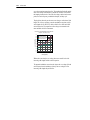
Chapter
1
Specifications & Dimensions
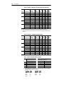
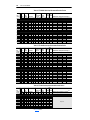
PowerFlex 70/700
Specifications
Category
Protection
Specification
200-208V 240V
380/400 480V
600V
690V
PowerFlex 70 Drive
Drive
Drive
Drive
Drive
Drive
Drive
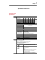
AC Input Overvoltage Trip:
247VAC 285VAC 475VAC 570VAC 690VAC
AC Input Undervoltage Trip:
120VAC 138VAC 233VAC 280VAC 345VAC
Bus Overvoltage Trip:
350VDC 405VDC 675VDC 810VDC 1013VDC
Bus Undervoltage Trip:
176VDC 204VDC 339VDC 407VDC 998VDC
Nominal Bus Voltage:
281VDC 324VDC 540VDC 648VDC 810VDC
PowerFlex 700
AC Input Overvoltage Trip:
AC Input Undervoltage Trip:
See PowerFlex 70 above
Bus Overvoltage Trip:
Bus Undervoltage Trip:
Adjustable
Nominal Bus Voltage:
See PowerFlex 70 above
All Drives
Heat Sink Thermistor:
Monitored by microprocessor overtemp trip
Drive Overcurrent Trip
Software Current Limit:
20-160% of rated current
Hardware Current Limit:
200% of rated current (typical)
Instantaneous Current Limit:
220-300% of rated current (dependent on drive rating)
Line transients:
up to 6000 volts peak per IEEE C62.41-1991
Control Logic Noise Immunity:
Showering arc transients up to 1500V peak
Power Ride-Thru:
15 milliseconds at full load
Logic Control Ride-Thru:
0.5 seconds minimum, 2 seconds typical
Ground Fault Trip:
Phase-to-ground on drive output
Short Circuit Trip:
Phase-to-phase on drive output
Agency
The drive is designed to meet the following specifications:
Certification NFPA 70 - US National Electrical Code
NEMA ICS 3.1 - Safety standards for Construction and Guide for Selection,
Installation and Operation of Adjustable Speed Drive Systems.
NEMA 250 - Enclosures for Electrical Equipment
IEC 146 - International Electrical Code.
UL and cUL Listed to UL508C and CAN/CSA-C2.2 No. 14-M91
c UL
US
Marked for all applicable European Directives (1)
EMC Directive (89/336/EEC)
Emissions
EN 61800-3 Adjustable Speed electrical power drive systems Part 3
Immunity
EN 61800-3 Second Environment, Restricted Distribution
Low Voltage Directive (73/23/EEC)
EN 60204-1 Safety of Machinery –Electrical Equipment of Machines
EN 50178 Electronic Equipment for use in Power Installations
1-2
Input/Output Ratings
Category
Specification
Environment Altitude:
Ambient Operating Temperature
without derating:
Open Type:
IP20:
NEMA Type 1:
IP56, NEMA Type 4X
Storage Temperature (all const.):
Relative Humidity:
Shock:
Vibration:
Electrical
Voltage Tolerance:
Frequency Tolerance:
Input Phases:
Control
Displacement Power Factor
PF70 - C & D Frame Drives:
PF70 - A & B Frame Drives:
PF700
Efficiency:
Max. Short Circuit Current Rating:
Using Recommended Fuse or
Circuit Breaker Type
Method:
Carrier Frequency
PF70 - A-D Frame Drives:
PF700 - 0-3 Frames:
Output Voltage Range:
Output Frequency Range:
Frequency Accuracy
Digital Input:
Analog Input:
Speed Regulation - Open Loop
with Slip Compensation:
Selectable Motor Control:
Stop Modes:
Accel/Decel:
Intermittent Overload:
Current Limit Capability:
Electronic Motor Overload
Protection
(1)
1000 m (3300 ft) max. without derating
0 to 50 degrees C (32 to 122 degrees F)
0 to 50 degrees C (32 to 122 degrees F)
0 to 40 degrees C (32 to 104 degrees F)
0 to 40 degrees C (32 to 104 degrees F)
–40 to 70 degrees C (–40 to 158 degrees F)
5 to 95% non-condensing
15G peak for 11ms duration (±1.0 ms)
0.152 mm (0.006 in.) displacement, 1G peak
–10% of minimum, +10% of maximum.
47-63 Hz.
Three-phase input provides full rating for all drives. Single-phase
operation provides 50% of rated current.
0.92 lagging (entire speed range)
0.64 lagging
TBD
97.5% at rated amps, nominal line volts.
Maximum short circuit current rating to match specified fuse/circuit
breaker capability.
Sine coded PWM with programmable carrier frequency. Ratings apply
to all drives (refer to the Derating Guidelines on page 1-3). The drive
can be supplied as 6 pulse or 12 pulse in a configured package.
2-10 kHz. Drive rating based on 4 kHz
2-10 kHz. Drive rating based on 4 kHz
0 to rated motor voltage
0 to 400 Hz.
Within ±0.01% of set output frequency.
Within ±0.4% of maximum output frequency.
±0.5% of base speed across a 40:1 speed range.
Sensorless Vector with full tuning. Standard V/Hz with full custom
capability. PF700 adds flux vector.
Multiple programmable stop modes including - Ramp, Coast, DC-Brake,
Ramp-to-Hold and S-curve.
Two independently programmable accel and decel times. Each time
may be programmed from 0 - 3600 seconds in 0.1 second increments
110% Overload capability for up to 1 minute
150% Overload capability for up to 3 seconds
Proactive Current Limit programmable from 20 to 160% of rated output
current. Independently programmable proportional and integral gain.
Class 10 protection with speed sensitive response. Investigated by U.L.
to comply with N.E.C. Article 430. U.L. File E59272, volume 12.
Applied noise impulses may be counted in addition to the standard pulse train causing erroneously high [Pulse Freq] readings.
Input/Output Ratings
Each PowerFlex Drive has normal and heavy duty torque capabilities. The
listings can be found in Tables 2.O through 2.S.
Heat Dissipation
See Watts Loss on page 2-172.
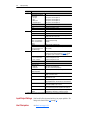
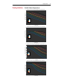
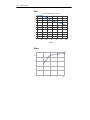
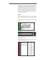
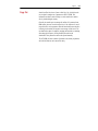
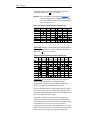
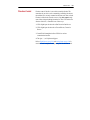
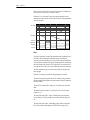
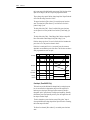
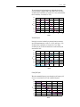
Derating Guidelines
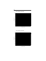
PowerFlex 70 Ambient Temperature/Load
PowerFlex70, A Frame 400V Class. Derating, Ambient Temperature and Load. Open, NEMA1, IP20.
62
Max Ambient Temperature, C
60
58
56
54
10kHz
8kHz
6kHz
4kHz
2kHz
52
50
48
40
50
60
70
% of Full Load, Amps
80
90
100
PowerFlex70, B Frame 400V Class. Derating, Ambient Temperature and Load. Open, NEMA1, IP20
Max Ambient Temperature, C
65
60
55
10kHz
8kHz
6kHz
4kHz
2kHz
50
45
40
50
60
70
% of Full Load Amps
80
90
100
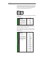
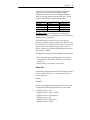
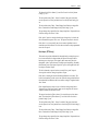
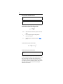
PowerFlex70, C Frame 400V Class, Derating, Ambient Temperature and Load. Open, NEMA1 and IP20
62
Max Ambient Temperature, C
60
58
56
10kHz
8kHz
6kHz
4kHz
2kHz
54
52
50
48
40
50
60
70
% of Output FLA
80
90
100
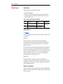
PowerFlex70, D Frame 400V Class. Derating, Ambient Temperature and Load. Open, NEMA1, IP20
60
Max Ambient Temperature, C
Derating Guidelines
55
50
10kHz
8kHz
6kHz
4kHz
2kHz
45
40
40
50
60
70
% of Full Load Amps
80
90
100
1-3
1-4
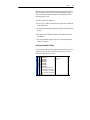
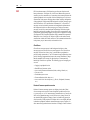
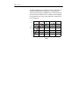
Derating Guidelines
Altitude
PowerFlex 70 Altitude Derating Factor - All Frames.
1
0.9
0.8
0.7
0.6
0.5
0.4
0.3
0.2
0.1
0
0
1000
2000
3000
4000
5000
6000
Altitude (m)
Efficiency
1
1 HP
0.5 HP
0.9
0.8
0.7
0.6
0.5
25
50
75
100
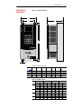
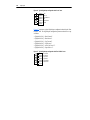
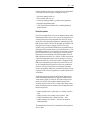
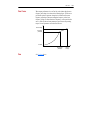
PowerFlex 70 Dimensions
PowerFlex 70
Dimensions
1-5
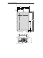
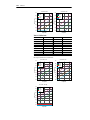
Figure 1.1 PowerFlex 70 Frames A-D
A
B
F
C D
E
Dimensions are in millimeters and (inches)
Frame
(see Table 1.A) A
A
B
C
D
121.9 (4.80)
171.2 (6.74)
185.9 (7.32)
220.4 (8.68)
B
94.2 (3.71)
122.7 (4.83)
137.6 (5.42)
169.0 (6.65)
C
211.6 (8.33)
220.2 (8.67)
285.6 (11.25)
335.7 (13.21)
D
225.8 (8.89)
234.6 (9.24)
300.0 (11.81)
350.0 (13.78)
E
5.8 (0.23)
5.8 (0.23)
5.8 (0.23)
5.8 (0.23)
F
179.8 (7.08)
179.8 (7.08)
179.8 (7.08)
180.4 (7.10)
Weight
3.56 kg (7.85 lb)
4.49 kg (9.9 lb)
7.60 kg (16.75 lb)
9.75 kg (21.5 lb)
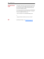
Table 1.A PowerFlex 70 Frames
240/208V AC Input
Frame ND HP
HD HP
A
0.5
0.33
1
0.75
–
–
B
2
1.5
–
–
C
3
2
5
3
D
7.5
5
10
7.5
400V AC Input
ND kW
HD kW
0.37
0.25
0.75
0.55
1.5
1.1
2.2
1.5
4
3
5.5
4
7.5
5.5
11
7.5
15
11
480V AC Input
ND HP
HD HP
0.5
0.33
1
0.75
2
1.5
3
2
5
3
7.5
5
10
7.5
15
10
20
15
600V AC Input
ND HP
HD HP
0.5
0.33
1
0.75
2
1.5
3
2
5
3
7.5
5
10
7.5
15
10
20
15
1-6
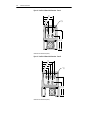
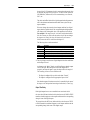
PowerFlex 70 Dimensions
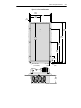
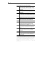
Figure 1.2 PowerFlex 70 Bottom View Dimensions - Frame A
86.4
(3.40)
80.0
(3.15)
∅ 22.2
(0.88)
41.9
(1.65)
35.6
(1.40)
99.3
(3.91)
137.4
(5.41)
Dimensions are in millimeters and (inches)
Figure 1.3 PowerFlex 70 Bottom View Dimensions - Frame B
123.7
(4.87)
104.6
(3.40)
85.6
(3.37)
66.5
(2.62)
45.5
(1.87)
∅ 22.2
(0.88)
99.3
(3.91)
Dimensions are in millimeters and (inches)
137.4
(5.41)
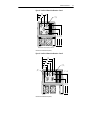
PowerFlex 70 Dimensions
Figure 1.4 PowerFlex 70 Bottom View Dimensions - Frame C
96.5
(3.80)
65.5
(2.58)
∅ 22.2
(0.88)
34.5
(1.36)
96.0 118.3 140.5
(3.78) (4.65) (5.53)
Number of fans will vary depending on drive size.
Dimensions are in millimeters and (inches)
Figure 1.5 PowerFlex 70 Bottom View Dimensions - Frame D
123.4
(4.86)
106.8
(4.20)
80.3
(3.16)
52.2
(2.06)
∅ 22.2
(0.88)
37.2
(1.46)
22.2 ∅
(0.88)
F G
102.6 140.3
(4.04) (5.52)
Dimensions are in millimeters and (inches)
1-7
1-8
PowerFlex 70 Flange Mount Dimensions
PowerFlex 70 Flange
Mount Dimensions
Drive Catalog Number
20AB2P2F
20AB4P2F
20AC1P3F / 20AD1P1F
20AC2P1F / 20AD2P1F
20AC3P5F / 20AD3P4F
20AE0P9F
20AE1P7F
20AE2P7F
20AB6P8F
20AC5P0F / 20AD5P0F
20AC8P7F / 20AD8P0F
20AE3P9F
20AE6P1F
20AB9P6F
20AB015F
20AC011F / 20AD011F
20AC015F / 20AD014F
20AE9P0F
20AE011F
20AB9P6F
20AB015F
20AC011F / 20AD011F
20AC015F / 20AD014F
20AE9P0F
20AE011F
Figure
Knockout Dimensions
Figure 1.7
Cutout Dimensions
Figure 1.11
Figure 1.8
Figure 1.12
Figure 1.9
Figure 1.13
Figure 1.10
Figure 1.14
Figure 1.6 Overall Dimensions
A
C
B
Dimensions are in millimeters and (inches)
Frame
A
B
C
D
A
156.0 (6.14)
205.2 (8.08)
219.0 (8.62)
248.4 (9.78)
B
225.8 (8.89)
234.6 (9.24)
300.0 (11.81)
350.0 (13.78)
C
178.6 (7.03)
178.6 (7.03)
178.6 (7.03)
178.6 (7.03)
PowerFlex 70 Flange Mount Dimensions
Figure 1.7 A Frame Knockout Dimensions
101.9
(4.01)
96.1
(3.78)
72.4
(2.85)
22.2 dia.
(0.87 dia.)
59.6
(2.35)
76.6
(3.02)
70.5
(2.78)
43.2
(1.70)
Dimensions are in millimeters and (inches)
Figure 1.8 B Frame Knockout Dimensions
102.7
(4.04)
130.5
(5.14)
140.6
(5.54)
92.4
(3.64)
70.9
(2.79)
22.2 dia.
(0.87 dia.)
76.6
(3.02)
65.9
(2.59)
41.4
(1.63)
Dimensions are in millimeters and (inches)
1-9
1-10
PowerFlex 70 Flange Mount Dimensions
Figure 1.9 C Frame Knockout Dimensions
111.2
(4.38)
92.2
(3.63)
73.0
(2.87)
53.1
(2.09)
22.2 dia.
(0.87 dia.)
68.7
(2.70)
40.6
(1.60)
Dimensions are in millimeters and (inches)
Figure 1.10 D Frame Knockout Dimensions
107.3
(4.22)
135.5
(5.33)
78.3
(3.08)
51.9
(2.04)
2x 22.2 dia.
(0.87 dia.)
2x 28.5 dia.
(1.12 dia.)
74.1
(2.92)
42.3
(1.67)
Dimensions are in millimeters and (inches)
PowerFlex 70 Flange Mount Dimensions
Figure 1.11 A Frame Cutout Dimensions
156.0
(6.14)
6.9
(0.27)
70.4
(2.77)
140.7
(5.54)
127.0
(5.00)
225.8
(8.89)
210.6
(8.29)
195.1
(7.68)
105.3
(4.15)
8x 4.0 +0.13 -0.03 dia.
(0.16 +.005 -.001 dia.)
4x 3.0R
(0.12R)
7.7
(0.31)
58.8
(2.31)
Dimensions are in millimeters and (inches)
1-11
1-12
PowerFlex 70 Flange Mount Dimensions
Figure 1.12 B Frame Cutout Dimensions
205.2
(8.08)
6.9
(0.27)
190.0
(7.48)
95.0
(3.74)
176.3
(6.94)
234.6
219.3 (9.24)
(8.64)
205.5
(8.09)
109.7
(4.32)
8x 4.0 +0.13 -0.03 dia.
(0.16 +.005 -.001 dia.)
4x 3.0R
(0.12R)
6.9
(0.27)
58.8
(2.31)
Dimensions are in millimeters and (inches)
PowerFlex 70 Flange Mount Dimensions
1-13
Figure 1.13 C Frame Cutout Dimensions
219.0
(8.62)
6.3
(0.25)
202.0
(7.95)
101.0
(3.98)
300.0
(11.81)
189.4
(7.46)
283.0
(11.14)
271.8
(10.70)
241.5
(9.51)
141.5
(5.57)
41.5
(1.63)
12x 4.0 ±0.13 dia.
(0.16 ±.005 dia.)
4x 3.0R
(0.12R)
5.6
(0.22)
58.8
(2.31)
Dimensions are in millimeters and (inches)
1-14
PowerFlex 70 Flange Mount Dimensions
Figure 1.14 D Frame Cutout Dimensions
248.4
(9.78)
231.4
(9.11)
190.7
(7.51)
4.5
(0.18)
40.7
(1.60)
115.7
(4.56)
350.0
(13.78)
222.4
(8.75)
333.0
(13.11)
319.8
(12.59)
271.5
(10.69)
201.5
(7.93)
131.5
(5.18)
61.5
(2.42)
14x 4.0 ±0.13 dia.
(0.16 ±.005 dia.)
4x: 3.0R
(0.12R)
6.0
(0.24)
58.8
(2.31)
Dimensions are in millimeters and (inches)
PowerFlex 70 Flange Mount Dimensions
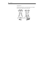
Figure 1.15 Flange Mounting
1
M4 x 8 x 25
(#10-24 x .75)
2
3
Dimensions are in millimeters and (inches)
1-15
1-16
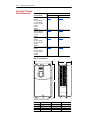
PowerFlex 700 Dimensions
PowerFlex 700
Dimensions
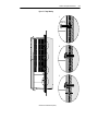
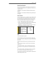
Figure 1.16 PowerFlex 700 Frames 0-3 (0 Frame Shown)
A
15.0 (0.59)
D
5.5 (0.22)
5.8 (0.23) dia.
C
E
B
CAUTION
HOT surfaces can cause severe burns
5.5 (0.22)
8.0
(0.31)
Dimensions are in millimeters and (inches).
Frame
(see Table 1.B) A
0
1
2
3
5
110.0 (4.33)
135.0 (5.31)
222.0 (8.74)
222.0 (8.74)
300.0 (11.81)
B
336.0 (13.23)
336.0 (13.23)
342.5 (13.48)
517.5 (20.37)
583.0 (22.95)
(1)
Weights include HIM and Standard I/O.
(2)
Not available at time of publication
C
200.0 (7.87)
200.0 (7.87)
200.0 (7.87)
200.0 (7.87)
270.3 (10.64)
D
80.0 (3.15)
105.0 (4.13)
192.0 (7.56)
192.0 (7.56)
225.0 (8.86)
E
320.0 (12.60)
320.0 (12.60)
320.0 (12.60)
500.0 (19.69)
625.0 (24.61) (2)
Table 1.B PowerFlex 700 Frames
208/240V AC Input
Frame ND HP HD HP
0
0.5
0.33
1
0.75
2
1.5
3
2
–
–
–
–
1
5
3
7.5
5
2
10
7.5
–
–
3
15
10
20
15
5
–
–
–
–
400V AC Input
ND kW HD kW
0.37
0.25
0.75
0.55
1.5
0.75
2.2
1.5
4
2.2
5.5
4
7.5
5.5
11
7.5
15
11
18.5
15
22
18.5
30
22
–
45
55
–
Weight (1) kg (lbs.)
Drive &
Drive
Packaging
5.22 (11.5) 8.16 (18)
7.03 (15.5) 9.98 (22)
12.52 (27.6) 15.20 (33.5)
18.55 (40.9) 22.68 (50)
480V AC Input
ND HP HD HP
0.5
0.33
1
0.75
2
1.5
3
2
5
3
7.5
5
10
7.5
15
10
20
15
25
20
30
25
40
30
–
60
75
–
(2)
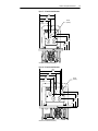
PowerFlex 700 Dimensions
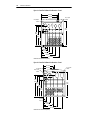
Figure 1.17 PowerFlex 700 Bottom View Dimensions – Frame 0
96.0 (3.78)
75.0 (2.95)
55.0 (2.17)
35.0 (1.38)
22.2 (0.87) Dia. – 4 Places
30.2
(1.19)
185.0
(7.28)
187.5
(7.38)
132.9
(5.23)
41.9 (1.65)
56.1 (2.21)
75.9 (2.99)
96.0 (3.78)
Dimensions are in millimeters and (inches)
Figure 1.18 PowerFlex 700 Bottom View Dimensions – Frame 1
108.5 (4.27)
87.5 (3.44)
67.5 (2.66)
47.5 (1.87)
28.6 (1.13) Dia.
22.2 (0.87) Dia.
3 Places
25.5
(1.00)
187.6
(7.39)
185.1
(7.29)
133.3
(5.25)
43.0 (1.69)
70.0 (2.76)
75.9 (2.99)
96.0 (3.78)
Dimensions are in millimeters and (inches)
1-17
1-18
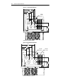
PowerFlex 700 Dimensions
Figure 1.19 PowerFlex 700 Bottom View Dimensions – Frame 2
167.5 (6.59)
156.9 (6.18)
28.7 (1.13) Dia.
3 Places
22.4 (0.88) Dia.
2 Places
184.8
(7.28)
157.5
(6.20)
150.9
(5.94)
112.1
(4.41)
39.3 (1.55)
57.2 (2.25)
72.7 (2.86)
106.0 (4.17)
139.4 (5.49)
177.4 (6.98)
Dimensions are in millimeters and (inches)
Figure 1.20 PowerFlex 700 Bottom View Dimensions – Frame 3
22.2 (0.87) Dia.
28.6 (1.13) Dia.
2 Places
105.3 (4.15)
94.7 (3.73)
37.3 (1.47) Dia.
2 Places
165.1
(6.50)
184.5
(7.26)
160.1
(6.30)
151.1
(5.95)
127.7
(5.03)
22.7 (0.89)
29.0 (1.14)
66.0 (2.60)
97.0 (3.82)
137.2 (5.40)
187.0 (7.36)
Dimensions are in millimeters and (inches)
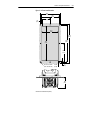
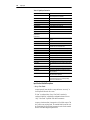
Chapter
2
Detailed Drive Operation
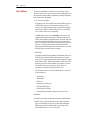
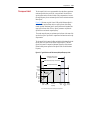
This chapter explains PowerFlex drive functions in detail. Explanations are
organized alphabetically by topic. Refer to the Table of Contents for a
listing of topics.
Accel Time
[Accel Time 1, 2]
The Accel Time parameters set the rate at which the drive ramps up its
output frequency after a Start command or during an increase in command
frequency (speed change). The rate established is the result of the
programmed Accel Time and the Minimum and Maximum Frequency, as
follows:
Maximum Frequency – Minimum Frequency
Accel Time
= Accel Rate
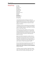
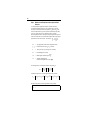
Two Accel Times exist to allow the user to change acceleration rates “on the
fly” via PLC command or Digital Input. The selection is made using the 1st
/ 2nd Accel inputs shown below or a similar pattern of Accel Time select
bits in the Logic Control word used via PLC communications.
Times are adjustable in.1 second increments from 0.0 seconds to 3600.0
seconds.
In its factory default condition, when no Accel select inputs are closed and
no Accel Time bits are “1”, the default acceleration time is Accel Time 1
and the rate is determined as above.
AC Supply Source
Considerations
PowerFlex 700 drives are suitable for use on a circuit capable of delivering
up to a maximum of 200,000 rms symmetrical amperes, 600V.
!
ATTENTION: To guard against personal injury and/or equipment
damage caused by improper fusing or circuit breaker selection, use
only the recommended line fuses/circuit breakers specified in
Tables 2.O through 2.S.
If a system ground fault monitor (RCD) is to be used, only Type B
(adjustable) devices should be used to avoid nuisance tripping.
2-2
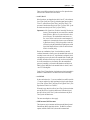
Alarms
Alarms
Alarms are indications of situations that are occurring within the drive or
application that should be annunciated to the user. These situations may
affect the drive operation or application performance. Conditions such as
Power Loss or Analog input signal loss can be detected and displayed to the
user for drive or operator action.
There are two types of alarms:
• Type 1 Alarms are conditions that occur in the drive or application that
may require alerting the operator. These conditions, by themselves, do
not cause the drive to “trip” or shut down, but they may be an indication
that, if the condition persists, it may lead to a drive fault.
• Type 2 Alarms are conditions that are caused by improper programming
and they prevent the user from Starting the drive until the improper
programming is corrected. An example would be programming one
digital input for a 2-wire type control (Run Forward) and another digital
input for a 3-wire type control (Start). These are mutually exclusive
operations, since the drive could not determine how to properly issue a
“Run” command. Because the programming conflicts, the drive will
issue a type 2 alarm and prevent Starting until the conflict is resolved.
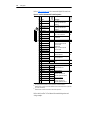
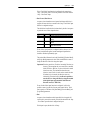
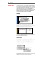
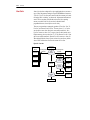
Alarm Status Indication
[Drive Alarm 1]
[Drive Alarm 2]
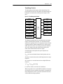
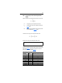
Two 16 bit Drive Alarm parameters are available to indicate the status of
any alarm conditions. Both Type 1 and Type 2 alarms are indicated.
A “1” in the bit indicates the presence of the alarm and a “0” indicates no
alarm is present
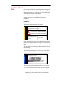
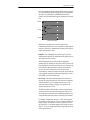
Configuration
In order for a drive alarm to be annunciated to the “outside” world, it must
first be “configured” or activated. Configuration parameters contain a
configuration bit for each Type 1 alarm. Type 2 alarms are permanently
configured to annunciate. The configuration word is a mirror image of the
Drive Alarm word; that is, the same bits in both the Drive Alarm Word and
the Alarm Configuration Word represent the same alarm.
Drive Alarm
1
1
1
1
0
0
X
X
Alarm Config
Active Inactive Inactive
Alarm Alarm Alarm
Alarms
2-3
The configuration bits act as a mask to block or pass through the alarm
condition to the active condition. An active alarm will be indicated on the
LCD HIM and will cause the drive alarm status bit to go high (“1”) in the
Drive Status word (Bit 6, parameter 209). This bit can then be linked to a
digital output for external annunciation. As default, all configuration bits
are high (“1”). Note that setting a configuration bit to “0” to “mask” an
alarm does not affect the status bit in the Drive Alarm parameter, only its
ability to annunciate the condition.
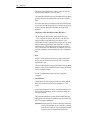
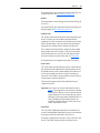
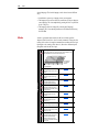
Application
A process is being controlled by a PowerFlex drive. The speed reference to
the drive is a 4 –20 mA analog signal from a sensor wired to Analog Input
1.
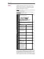
The input is configured for mA by setting the corresponding bit in [Anlg In
Config] to “1”
320 [Anlg In Config]
322
325
Selects the mode for the analog inputs.
An
a
An log In
alo 2
gI
n1
323
326
1 =Current
0 =Voltage
x =Reserved
x x x x x x x x x x x x x x 0 0
15 14 13 12 11 10 9 8 7 6 5 4 3 2 1 0
Bit #
Factory Default Bit Values
Analog In Config
0
1
Speed Ref A Sel
1
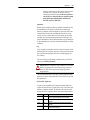
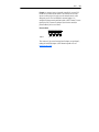
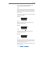
The input is scaled for 4-20 mA by setting [Analog In 1 Lo] to “4” mA and
[Analog In 1 Hi] to “20” mA.
The signal is designated as the active speed reference by setting [Speed Ref
A Sel] to its factory default value of “1”
090 [Speed Ref A Sel]
Default:
Selects the source of the speed
Options:
reference to the drive unless [Speed Ref
B Sel] or [Preset Speed 1-7] is selected.
Speed References
(1) See Appendix B for DPI port locations.
2
“Analog In 2”
1
2
3-8
9
10
11
12
13
14
15
16
17
18
19
20
21
22
23
“Analog In 1”
“Analog In 2”
“Reserved”
“MOP Level”
“Reserved”
“Preset Spd1”
“Preset Spd2”
“Preset Spd3”
“Preset Spd4”
“Preset Spd5”
“Preset Spd6”
“Preset Spd7”
“DPI Port 1”(1)
“DPI Port 2”(1)
“DPI Port 3”(1)
“DPI Port 4”(1)
“DPI Port 5”(1)
“DPI Port 6”(1)
002
091
thru
093
101
thru
107
117
thru
120
192
thru
194
213
272
273
320
361
thru
366
Alarms
By setting Speed Ref A Hi to 60 Hz and Speed ref A Lo to 0 Hz, the speed
reference is scaled to the application needs. Because of the Input scaling
and link to the speed reference, 4 mA represents minimum frequency (0
Hz.) and 20 mA represents Maximum Frequency (60 Hz.)
Scale Block
P322
20mA
P325
4mA
P091
60 Hz
P092
0 HZ
The input is configured to recognize a loss of signal and react accordingly to
the programming.
324 [Analog In 1 Loss]
327 [Analog In 2 Loss]
Default:
0
0
“Disabled”
“Disabled”
Selects drive action when an analog
Options:
signal loss is detected. Signal loss is
defined as an analog signal less than 1V
or 2mA. The signal loss event ends and
normal operation resumes when the
input signal level is greater than or equal
to 1.5V or 3mA.
0
1
2
3
4
5
6
“Disabled”
“Fault”
“Hold Input”
“Set Input Lo”
“Set Input Hi”
“Goto Preset1”
“Hold OutFreq”
091
092
The loss action is chosen as Hold Input, meaning that the last received
signal will be maintained as the speed reference.
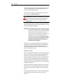
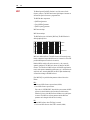
Finally, a Digital Output relay is configured to annunciate an alarm by
turning on a flashing yellow light mounted on the operator panel of the
process control area.
380 [Digital Out1 Sel]
384 [Digital Out2 Sel]
Default:
Digital Outputs
Selects the drive status that will energize Options:
a (CRx) output relay.
INPUTS & OUTPUTS
2-4
(1)Contacts shown on page 1-12 are in
drive powered state with condition not
present. For functions such as “Fault”
and “Alarm” the normal relay state is
energized and N.O. / N.C. contact wiring
may have to be reversed.
1
4
“Fault”
“Run”
381
385
1
2
3
4
5
6
7
8
9
10
11
12
13
14
15
16
17
18
19
20
21
22
23
24
25
26
“Fault”(1)
“Alarm”(1)
“Ready”
“Run”
“Forward Run”
“Reverse Run”
“Auto Restart”
“Powerup Run”
“At Speed”
“At Freq”
“At Current”
“At Torque”
“At Temp”
“At Bus Volts”
“At PI Error”
“DC Braking”
“Curr Limit”
“Economize”
“Motor Overld”
“Power Loss”
“Input 1 Link”
“Input 2 Link”
“Input 3 Link”
“Input 4 Link”
“Input 5 Link”
“Input 6 Link”
382
386
383
002
001
003
004
218
012
137
157
147
053
048
184
Alarms
2-5
While the process is normal and running from the analog input, everything
proceeds normally. However, if the wire for the analog input should be
severed or the sensor malfunction so that the 4-20mA signal is lost, the
following sequence occurs:
1. the drive will sense the signal loss
2. an active Type 1 Alarm is created and the last signal value is maintained
as the speed reference
3. the alarm activates the Digital output relay to light the alarm light for the
operator
4. The operator uses the HIM to switch the drive to Manual Control (see
Auto/Manual)
5. The operator manually brings the process to a controlled stop until the
signal loss is repaired.
Alarm Queue (PowerFlex 700 Only)
Alarms
UTILITY
A queue of 8 parameters exists that capture the drive alarms as they occur. A
sequential record of the alarm occurrences allows the user to view the
history of the eight most recent events.
262
263
264
265
266
267
268
269
[Alarm 1 Code]
[Alarm 2 Code]
[Alarm 3 Code]
[Alarm 4 Code]
[Alarm 5 Code]
[Alarm 6 Code]
[Alarm 7 Code]
[Alarm 8 Code]
A code that represents a drive alarm.
The codes will appear in the order they
occur (first 4 alarms in – first 4 out alarm
queue). A time stamp is not available with
alarms.
Default:
Read Only
Min/Max: 0/256
Display: 1
261
2-6
Analog Inputs
Analog Inputs
Possible Uses of Analog Inputs
The analog inputs provide data that can be used for the following purposes:
• Provide a value to [Speed Ref A] or [Speed Ref B].
• Provide a trim signal to [Speed Ref A] or [Speed Ref B].
• Provide a reference when the terminal block has assumed manual control
of the reference
• Provide the reference and feedback for the PI loop. See Process PI
Loop on page 2-116.
• Provide an external and adjustable value for the current limit and DC
braking level
• Enter and exit sleep mode.
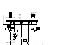
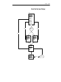
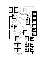
Analog Input Configuration
[Anlg In Config]
[Current Lmt Sel] allows an analog input to control the set point while [DC
Brk Levl Sel] allows an analog input to define the DC hold level used when
Ramp-to-Stop, Ramp-to-Hold, or Brake-to-Stop is active.
To provide local adjustment of a master command signal or to provide
improved resolution the input to analog channel 1 or 2 can be defined as a
trim input. Setting [Trim In Select] allows the selected channel to modify
the commanded frequency by 10%.The speed command will be reduced by
10% when the input level is at [Anlg In x Lo] with it linearly increasing to
10% above command at [Anlg In xHi].
Feedback can be used to control an operation using the “Process PI”
(proportional-integral) feature of the control. In this case one signal, defined
using [PI Reference Sel], provides a reference command and a second,
defined using [PI Feedback Sel], provides a feedback signal for frequency
compensation. Please refer to the Process PI Loop on page 2-116 for details
on this mode of operation.
Analog In 1 Lo
Input/Output
Analog In 1 Hi
Volts or mA
Analog Input
1 Scale
Parameter
Cal Analog 1
Analog In 2 Lo
Processing
Analog In 2 Hi
Speed Ref A Sel
Analog Input
2 Scale
Speed Ref B Sel
Volts or mA
Trim In Select
Selection/Control
Cal Analog 2
TB Man Ref Sel
PI Reference Sel
PI Feedback Sel
Current Lmt Sel
DC Brk Levl Sel
Sleep-Wake Ref
Speed Ref A Lo
Speed Ref A Hi
Speed Ref B Lo
Ref A
Scale/Limit
Speed Ref B Hi
Trim Lo
Ref B
Scale/Limit
Sleep Level
Brake Level
Scale/Limit
Wake Level
Sleep Level
Compare
Trim Hi
Trim
Scale/Limit
Hz
TB Manual
Scale/Limit
Trim Out Sel
PI
Reference
Scale/Limit
PI Feedback
Scale/Limit
+
Hz
Reference A
Hz
Reference B
Hz
TB Manual
%
PI Reference
%
PI Feedback
% Rated
Current
Current Limit
% Rated
Current
DC Brake
Sleep/
Wake
Analog Inputs
Current Limit
Scale/Limit
+
Sleep/Wake
2-7
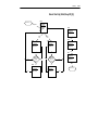
2-8
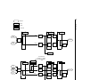
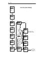
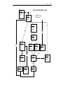
Input/Output
Analog Inputs
Parameter
Processing
Selection/Control
Anlg In 1 Loss
Anlg In Config
0-10v
Analog 1
Voltage
Unipolar
Cal 1
Loss
Detect
Anlg In Sqr Root
Limit
0-10V
Cal Analog 1
ADC
Analog 1
Current
0-20mA
Current
Cal 1
Loss
Detect
Limit
4-20mA
Square
Root
Analog In1 Value
Analog In 2 Lo
Anlg In Config
Analog 2
Current
ADC
Anlg In 2 Loss
Analog In 2 Hi
0-10v
Unipolar
Cal 2
(voltage)
-10v - +10v
Bipolar
Cal 2
(current)
0-20mA
Current
Cal 2
Analog 2
Unipolar
Analog 2
Bipolar
Note: If either of these
parameters is < 0, input will go
into bipolar mode, otherwise
unipolar.
Loss
Detect
Anlg In Sqr Root
Limit
0-10V
Limit
-10V to
10V
Loss
Detect
Limit
4-20mA
Analog In2 Value
Cal Analog 2
Square
Root
Analog Inputs
2-9
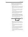
Scaling Blocks
[Analog In Hi]
[Analog In Lo]
A scaling operation is performed on the value read from an analog input in
order to convert it to units usable for some particular purpose. The user
controls the scaling by setting parameters that associate a low and high
point in the input range (i.e. in volts or mA) with a low and high point in the
target range (e.g. reference frequency).
Two sets of numbers may be used to specify the analog input scaling. One
set (called the “input scaling points”) defines low and high points in terms
of the units read by the input hardware, i.e. volts or mA.
The second set of numbers (called the “output scaling points”) used in the
analog input scaling defines the same low and high points in units
appropriate for the desired use of the input. For instance, if the input is to be
used as a frequency reference, this second set of numbers would be entered
in terms of Hz. For many features the second set of numbers is fixed. The
user sets the second set for speed and reference trim.
An analog input or output signal can represent a number of different
commands. Typically an analog input is used to control output frequency,
but it could control frequency trim or current limit. An analog output
typically is a frequency indication, but it could represent output current,
voltage, or power. For this reason this document defines an analog signal
level as providing a “command” value rather than a “frequency.” However
when viewing a command value it is presented as a frequency based on the
[Minimum Speed] and [Maximum Freq] settings.
The 0-10 volt input scaling can be adjusted using the following parameters:
• [Analog In x Lo]
• [Analog In x Hi]
Analog Inputs
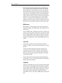
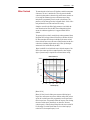
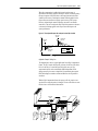
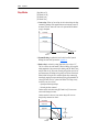
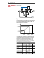
Configuration #1:
•
•
•
•
•
[Speed Ref A Sel] = “Analog In 1”
[Minimum Speed] = 0 Hz
[Maximum Speed] = 60 Hz
[Analog In 1 Lo] = 0%
[Analog In 1 Hi] = 100%
This is the default setting, where minimum input (0 volts) represents
[Minimum Speed] of 0 Hz and maximum input (10 volts) represents
[Maximum Speed] of 60 Hz.
12
10
Input Volts
2-10
Config 1
8
6
4
2
0
6
12
18
24
30
36
42
48
54
60
Output Hertz
Scaling Block
[Speed Reference A Sel] = “Analog In 1”
[Analog In 1 Lo]
[Minimum Speed]
0V
0 Hz
[Maximum Speed]
[Analog In 1 Hi]
10V
60 Hz
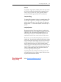
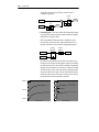
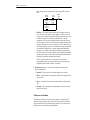
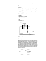
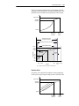
Configuration #2:
•
•
•
•
•
[Speed Ref A Sel] = “Analog In 1”
[Minimum Speed] = 0 Hz
[Maximum Speed] = 30 Hz
[Analog In 1 Lo] = 0%
[Analog In 1 Hi] = 100%
This is an application that only requires 30 Hz as a maximum output
frequency, but is still configured for full 10 volt input. The result is that the
resolution of the input has been doubled, providing only 3 Hz change per
input volt (Configuration #1 is 6 Hz/Volt).
Analog Inputs
12
Input Volts
10
Config 2
8
6
4
2
0
6
12
18
24
30
36
42
48
54
60
Output Hertz
Scaling Block
[Speed Reference A Sel] = “Analog In 1”
[Analog In 1 Lo]
[Minimum Speed]
0V
0 Hz
[Maximum Speed]
[Analog In 1 Hi]
10V
30 Hz
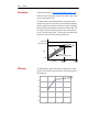
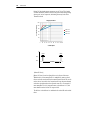
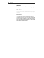
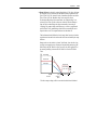
Configuration #3:
•
•
•
•
•
[Speed Ref A Sel] = “Ana In 1”
[Minimum Speed] = 0 Hz.
[Maximum Speed] = 60 Hz.
[Analog In 1 Lo] = 20%
[Analog In 1 Hi] = 100%
This configuration is referred to as offset. In this case, a 2-10 volt input
signal provides 0-60 Hz output, providing a 2 volt offset in the speed
command.
12
Input Volts
10
Config 3
8
6
4
2
0
6
12
18
24
30
36
Output Hertz
Scaling Block
[Speed Reference A Sel] = “Analog In 1”
[Analog In 1 Lo]
[Minimum Speed]
2V
0 Hz
[Analog In 1 Hi]
[Maximum Speed]
10V
60Hz
42
48
54
60
2-11
Analog Inputs
Configuration #4:
•
•
•
•
[Minimum Speed] = 0 Hz.
[Maximum Speed] = 60 Hz.
[Analog In 1 Lo] = 100%
[Analog In 1 Hi] = 0%
This configuration is used to invert the operation of the input signal. Here,
maximum input (100% of 10 Volts = 10 Volts) represents [Minimum Speed]
of 0 Hz and minimum input (0% of 10 Volts = 0 Volts) represents
[Maximum Speed] of 60 Hz.
12
10
Input Volts
2-12
Config 4
8
6
4
2
0
6
12
18
24
30
36
42
48
54
60
Output Hertz
Scaling Block
[Speed Reference A Sel] = “Analog In 1”
[Analog In 1 Lo]
[Minimum Speed]
10V
0 Hz
[Maximum Speed]
[Analog In 1 Hi]
0V
60Hz
Configuration #5:
•
•
•
•
[Minimum Speed] = 0 Hz.
[Maximum Speed] = 60 Hz.
[Analog In 1 Lo] = 0%
[Analog In 1 Hi] = 50%
This configuration is used when the input signal is 0-5 volts. Here,
minimum input (0% of 10 Volts = 0 Volts) represents [Minimum Speed] of
0 Hz and maximum input (50% of 10 Volts = 5 Volts) represents [Maximum
Speed] of 60 Hz. This allows full scale operation from a 0-5 volt source.
Analog Inputs
2-13
6
Input Volts
5
Config 5
4
3
2
1
0
6
12
18
24
30
36
42
48
54
60
Output Hertz
Scaling Block
[Speed Reference A Sel] = “Analog In 1”
[Analog In 1 Lo]
[Minimum Speed]
0V
0 Hz
[Maximum Speed]
[Analog In 1 Hi]
5V
60Hz
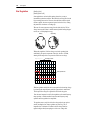
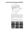
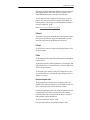
Square Root
[Anlg In Sqr Root]
For both analog inputs, the user can enable a square root function for an
analog input through the use of [Analog In Sq Root]. The function should
be set to enabled if the input signal varies with the square of the quantity
(i.e. drive speed) being monitored.
If the mode of the input is bipolar voltage (-10v to 10v), then the square root
function will return 0 for all negative voltages.
The square root function is scaled such that the input range is the same as
the output range. For example, if the input is set up as a unipolar voltage
input, then the input and output ranges of the square root function will be 0
to 10 volts, as shown in figure below.
Output (Volts)
10
8
6
4
2
0
2
4
6
Input (Volts)
8
10
2-14
Analog Inputs
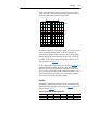
Signal Loss
[Analog In 1, 2 Loss]
Signal loss detection can be enabled for each analog input. The [Analog In
x Loss] parameters control whether signal loss detection is enabled for each
input and defines what action the drive will take when loss of any analog
input signal occurs.
One of the selections for reaction to signal loss is a drive fault, which will
stop the drive. All other choices make it possible for the input signal to
return to a usable level while the drive is still running.
•
•
•
•
•
Hold input
Set input Lo
Set input Hi
Goto Preset 1
Hold Output Frequency
Value
0
1
2
3
4
5
6
Action on Signal Loss
Disabled
Fault
Hold input (continue to use last frequency command.)
Set Input Hi - use [Minimum Speed] as frequency command.
Set Input Lo - use [Maximum Speed] as frequency command.
use [Preset 1] as frequency command.
Hold Out Freq (maintain last output frequency)
If the input is in current mode, 4 mA is the normal minimum usable input
value. Any value below 3.2 mA will be interpreted by the drive as a signal
loss, and a value of 3.8 mA will be required on the input in order for the
signal loss condition to end.
If the input is in unipolar voltage mode, 2V is the normal minimum usable
input value. Any value below 1.6 volts will be interpreted by the drive as a
signal loss, and a value of 1.9 volts will be required on the input in order for
the signal loss condition to end.
No signal loss detection is possible while an input is in bipolar voltage
mode. The signal loss condition will never occur even if signal loss
detection is enabled.
Trim
An analog input can be used to trim the active speed reference (Speed
Reference A/B). If analog is chosen as a trim input, two scale parameters
are provide to scale the trim reference. The trim is a +/- value which is
summed with the current speed reference. See also Speed Reference on
page 2-144.
•
•
•
•
[Trim In Select]
[Trim Out Select]
[Trim Hi]
[Trim Lo]
Analog Inputs
2-15
Value Display
Parameters are available in the Monitoring Group to view the actual value
of an analog input regardless of its use in the application. Whether it is a
current limit adjustment, speed reference or trim function, the incoming
value can be read via these parameters.
Metering
The value displayed includes the input value plus any factory hardware
calibration value, but does not include scaling information programmed by
the user (i.e. [Analog In 1 Hi/Lo]). The units displayed are determined by
the associated configuration bit (Volts or mA)
016 [Analog In1 Value]
017 [Analog In2 Value]
Value of the signal at the analog inputs.
Default:
Read Only
Min/Max: 0.000/20.000 mA
–/+10.000V
Display: 0.001 mA or 0.001 Volt
Cable Selection
Important points to remember:
• Always use copper wire.
• Wire with an insulation rating of 600V or greater is recommended.
• Control and signal wires should be separated from power wires by at
least 0.3 meters (1 foot).
Important: I/O terminals labeled “–” or “Common” are not referenced to
ground and are designed to greatly reduce common mode
interference. Grounding these terminals can cause signal noise.
!
!
ATTENTION: Configuring an analog input for 0-20mA operation
and driving it from a voltage source could cause component damage. Verify proper configuration prior to applying input signals.
ATTENTION: Hazard of personal injury or equipment damage
exists when using bipolar input sources. Noise and drift in sensitive
input circuits can cause unpredictable changes in motor speed and
direction. Use speed command parameters to help reduce input
source sensitivity.
Table 2.A Recommended Signal Wire
Signal
Type
Wire Type(s)
Standard
Belden 8760/9460(or equiv.)
Analog I/O
Belden 8770(or equiv.)
Encoder/
Pulse I/O
EMC
Compliance
Description
0.750 mm2 (18AWG), twisted
pair, 100% shield with drain (1).
0.750 mm2 (18AWG), 3 cond.,
shielded for remote pot only.
Less than or equal to 30 m (98 ft.) 0.196 mm2 (24AWG),
– Belden 9730 (or equiv.)
individually shielded.
Greater than 30 m (98 ft.) –
0.750 mm2 (18AWG), twisted
Belden 9773(or equiv.)
pair, shielded.
Refer to EMC Instructions on page 2-37 for details.
Minimum
Insulation Rating
300V,
60 degrees C
(140 degrees F)
(1) If the wires are short and contained within a cabinet which has no sensitive circuits, the use of shielded wire
may not be necessary, but is always recommended.
Analog Inputs
Refer to Table 2.J on page 2-46 for recommended digital I/O control wire.
No. Signal
1 Anlg Volts In 1 (–)
1
16
32
(1)
2
Anlg Volts In 1 (+)
3
4
Anlg Volts In 2 (–)
Anlg Volts In 2 (+)
5
6
7
8
9
10
11
12
13
14
15
16
17
18
19
20
21
22
23
24
25
26
27
28
29
30
31
32
Pot Common
–
Anlg Volts Out 1 (–) (1)
Anlg Volts Out 1 (+)
Anlg Current Out 1 (–) (1)
Anlg Current Out 1 (+)
Reserved for Future Use
Digital Out 1 – N.C.
Fault
Digital Out 1 Common
Digital Out 1 – N.O.
Digital Out 2 – N.C.
Alarm
Digital Out 2 Common
Digital Out 2 – N.O.
Anlg Current In 1 (–) (1)
Anlg Current In 1 (+)
Anlg Current In 2 (–) (1)
Anlg Current In 2 (+)
–10V Pot Reference –
+10V Pot Reference –
Reserved for Future Use
+24VDC
–
Digital In Common
–
24V Common
–
Digital In 1
Stop - CF
Digital In 2
Start
Digital In 3
Jog
Digital In 4
Speed Sel 1
Digital In 5
Speed Sel 2
Digital In 6
Speed Sel 3
(1)
Description
Isolated (2), bipolar, differential, ±10V,
11 bit & sign, 100k ohm input
impedance.
Isolated (3), bipolar, differential, ±10V,
11 bit & sign, 100k ohm input
impedance.
For (+) and (–) 10V pot references.
Bipolar, differential, ±10V, 11 bit &
sign, 2k ohm minimum load.
Related
Param.
Figure 2.1 PowerFlex 700 Standard I/O Terminal Designations
Factory
Default
2-16
320 329
338 346
4-20mA, 11 bit & sign, 500 ohm
maximum load.
Resistive Load
Rating: 8A at 250V AC/30V DC
Min. Load: 10mA
Inductive Load
Rating: 2A at 250V AC/30V DC
Min. Load: 10mA
380 387
Isolated (2), 4-20mA, 11 bit & sign, 100 320 ohm input impedance.
329
Isolated (3), 4-20mA, 11 bit & sign, 100
ohm input impedance.
2k ohm minimum, 15mA maximum
load.
Drive supplied power for logic inputs.
150mA maximum Load.
115V AC, 50/60 Hz
Opto isolated (250V)
Low State: less than 30V AC
High State: greater than 100V AC
24V AC/DC, 50/60 Hz
Opto isolated (250V)
Low State: less than 5V AC
High State: greater than 20V AC
361 366
(1) These inputs/outputs are dependant on a number of parameters. See “Related Parameters.”
(2) Differential Isolation - External source must be maintained at less than 160V with respect to PE. Input provides
high common mode immunity.
(3) Differential Isolation - External source must be less than 10V with respect to PE.
Refer to the PowerFlex 70 User Manual for terminal designations and
wiring examples.
Analog Inputs
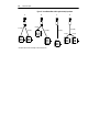
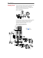
I/O Wiring Examples (PowerFlex 700 shown)
Input/Output
Connection Example (3)
(1)
Potentiometer
Potentiometer
10k Ohm Pot.
Recommended
1
(2k Ohm Minimum)
2
Joystick (1)
±10V Input - 100k
5
ohm input
impedance.
Joystick
3
5
22
Analog Input
Voltage - Bipolar (1)
±10V Input - 100k
ohm input
impedance.
3
4-20 mA Input - 100
4
ohm input
impedance
Analog/Digital
Voltage
Output
±10V Output - Can
drive a 10k ohm
load (25 mA short
circuit current limit).
+
–
21
22
Current - Unipolar
17
18
Current
–
+
Logic
Power Source
+
6
7
–
8
9
or
11
12
13
14
15
16
2 Wire Control (2) - 24VDC Internal Supply (4) 24VDC External Supply 115V External Source
Non-Reversing
Common +24V
Neutral 115V
24
Requires 2-wire
25
25
25
functions only ([Dig26
27
27
27
ital In1 Sel]). Using
Stop-Run
3-wire selections
Stop-Run
Stop-Run
will cause a type 2
alarm.
3 Wire Control
24VDC Internal Supply (4) 24VDC External Supply 115V External Source
Requires only
Common +24V
24
Neutral 115V
3-wire functions
25
25
25
26
([Digital In1 Sel]).
Stop
Stop
27
Including 2-wire
Stop
27
27
28
28
selections will
28
cause a type 2
Start
alarm.
Start
Start
(1) Refer to the Attention statement on page 2-15 for important bipolar wiring information.
(2) Important: Programming inputs for 2 wire control deactivates all HIM Start buttons.
(3) Examples show hardware wiring only. Refer to page 2-16 for parameters that must be adjusted.
(4) If desired, a User Supplied 24V DC power source can be used. Refer to the “External” example.
2-17
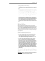
Analog Outputs
Explanation
Each drive has one or more analog outputs that can be used to annunciate a
wide variety of drive operating conditions and values.
The user selects the source for the analog output by setting [Analog Outx
Sel].
342 [Analog Out1 Sel]
Analog Outputs
Analog Outputs
INPUTS & OUTPUTS
2-18
Selects the source of the value that
drives the analog output.
Default:
0
Options:
See Table
“Output Freq”
001
002
003
004
005
007
006
012
135
136
137
138
Configuration
The PowerFlex 70 standard I/O analog output is permanently configured as
a 0 -10 volt output. The output has 10 bits of resolution yielding 1024 steps.
The analog output circuit has a maximum 1.3% gain error and a maximum
7 mV offset error. For a step from minimum to maximum value, the output
will be within 0.2% of its final value after 12ms.
The PowerFlex 700 standard I/O analog output is permanently configured
as a 0 -10 volt output. The output has 10 bits of resolution yielding 1024
steps. The analog output circuit has a maximum 1.3% gain error and a
maximum 100 mV offset error. For a step from minimum to maximum
value, the output will be within 0.2% of its final value after 12ms.
Absolute
Certain quantities used to drive the analog output are signed, i.e. the
quantity can be both positive and negative. The user has the option of
having the absolute value (value without sign) of these quantities taken
before the scaling occurs. Absolute value is enabled separately for each
analog output via the bitmapped parameter [Anlg Out Absolut].
Important: If absolute value is enabled but the quantity selected for output
is not a signed quantity, then the absolute value operation will
have no effect.
Scaling Blocks
The user defines the scaling for the analog output by entering analog output
voltages into two parameters, [Analog Out1 Lo] and [Analog Out1 Hi].
These two output voltages correspond to the bottom and top of the possible
range covered by the quantity being output, as described in Table 2.B, and
the output voltage will vary linearly with the quantity being output. The
analog output voltage will not go outside the range defined by [Analog Out1
Lo] and [Analog Out1 Hi].
Analog Outputs
2-19
Table 2.B Analog Output Scaling Ranges
Quantity
Output Frequency
Commanded
Frequency
Output Current
Output Torque Current
Output Flux Current
Output Power
Output Voltage
Dc Bus Voltage
PI Reference
PI Feedback
PI Error
PI Output
[Analog Outx Lo]
Corresponds to:
(Absolute Value Disabled)
-[Maximum Freq]
-[Maximum Freq]
[Analog Outx Lo]
Corresponds to:
(Absolute Value Enabled)
0 Hz
0 Hz
[Analog Outx Hi]
Corresponds to:
[Maximum Freq]
[Maximum Freq]
0 Amps
-200% of drive rated current
0 Amps
0 kW
0V
0V
-100%
-100%
-100%
-100%
0 Amps
0 Amps
0 Amps
0 kW
0V
0V
0%
0%
0%
0%
200% of drive rated current
200% of drive rated current
200% of drive rated current
200% of drive rated power
120% of drive rated voltage
200% of drive rated voltage
100%
100%
100%
100%
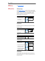
Analog Output Configuration Examples
This section gives a few examples of valid analog output configurations and
describes the behavior of the output in each case.
Example 1 -- Unsigned Output Quantity
• [Analog Out1 Sel] = “Output Current”
• [Analog Out1 Lo] = 1 volt
• [Analog Out1 Hi] = 9 volts
10V
[Analog Out1 Hi]
Output Current vs.
Analog Output Voltage
Analog
Output Voltage
Marker Lines
[Analog Out1 Lo]
0V
0%
200%
Output Current
Note that analog output value never goes outside the range defined by
[Analog Out1 Lo] and [Analog Out1 Hi], even if output current is beyond
the range defined in Table 2.B. This is true in all cases, including all the
following examples.
Example 2 -- Unsigned Output Quantity, Negative Slope
• [Analog Out1 Sel] = “Output Current”
• [Analog Out1 Lo] = 9 volts
• [Analog Out1 Hi] = 1 volts
This example shows that you can have [Analog Out1 Lo] greater than
[Analog Out1 Hi]. The result is a negative slope on the scaling from original
quantity to analog output voltage. Negative slope could also be applied to
any of the other examples in this section.
2-20
Analog Outputs
10V
[Analog Out1 Lo]
Output Current vs.
Analog Output Voltage
Analog
Output Voltage
Marker Lines
[Analog Out1 Hi]
0V
0%
200%
Output Current
Example 3 – Signed Output Quantity, Absolute Value Enabled
• [Analog Out1 Sel] = “Output Torque Current”
• [Analog Out1 Lo] = 1 volt
• [Analog Out1 Hi] = 9 volts
• [Anlg Out Absolut] set so that absolute value is enabled for output 1.
10V
[Analog Out1 Hi]
Output Torque Current vs.
Analog Output Voltage
Analog
Output Voltage
Marker Lines
[Analog Out1 Lo]
0V
200%
0%
200%
Output Torque Current
Example 4 – Signed Output Quantity, Absolute Value Disabled
• [Analog Out1 Sel] = “Output Torque Current”
• [Analog Out1 Lo] = 1 volt
• [Analog Out1 Hi] set to 9 volts
• [Anlg Out Absolut] set so that absolute value is disabled for output 1.
10V
[Analog Out1 Hi]
Output Torque Current vs.
Analog Output Voltage
Analog
Output Voltage
Marker Lines
[Analog Out1 Lo]
0V
200%
0%
200%
Output Torque Current
Filtering
Software filtering will be performed on the analog outputs for certain signal
sources, as specified in Table 2.C. “Filter A” is one possible such filter, and
it is described later in this section. Any software filtering is in addition to
any hardware filtering and sampling delays.
Analog Outputs
2-21
Table 2.C Software Filters
Quantity
Output Frequency
Commanded Frequency
Output Current
Output Torque Current
Output Flux Current
Output Power
Output Voltage
DC Bus Voltage
PI Reference
PI Feedback
PI Error
PI Output
Filter
No extra filtering
No extra filtering
Filter A
Filter A
Filter A
Filter A
No extra filtering
Filter A
No extra filtering
No extra filtering
No extra filtering
No extra filtering
Analog output software filters are specified in terms of the time it will take
the output of the filter to move from 0% to various higher levels, given an
instantaneous step in the filter input from 0% to 100%. The numbers
describing filters in this document should be considered approximate; the
actual values will depend on implementation.
Filter A is a single pole digital filter with a 162ms time constant. Given a
0% to 100% step input from a steady state, the output of Filter A will take
500ms to get to 95% of maximum, 810 ms to get to 99%, and 910 ms to get
to 100%.
2-22
Auto / Manual
Auto / Manual
The intent of Auto/Manual is to allow the user to override the selected
reference (referred to as the “auto” reference) by either toggling a button on
the programming terminal (HIM), or continuously asserting a digital input
that is configured for Auto/Manual.
• “Alt” Function on the HIM
By toggling the “Alt” and “Auto/Man” function on the HIM, the user can
switch the speed reference back and forth between the active “Auto”
source (per drive programming and inputs) and the HIM requesting the
manual control. “Manual” switches the Reference Source to the HIM,
“Auto” switches it back to drive programming.
The HIM manual reference can be preloaded from the auto source by
enabling the [Man Ref Preload] parameter. With the preload function
enabled, when the HIM requests Manual control, the current value of the
auto source is loaded into the HIM reference before manual control is
granted. This allows the manual control to begin at the same speed as the
auto source, creating a smooth transition. If the preload function is
disabled, the speed will ramp to whatever manual reference was present
in the HIM at the time manual control was granted.
• Digital Input
By toggling the digital input programmed as Auto/Manual, the user can
switch the speed reference back and forth between the active “Auto”
source (per drive programming and inputs) and the designated Terminal
Block manual reference. When this digital input is asserted, the TB will
attempt to gain exclusive control (Manual) of the reference. If granted
control of the reference, the specific source for the reference is
determined by the parameter TB manual reference select.
The TB manual reference is selected in [TB Man Ref Sel]. The choices
for this parameter are:
– Analog Input 1
– Analog Input 2
– MOP Level
– Analog Input 3 (PF700 Only)
– Pulse Input (PF700 Only)
– Encoder input (PF700 Only)
– Releasing this input sends the control back to the Auto source.
General Rules
The following rules apply to the granting and releasing of Manual control:
1. Manual control is requested through a one-time request (Auto/Man
toggle, not continuously asserted). Once granted, the terminal holds
Manual control until the Auto/Man button is pressed again, which
releases Manual control (i.e. back to Auto mode).
Auto / Manual
2-23
2. Manual control can only be granted to the TB or to a programming
terminal (e.g. HIM) if Manual control is not already being exercised by
the TB or another programming terminal at the time.
3. Manual control can only be granted to a terminal if no other device has
Local control already asserted (i.e. no other device has ownership of the
Local control function).
4. A HIM (or TB) with Manual control active can have it taken away if
another DPI port requests, and is granted Local control. In this case
when Local control is released the drive will not go back to Manual
control, Manual control must be again requested (edge based request, see
1. above). This is true for both the HIM and the TB (i.e. if the TB switch
was in the Manual position it must be switched to Auto and back to
Manual to get Manual control again).
5. The status indicator (point LED on LED HIM & Text on LCD HIM) will
indicate when that particular terminal has been granted Manual control,
not the fact any terminal connected has Manual control and not the fact
that the particular terminal has simply asked for Manual control.
6. When Manual control is granted, the drive will latch and save the current
reference value prior to entering Manual. When Manual control is then
released the drive will use that latched reference for the drive until
another DPI device arbitrates ownership and changes the reference to a
different value.
7. If a terminal has Manual control and clears its DPI reference mask
(disallows reference ownership), then Manual control will be released.
By extension, if the drive is configured such that the HIM can not select
the reference (via reference mask setting), then the drive will not allow
the terminal to acquire Manual control.
8. If a terminal has Manual control and clears its DPI logic mask (allowing
disconnect of the terminal), then Manual control will be released. By
extension if the drive is configured such that the HIM can be unplugged
(via logic mask setting), then the drive will not allow the terminal to
acquire Manual control. The disconnect also applies to a DPI HIM that
executes a soft “Logout.”
9. If a com loss fault occurs on a DPI that has Manual control, then Manual
control will be released as a consequence of the fault (on that port which
had Manual control).
10.There will be no way to request and hence no support of the Auto/
Manual feature on old SCANport based HIMs.
11.You can not acquire Manual control if you are already an assigned
source for the DPI port requesting Manual.
12.When a restore factory defaults is performed Manual control is aborted.
Auto Restart (Reset/Run)
The Auto Restart feature provides the ability for the drive to automatically
perform a fault reset followed by a start attempt without user or application
intervention. This allows remote or “unattended” operation. Only certain
faults are allowed to be reset. Certain faults (Type 2) that indicate possible
drive component malfunction are not resettable.
Caution should be used when enabling this feature, since the drive will
attempt to issue its own start command based on user selected
programming.
Configuration
This feature is configured through two user parameters
174 [Auto Rstrt Tries]
Default:
0
175
Sets the maximum number of times the Min/Max: 0/9
drive attempts to reset a fault and restart. Display: 1
!
ATTENTION: Equipment damage and/or personal injury may result
if this parameter is used in an inappropriate application. Do Not use
this function without considering applicable local, national and
international codes, standards, regulations or industry guidelines.
175 [Auto Rstrt Delay]
Sets the time between restart attempts
when [Auto Rstrt Tries] is set to a value
other than zero.
Default:
1.0 Secs
174
Min/Max: 0.5/30.0 Secs
Display: 0.1 Secs
Setting [Auto Rstrt Tries] to a value greater than zero will enable the Auto
Restart feature. Setting the number of tries equal to zero will disable the
feature.
The [Auto Rstrt Delay] parameter sets the time, in seconds, between each
reset/run attempt.
The auto-reset/run feature provides 2 status bits in [Drive Status 2] – an
active status, and a countdown status.
210 [Drive Status 2]
Read Only
209
DP
I
Mo at 50
to 0
Bu r Ov k
s F er
Cu req ld
rr
R
Au Lim eg
to it
Au Rst
toR Ac
st t
Ctd
n
Au
toT
DC un
Br ing
Sto aki
p n
Jo ping g
gg
Ru ing
nn
Ac ing
tiv
Re e
ad
y
Present operating condition of the drive.
UTILITY
Auto Restart (Reset/
Run)
Diagnostics
2-24
x x 0 0 0 0 0 0 x 0 0 0 0 0 0 0
15 14 13 12 11 10 9 8 7 6 5 4 3 2 1 0
1 =Condition True
0 =Condition False
x =Reserved
Bit #
The typical steps performed in an Auto-Reset/Run cycle are as follows:
1. The drive is running and an auto-resettable fault occurs, tripping the
drive.
2. After the number of seconds in [Auto Rstrt Delay], the drive will
automatically perform an internal Fault Reset, resetting the faulted
condition.
Auto Restart (Reset/Run)
2-25
3. The drive will then issue an internal Start command to start the drive.
4. If another auto-resettable fault occurs the cycle will repeat itself up to the
number of attempts set in [Auto Rstrt Tries].
5. If the drive faults repeatedly for more than the number of attempts set in
[Auto Rstrt Tries] with less than five minutes between each fault, the
auto-reset/run is considered unsuccessful and the drive remains in the
faulted state.
6. Aborting an Auto-Reset/Run Cycle (see Aborting an Auto-Reset/Run
Cycle for details).
7. If the drive remains running for five minutes or more since the last reset/
run without a fault, or is otherwise stopped or reset, the auto-reset/run is
considered successful. The entire process is reset to the beginning and
will repeat on the next fault.
Beginning an Auto-Reset/Run Cycle
The following conditions must be met when a fault occurs for the drive to
begin an auto-reset/run cycle.
• The fault must be defined as an auto-resettable fault
• [Auto Rstrt Tries] setting must be greater than zero.
• The drive must have been running, not jogging, not autotuning, and not
stopping, when the fault occurred. (Note that a DC Hold state is part of a
stop sequence and therefore is considered stopping.)
Aborting an Auto-Reset/Run Cycle
During an auto-reset/run cycle the following actions/conditions will abort
the reset/run attempt process.
• Issuing a stop command from any source. (Note: Removal of a 2-wire
run-fwd or run-rev command is considered a stop assertion).
• Issuing a fault reset command from any source.
• Removal of the enable input signal.
• Setting [Auto Rstrt Tries] to zero.
• The occurrence of a fault which is not auto-resettable.
• Removing power from the drive.
• Exhausting an Auto-Reset/Run Cycle
After all [Auto Rstrt Tries] have been made and the drive has not
successfully restarted and remained running for five minutes or more, the
auto-reset/run cycle will be considered exhausted and therefore
unsuccessful. In this case the auto-reset/run cycle will terminate and an
additional fault, “Auto Rstrt Tries” (Auto Restart Tries) will be issued if bit
5 of [Fault Config 1] = “1.”
2-26
Bus Regulation
Bus Regulation
[Bus Reg Gain]
[Bus Reg Mode A, B]
Some applications, such as the hide tanning shown here, create an
intermittent regeneration condition. When the hides are being lifted (on the
left), motoring current exists. However, when the hides reach the top and
fall onto a paddle, the motor regenerates power back to the drive, creating
the potential for a nuisance overvoltage trip.
When an AC motor regenerates energy from the load, the drive DC bus
voltage increases unless there is another means (dynamic braking chopper/
resistor, etc.) of dissipating the energy.
Motoring
Regenerating
Without bus regulation, if the bus voltage exceeds the operating limit
established by the power components of the drive, the drive will fault,
shutting off the output devices to protect itself from excess voltage.
Single Seq 500 S/s
OV Fault @ Vbus Max
3
Drive Output Shut Off
2
1
Ch1 100mV
Ch3 500mV
Ch2 100mV
M 1.00s Ch3
1.47 V
With bus regulation enabled, the drive can respond to the increasing voltage
by advancing the output frequency until the regeneration is counteracted.
This keeps the bus voltage at a regulated level below the trip point.
Since the same integrator is used for bus regulation as for normal frequency
ramp operation, a smooth transition between normal frequency ramp
operation and bus regulation is accomplished.
The regulator senses a rapid rise in the bus voltage and activates prior to
actually reaching the bus voltage regulation set point Vreg. This is
important since it minimizes overshoot in the bus voltage when bus
regulation begins thereby attempting to avoid an over-voltage fault.
Bus Regulation
2-27
The bus voltage regulation set point (Vreg) in the drive is fixed for each
voltage class of drive. The bus voltage regulation set points are identical to
the internal dynamic brake regulation set points VDB's.
Single Seq 2.50kS/s
DB Bus
Output
3
Motor
2
1
Ch1 100mV
Ch3 500mV
Ch2 100mV
M 200ms Ch3
1.49 V
To avoid over-voltage faults, a bus voltage regulator is incorporated as part
of the acceleration/deceleration control. As the bus voltage begins to
approach the bus voltage regulation point (Vreg), the bus voltage regulator
increases the magnitude of the output frequency and voltage to reduce the
bus voltage. The bus voltage regulator function takes precedence over the
other two functions. See Figure 2.2.
The bus voltage regulator is shown in the lower one-third of Figure 2.2. The
inputs to the bus voltage regulator are the bus voltage, the bus voltage
regulation set point Vreg, proportional gain, integral gain, and derivative
gain. The gains are intended to be internal values and not parameters. These
will be test points that are not visible to the user. Bus voltage regulation is
selected by the user in the Bus Reg Mode parameter.
Operation
Bus voltage regulation begins when the bus voltage exceeds the bus voltage
regulation set point Vreg and the switches shown in Figure 2.2 move to the
positions shown in Table 2.D.
Table 2.D Switch Positions for Bus Regulator Active
Bus Regulation
SW 1
Limit
SW 2
Bus Reg
SW 3
Open
SW 4
Closed
SW 5
Don’t Care
Bus Regulation
Figure 2.2 Bus Voltage Regulator, Current Limit and Frequency Ramp.
Current Limit
U Phase Motor Current
Derivative Gain
Block
Magnitude
Calculator
W Phase Motor Current
SW 3
Current Limit Level
PI Gain Block
Integral Channel
Proportional Channel
I Limit,
No Bus Reg
Limit
0
SW 1
No Limit
I Limit,
No Bus Reg
Acc/Dec Rate
Jerk
Ramp
Frequency
Ramp
(Integrator)
No Limit
Jerk
Clamp
SW 2
+
Frequency
Reference
+
Bus Reg
Frequency
Limits
+
+
+
SW 5
Frequency Set Point
Output Frequency
Speed
Control
Mode
Maximum Frequency, Minimum Speed, Maximum Speed, Overspeed Limit
Frequency Reference (to Ramp Control, Speed Ref, etc.)
Speed Control (Slip Comp, Process PI, etc)
Proportional Channel
Integral Channel
2-28
SW 4
Bus Voltage Regulation Point, Vreg
PI Gain Block
Bus Reg On
Derivative
Gain Block
Bus Voltage (Vbus)
Bus Voltage Regulator
The derivative term senses a rapid rise in the bus voltage and activates the
bus regulator prior to actually reaching the bus voltage regulation set point
Vreg. The derivative term is important since it minimizes overshoot in the
bus voltage when bus regulation begins thereby attempting to avoid an
over-voltage fault. The integral channel acts as the acceleration or
deceleration rate and is fed to the frequency ramp integrator. The
proportional term is added directly to the output of the frequency ramp
integrator to form the output frequency. The output frequency is then
limited to a maximum output frequency.
Bus Regulation
2-29
Bus voltage regulation is the highest priority of the three components of this
controller because minimal drive current will result when limiting the bus
voltage and therefore, current limit will not occur.
!
ATTENTION: The “adjust freq” portion of the bus regulator
function is extremely useful for preventing nuisance overvoltage
faults resulting from aggressive decelerations, overhauling loads,
and eccentric loads. It forces the output frequency to be greater
than commanded frequency while the drive's bus voltage is
increasing towards levels that would otherwise cause a fault;
however, it can also cause either of the following two conditions to
occur.
1. Fast positive changes in input voltage (more than a 10% increase
within 6 minutes) can cause uncommanded positive speed changes;
however an “OverSpeed Limit” fault will occur if the speed
reaches [Max Speed] + [Overspeed Limit]. If this condition is
unacceptable, action should be taken to 1) limit supply voltages
within the specification of the drive and, 2) limit fast positive input
voltage changes to less than 10%. Without taking such actions, if
this operation is unacceptable, the “adjust freq” portion of the bus
regulator function must be disabled (see parameters 161 and 162).
2. Actual deceleration times can be longer than commanded
deceleration times; however, a “Decel Inhibit” fault is generated if
the drive stops decelerating altogether. If this condition is
unacceptable, the “adjust freq” portion of the bus regulator must be
disabled (see parameters 161 and 162). In addition, installing a
properly sized dynamic brake resistor will provide equal or better
performance in most cases.
Note: These faults are not instantaneous and have shown test
results that take between 2 and 12 seconds to occur.
2-30
Cable, Control
PowerFlex 70
In PowerFlex 70, the user selects the bus voltage regulator using the [Bus
Reg Mode A] and [Bus Reg Mode B] parameters. The available modes
include “Disabled,” “Adjust Freq,” and “Dynamic brak.” The bus voltage
regulator is never active with the internal dynamic braking function.
The bus voltage regulation set point Vreg in PowerFlex 70 is fixed for each
voltage class of drive. The bus voltage regulation set points are identical to
the internal dynamic brake regulation set points VDB’s and are shown in
Table 2.E.
Table 2.E PowerFlex 70 Bus Voltage Regulation Set Points (Vreg)
Vreg
200/240 V Class Drive 400 V Class Drive
377 VDC
750 VDC
480 V Class Drive
750 VDC
600 V Class
–
The nature of this control is to increase the magnitude of the drive’s output
frequency to reduce or eliminate regeneration and avoid an over-voltage
fault. The increase in output frequency may increase the operating voltage.
The magnitude increase in frequency when bus regulation is active is
limited to the sum of [Maximum Speed] and [Overspeed Limit]. When this
frequency limit is met, the output frequency will be clamped and an
over-voltage fault occurs if regeneration continues to increase the bus
voltage.
PowerFlex 700
PowerFlex 700 allows the user to simultaneously enable both internal
dynamic braking and the bus voltage regulator. There are two bus voltage
regulation set point parameters, [Bus Reg Mode A] and [Bus Reg Mode B]
in the PowerFlex 700 (See Table 2.F). The user can select which bus
regulation set point is active by configuring one of the digital inputs as a
selector.
Table 2.F PowerFlex 700 Dynamic Braking and Bus Voltage Limit References
Vdb
Bus Reg 1
Bus Reg 2
200/240 V Class Drive 400 V Class Drive 480 V Class Drive 600 V Class
377 VDC
750 VDC
750 VDC
–
358 – 392 VDC
715 – 785 VDC
715 – 785 VDC
–
The nature of this control, like PowerFlex 70, is to increase the magnitude
of the drive’s output frequency to reduce or eliminate regeneration and
avoid a bus over-voltage fault. The increase in the output frequency may
increase the operating voltage. PowerFlex 700 internally limits the
magnitude of output frequency to the sum of Maximum Speed and
Overspeed Limit.
Cable, Control
See Cable Selection on page 2-15 and Cable Selection on page 2-46.
Cable Entry Plate
Removal
If additional wiring access is needed, the Cable Entry Plate on 0-3 Frame
drives can be removed. Simply loosen the screws securing the plate to the
chassis. The slotted mounting holes assure easy removal.
Cable, Motor Lengths
Cable, Motor Lengths
2-31
The length of cable between the drive and motor may be limited by various
application parameters. The 2 primary areas of concern are Reflected Wave
and Cable charging.
The Reflected Wave phenomenon, also known as transmission line effect,
produces very high peak voltages on the motor due to voltage reflection.
While Allen-Bradley drives have patented software that limits the voltage
peak to 2 times the DC bus voltage and reduce the number of occurrences,
many motors have inadequate insulation systems to tolerate these peaks.
See Reflected Wave on page 2-127 for more details.
Refer to Figure 2.3 for measuring cable lengths when concerned about
Reflected Wave. Each individual motor must be considered based on the
lead length for that motor only. Diagram A shows 2 motors, each 300 feet
from the drive. Motor protection decisions are based on 300 feet cable
length (not 600 ft). If the motors need protection at this distance, then both
motors must be dealt with individually. Diagram B shows 1 motor at 50 feet
and one at 550 feet. It is likely that the motor that is close to the drive (50
Ft) will not need protection, but the motor farther from the drive (550 Ft)
may. Again, each motor must be considered individually based on its
distance from the drive.
Cable charging occurs because of the capacitance, phase-to-phase or
phase-to-ground, inherent in the length of cable. The current that is used to
charge the cable capacitance detracts from the overall current capability of
the drive and reduces the availability of torque producing current for the
motor. This can result in poor motor performance, motor stalls under full
load and nuisance drive overcurrent tripping.
Refer to Figure 2.3 for measuring cable lengths when concerned about
cable charging. In this case, it is the total amount of cable connected to the
drive that must be considered. Diagram A shows 2 motors, each 300 feet
from the drive. The drive must be capable of supplying enough current to
charge the total length (600 ft) plus the needed current to produce necessary
torque in the motors. If the motors will not receive the desired current due to
cable charging, then the drive size should be increased to supply needed
current. Diagram B shows 1 motor at 50 feet and one at 550 feet. Again, the
drive must be capable of supplying enough current to charge the total length
(600 ft), plus the needed current to produce necessary torque in the motors.
In fact, diagrams A, B, C and D will all require the same cable charging
installation guidelines because they all have total cable lengths of 600 feet.
2-32
Cable, Motor Lengths
Figure 2.3 How to Measure Motor Cable Lengths Limited by Capacitance
A
B
C
D
15.2 (50)
91.4 (300)
91.4 (300)
167.6 (550)
152.4 (500)
182.9 (600)
15.2 (50)
All examples represent motor cable length of 182.9 meters (600 feet).
15.2 (50)
Cable, Power
2-33
Cable, Power
!
ATTENTION: National Codes and standards (NEC, VDE, BSI
etc.) and local codes outline provisions for safely installing
electrical equipment. Installation must comply with specifications
regarding wire types, conductor sizes, branch circuit protection
and disconnect devices. Failure to do so may result in personal
injury and/or equipment damage.
A variety of cable types are acceptable for drive installations. For many
installations, unshielded cable is adequate, provided it can be separated
from sensitive circuits. As an approximate guide, allow a spacing of 0.3
meters (1 foot) for every 10 meters (32.8 feet) of length. In all cases, long
parallel runs must be avoided. Do not use cable with an insulation thickness
less than or equal to 15 mils (0.4 mm/0.015 in.).
Shielded/Armored
Shielded cable is recommended if sensitive circuits or devices are
connected or mounted to the machinery driven by the motor.
Figure 2.4 Recommended Power Wire
Location
Rating/Type
Standard
(Option 1)
600V, 90°C (194°F)
XHHW2/RHW-2
Anixter
B209500-B209507,
Belden 29501-29507,
or equivalent
Tray rated 600V, 90° C
(194° F) RHH/RHW-2
Anixter OLF-7xxxxx or
equivalent
Tray rated 600V, 90° C
(194° F) RHH/RHW-2
Anixter 7V-7xxxx-3G or
equivalent
Standard
(Option 2)
Class I & II;
Division I & II
Description
• Four tinned copper conductors with XLP insulation.
• Copper braid/aluminum foil combination shield and
tinned copper drain wire.
• PVC jacket.
• Three tinned copper conductors with XLPE insulation.
• 5 mil single helical copper tape (25% overlap min.) with
three bare copper grounds in contact with shield.
• PVC jacket.
• Three bare copper conductors with XLPE insulation and
•
•
impervious corrugated continuously welded aluminum
armor.
Black sunlight resistant PVC jacket overall.
Three copper grounds on #10 AWG and smaller.
Based on field and internal testing, Rockwell Automation/Allen-Bradley
has determined conductors manufactured with Poly Vinyl Chloride (PVC)
wire insulation are subject to a variety of manufacturing inconsistencies
which can lead to premature insulation degradation when used with IGBT
drives that produce the reflected wave phenomena. Flame-retardant
heat-resistant thermoplastic insulation is the type of insulation listed in the
NEC code for the THHN wire designation. This type of insulation is
commonly referred to as PVC. In addition to manufacturing
inconsistencies, the physical properties of the cable can change due to
environment, installation and operation, which can also lead to premature
insulation degradation. The following is a summary of our findings:
2-34
Cable, Power
Manufacturing Inconsistencies and their Effects on Cable Life
Due to manufacturing inconsistencies, the following conditions can exist:
• PVC insulation material may have a dielectric constant ranging between
4 and 8 depending on the manufacturer. The higher the dielectric
constant, the lower the dielectric strength (and voltage withstand to
transients). A single IGBT drive output may have reflected wave
transient voltage stresses of up to twice (2 per unit) the DC bus voltage
between its own output wires. Multiple drive output wires in a single
conduit or wire tray further increase output wire voltage stress between
multi-drive output wires that are touching. Drive #1 may have a (+) 2 pu
stress while drive #2 may simultaneously have a (–) 2 pu stress. Wires
with dielectric constants (>4) cause the voltage stress to shift to the air
gap between the wires that are barely touching. This electric field may be
high enough to ionize the air surrounding the wire insulation and cause a
partial discharge mechanism (corona) to occur. The electric field
distribution between wires increases the possibility for corona which
further produces ozone. This attacks the PVC insulation and produces
carbon tracking, leading to the susceptibility of insulation breakdown.
• Due to inconsistencies in manufacturing processes or wire pulling, air
voids can also occur in the THHN wire between the nylon jacket and
PVC insulation. Because the dielectric constant of air is much lower than
the dielectric constant of the insulating material, the transient reflected
wave voltage may appear across the small air void capacitance. The
Corona Inception Voltage (CIV) for the air void may be reached which
further produces ozone, which attacks the PVC insulation and produces
carbon tracking, leading to the susceptibility of insulation breakdown as
in the above case.
• Asymmetrical construction of the insulation has also been observed for
some manufacturers of PVC wire. A wire with a 15 mil specification was
observed to have an insulation thickness of 10 mil at some points. The
smaller the insulation thickness, the less voltage the wire can withstand.
Cable, Power
2-35
Installation, Operation and Environmental Considerations
• THHN jacket material has a relatively brittle nylon that lends itself to
damage (i.e. nicks and cuts) when pulled through conduit on long wire
runs. This issue is of even greater concern when the wire is being pulled
through multiple 90 degree bends in the conduit. It is these nicks that
may be a starting point for corona that leads to insulation degradation.
• During operation, the conductor heats up and a “coldflow” condition
may occur with PVC insulation at points where the unsupported weight
of the wire may stretch the insulation. This has been observed at right
angle bends where wire is dropped down to equipment from an above
wireway. This “coldflow” condition produces thin spots in the insulation
which lowers the cable’s voltage withstand capability.
• The NEC 1996 code defines “dry, damp and wet” locations (7-31) and
permits the use of heat-resistant thermoplastic wire in both dry and damp
applications (Table 310-13). However, PVC insulation material is more
susceptible to absorbing moisture than XLPE (Cross Linked
Polyethylene) insulation material (XHHN-2) identified for use in wet
locations. Because the PVC insulating material absorbs moisture, the
Corona Inception Voltage insulation capability of the “damp” or “wet”
THHN was found to be less than 1/2 of the same wire when “dry”. For
this reason, certain industries where water is prevalent in the
environment have refrained from using THHN wire with IGBT drives.
Cable Recommendations for New & Existing Installations of IGBT Drives in Wet
Locations
• Belden YR41709 cable is a PVC jacketed, shielded type TC with XLPE
conductor insulation designed to meet NEC code designation XHHW-2
(wet locations per NEC 1996, Table 310-13). Based on Rockwell
Automation research, tests have determined the Belden YR41709 is
notably superior to loose wires in dry, damp and wet applications and
can significantly reduce capacitive coupling and common mode noise.
Other cable types for wet locations include those in the table above
Figure 2.5 summarizes the previous considerations and explanations.
Because applications can vary widely, the information in the flowchart is
intended to be used only as a guideline in the decision-making process.
2-36
Cable, Standard I/O
Figure 2.5 Wire Selection Flowchart
Selecting Wire to Withstand Reflected Wave Voltage for New and Existing Wire Installations
in Conduit or Cable Trays
DRY
(Per NEC 7-31)
Conductor
Environment
Conductor
Insulation
PVC
WET
(Per NEC code Table 7-31)
XLPE (XHHW-2)
Insulation for
<600V AC
System
No RWR or
Terminator
Required
XLPE
Insulation
Thickness
20 mil or > (1)
15 mil
230V
400/460V
Reflected Wave
Reducer?
OK for < 600V AC
System
No RWR or
Terminator required
575V
No RWR or
Terminator
Reflected Wave
Reducer?
Cable
Length
> 50 ft.
# of
Drives in Same
Conduit or Wire
Tray
RWR or
Terminator
< 50 ft.
Single Drive,
Single Conduit
or Wire Tray
Multiple Drives
in Single Conduit
or Wire Tray
No RWR
or Terminator
RWR or
Terminator
15 mil PVC
Not
Recommended
USE XLPE
or > 20 mil
(1) The mimimum wire size for PVC cable with 20 mil or greater insulation is 10 gauge.
15 mil PVC
Not
Recommended
USE XLPE
or > 20 mil
See NEC Guidelines
(70-196 Adjustment Factors) for
Maximum Conductor Derating &
Maximum Wires in Conduit or Tray
Cable, Standard I/O
Refer to Cable Selection on page 2-15 and Cable Selection on page 2-46.
CabIe Trays and
Conduit
Important: Because of the nature of the drive PWM output and the
reflected wave phenomenon, it is preferable to have each set of
drive motor/power cables in an individual conduit. If this is not
possible, it is important that the allowable fill rates specified in
the applicable national or local codes NOT BE Exceeded.
!
Carrier (PWM)
Frequency
ATTENTION: To avoid a possible shock hazard caused by
induced voltages, unused wires in the conduit must be grounded at
both ends. For the same reason, if a drive sharing a conduit is being
serviced or installed, all drives using this conduit should be
disabled. This will help minimize the possible shock hazard from
“cross coupled” motor leads.
This section is under construction. If further information is required, please
contact factory.
CE Conformity
CE Conformity
2-37
EMC Instructions
CE Conformity
Conformity with the Low Voltage (LV) Directive and Electromagnetic
Compatibility (EMC) Directive has been demonstrated using harmonized
European Norm (EN) standards published in the Official Journal of the
European Communities. PowerFlex Drives comply with the EN standards
listed below when installed according to the User Manual.
CE Declarations of Conformity are available online at:
http://www.ab.com/certification/ce/docs.
Low Voltage Directive (73/23/EEC)
• EN50178 Electronic equipment for use in power installations.
• EN60204-1 Safety of machinery – Electrical equipment of machines.
EMC Directive (89/336/EEC)
• EN61800-3 Adjustable speed electrical power drive systems Part 3:
EMC product standard including specific test methods.
General Notes
• If the adhesive label is removed from the top of the drive, the drive must
be installed in an enclosure with side openings less than 12.5 mm (0.5
in.) and top openings less than 1.0 mm (0.04 in.) to maintain compliance
with the LV Directive.
• The motor cable should be kept as short as possible in order to avoid
electromagnetic emission as well as capacitive currents.
• Use of line filters in ungrounded systems is not recommended.
• PowerFlex drives may cause radio frequency interference if used in a
residential or domestic environment. The user is required to take
measures to prevent interference, in addition to the essential
requirements for CE compliance listed below, if necessary.
• Conformity of the drive with CE EMC requirements does not guarantee
an entire machine or installation complies with CE EMC requirements.
Many factors can influence total machine/installation compliance.
Essential Requirements for CE Compliance
Conditions 1-4 listed below must be satisfied for PowerFlex drives to meet
the requirements of EN61800-3.
1. Standard PowerFlex CE compatible Drive.
2. Grounding as described on page 2-86.
3. Output power, control (I/O) and signal wiring must be braided, shielded
cable with a coverage of 75% or better, metal conduit or equivalent
attenuation.
4. Conditions in the appropriate table (2.G, 2.H or 2.I).
2-38
CE Conformity
Table 2.G PowerFlex 70 – EN61800-3 First Environment Restricted Distribution
Frame Drive Description
A
Drive Only
Drive with DeviceNet
Drive with Remote I/O
B
Drive Only
Drive with DeviceNet
Drive with Remote I/O
C
Drive Only
Drive with DeviceNet
Drive with Remote I/O
D
Drive Only
Drive with DeviceNet
Drive with Remote I/O
Restrict Motor Restrict Motor Internal
Cable to
Cable to
Filter
12 m (40 ft.) 40 m (131 ft.) Option
–
✔
–
–
✔
–
–
✔
–
✔
–
✔
✔
–
✔
✔
–
✔
✔
–
–
✔
–
–
✔
–
–
✔
–
–
✔
–
–
✔
–
–
Common
Comm
Mode
External Cable
Filter
Ferrite (1) Core (2)
✔
–
–
✔
–
–
✔
✔
–
–
–
–
–
–
–
–
✔
–
–
–
✔
–
–
✔
–
✔
✔
–
–
–
–
–
–
–
✔
–
(1) Two turns of the blue comm option cable through a Ferrite Core (Fair-Rite #2643102002 or equivalent).
(2) Refer to the 1321 Reactor and Isolation Transformer Technical Data publication, 1321-TD001x for 1321-Mxxx selection
information.
Table 2.H PowerFlex 70 – EN61800-3 Second Environment
Frame Drive Description
A
Drive Only
Drive with DeviceNet
Drive with Remote I/O
B
Drive Only
Drive with DeviceNet
Drive with Remote I/O
C
Drive Only
Drive with DeviceNet
Drive with Remote I/O
D
Drive Only
Drive with DeviceNet
Drive with Remote I/O
Restrict Motor Restrict Motor Internal
Cable to
Cable to
Filter
12 m (40 ft.) 40 m (131 ft.) Option
–
✔
–
–
✔
–
–
✔
–
–
✔
✔
–
✔
✔
–
✔
✔
–
✔
–
–
✔
–
–
✔
–
–
✔
–
–
✔
–
–
✔
–
Comm
External Cable
Filter
Ferrite
✔
–
✔
–
✔
–
–
–
–
–
–
–
–
–
–
–
–
–
–
–
–
–
–
–
Common
Mode
Core
–
–
–
–
–
–
–
–
–
–
–
–
Table 2.I PowerFlex 700 EN61800-3 EMC Compatibility
Frame
0
1
2
3
Second Environment
First Environment Restricted Distribution
Restrict Motor Cable to 30 m (98 ft.)
Any Drive and Option
Restrict Motor Cable to 150 m (492 ft.)
Any Drive and Option
External Filter Required (1)
✔
✔
✔
✔
✔
✔
✔
✔
✔
✔
✔
✔
(1) Select the Roxburgh filter (or equivalent) that meets your specifications from the list below. Refer to: http://
www.deltron-emcon.com for detailed filter information.
Filter Part No. Current
Filter Part No.
MIF306
6A
MIF350
MIF310
10A
MIF375
MIF316
16A
MIF3100
MIF323
23A
MIF3150
MIF330
30A
Current
50A
75A
100A
150A
Copy Cat
Copy Cat
2-39
Some PowerFlex drives have a feature called Copy Cat, which allows the
user to upload a complete set of parameters to the LCD HIM. This
information can then be used as backup or can be transferred to another
drive by downloading the memory.
Generally, the transfer process manages all conflicts. If a parameter from
HIM memory does not exist in the target drive, if the value stored is out of
range for the drive or the parameter cannot be downloaded because the drive
is running, the download will stop and a text message will be issued. The
user than has the option of completely stopping the download or continuing
after noting the discrepancy for the parameter that could not be
downloaded. These parameters can then be adjusted manually.
The LCD HIM will store a number of parameter sets (memory dependant)
and each individual set can be named for clarity.
2-40
Current Limit
Current Limit
[Current Lmt Sel]
[Current Lmt Val]
[Current Lmt Gain]
There are 6 ways that the drive can protect itself from overcurrent or
overload situations:
• Instantaneous Overcurrent trip
• Software Instantaneous Trip
• Software Current Limit
• Overload Protection IT
• Heatsink temperature protection
• Thermal Manager
A. Instantaneous Overcurrent - This is a feature that instantaneously trips or
faults the drive if the output current exceeds this value. The value is fixed
by hardware and is typically 250% of drive rated amps. The Fault code
for this feature is F12 “HW Overcurrent.” This feature cannot be
defeated or mitigated.
B. Software Instantaneous Trip - If it is determined that the hardware
overcurrent levels are too high for certain drives (below certain output
frequencies), an additional software overcurrent trip is invoked. When
the drive is being operated below the given frequency (fixed and stored
in drive memory) the software overcurrent trip level is set to a value less
than the hardware overcurrent level. This offers additional protection to
drives running at very low output frequencies, if needed. If the reduced
current limit level is exceeded, an F36 “SW Overcurrent” fault is
generated.
C. Software Current Limit - This is a software feature that selectively faults
the drive or attempts to reduce current by folding back output voltage
and frequency if the output current exceeds this value. The [Current Lmt
Val] parameter is programmable between approximately 25% and 150%
of drive rating. The reaction to exceeding this value is programmable
with [Shear Pin Fault]. Enabling this parameter creates an F63 “Shear
Pin Fault.” Disabling this parameter causes the drive to use Volts/Hz fold
back to try and reduce load.
The frequency adjust or fold back operation consists of two modes. In
the primary mode of current limit operation, motor phase current is
sampled and compared to the Current Limit setting in the [Current Lmt
Val]. If a current “error” exists, error is scaled by an integral gain and fed
to the integrator. The output of this integrator is summed with the
proportional term and the active speed mode component to adjust the
output frequency and the commanded voltage. The second mode of
current limit operation is invoked when a frequency limit has been
reached and current limit continues to be active. At this point, a current
regulator is activated to adjust the output voltage to limit the current.
When the current limit condition ceases or the output voltage of the
current regulator attempts to exceed the open loop voltage commands,
control is transferred to the primary current limit mode or normal ramp
operation.
Current Limit
2-41
D. Overload Protection I2T - This is a software feature that monitors the
output current over time and integrates per IT. The base protection is
110% for 1 minute or the equivalent I2T value (i.e. 150% for 3 seconds,
etc.). If the IT integrates to maximum, an F64 “Drive Overload” fault
will occur. The approximate integrated value can be monitored via the
[Drive OL Count] parameter.
E. Heatsink Temperature Protection - The drive constantly monitors the
heatsink temperature. If the temperature exceeds the drive maximum, a
“Heatsink OvrTemp” fault will occur. The value is fixed by hardware at a
nominal value of 100 degrees C. This fault is generally not used for
overcurrent protection due to the thermal time constant of the heatsink. It
is an overload protection.
F. Thermal manager (see Drive Overload on page 2-71).
2-42
Datalinks
Datalinks
A Datalink is one of the mechanisms used by PowerFlex drives to transfer
data to and from a programmable controller. Datalinks allow a parameter
value to be changed without using an Explicit Message or Block Transfer.
Datalinks consist of a pair of parameters that can be used independently for
16 bit transfers or in conjunction for 32 bit transfers. Because each Datalink
consists of a pair of parameters, when enabled, each Datalink occupies two
16 or 32-bit words in both the input and output image tables, depending on
configuration. A user enters a parameter number into the Datalink
parameter. The value that is in the corresponding output data table word in
the controller is then transferred to the parameter whose number has been
placed in the Datalink parameter. The following example demonstrates this
concept. The object of the example is to change Accel and Decel times “on
the fly” under PLC control.
The user makes the following PowerFlex drive parameter settings:
Parameter 300 [Data In A1] = 140 (the parameter number of [Accel Time 1]
Parameter 301 [Data In A2] = 142 (the parameter number of [Decel Time 1]
Programmable
Controller
I/O Image Table
Remote I/O
Communication
Module
Adjustable Frequency
AC Drive
Output Image
Block Transfer
Logic Command
Analog Reference
WORD 3
WORD 4
WORD 5
WORD 6
WORD 7
Datalink A
Parameter/Number
Data In A1
Data In A2
300
301
Datalink A
Data Out A1 310
Data Out A2 311
Input Image
Block Transfer
Logic Status
Analog Feedback
WORD 3
WORD 4
WORD 5
WORD 6
WORD 7
In the PLC data Table, the user enters Word 3 as a value of 100 (10.0 Secs)
and word 4 as a value of 133 (13.3 seconds). On each I/O scan, the
parameters in the PowerFlex drive are updated with the value from the data
table:
Accel Time P140 = 10.0 seconds (value from output image table Word 3)
Decel Time P142 = 13.3 seconds (value from output image table Word 4).
Any time these values need to be changed, the new values are entered into
the data table, and the parameters are updated on the next PLC I/O scan.
Datalinks
2-43
Rules for Using Datalinks
1. 1. A Datalink consists of 4 words, 2 for Datalink x IN and 2 for Datalink
x Out. They cannot be separated or turned on individually.
2. Only one communications adapter can use each set of Datalink
parameters in a PowerFlex drive. If more than one communications
adapter is connected to a single drive, multiple adapters must not try to
use the same Datalink.
3. Parameter settings in the drive determine the data passed through the
Datalink mechanism
4. When you use a Datalink to change a value, the value is not written to
the Non-Volatile Storage (EEprom memory). The value is stored in
volatile memory (RAM) and lost when the drive loses power.
32-Bit Parameters using 16-Bit Datalinks
To read (and/or write) a 32-bit parameter using 16-bit Datalinks, typically
both Datalinks (A,B,C,D) are set to the 32-bit parameter. For example, to
read Parameter 09 - [Elapsed MWh], both Datalink A1 and A2 are set to
“9.” Datalink A1 will contain the least significant word (LSW) and Datalink
A2 the most significant word (MSW). In this example, the parameter 9
value of 5.8MWh is read as a “58” in Datalink A1
Datalink
A1
A2
Most/Least Significant Word Parameter
LSW
9
MSW
9
Data(decimal)
58
0
Regardless of the Datalink combination, x1 will always contain the LSW
and x2 will always contain the MSW.
In the following examples Parameter 242 - [Power Up Marker] contains a
value of 88.4541 hours.
Datalink
A1
A2
Most/Least Significant Word Parameter
LSW
242
-Not Used0
Data(decimal)
32573
0
Datalink
A1
A2
Most/Least Significant Word Parameter
-Not Used0
MSW
242
Data(decimal)
0
13
Even if non-consecutive Datalinks are used (in the next example, Datalinks
A1 and B2 would not be used), data is still returned in the same way.
Datalink
A2
B1
Most/Least Significant Word Parameter
MSW
242
LSW
242
32-bit data is stored in binary as follows:
MSW
LSW
231 through 216
215 through 20
Example
Parameter 242 - [Power Up Marker] = 88.4541 hours
MSW = 13decimal = 1101binary = 216 + 218 + 219 = 851968
LSW = 32573
851968 + 32573 = 884541
Data(decimal)
13
32573
2-44
DC Bus Voltage / Memory
DC Bus Voltage /
Memory
A measure of the instantaneous value or “nominal” bus voltage determined
by heavily filtering bus voltage. Just after the pre-charge relay is closed
during the initial power-up bus pre-charge, bus memory is set equal to bus
voltage. Thereafter it is updated by ramping at a very slow rate toward
Vbus. The filtered value ramps at approximately 2.4V DC per minute (for a
480V AC drive). An increase in DC Bus memory is blocked during
deceleration to prevent a false high value due to the bus being pumped up by
regeneration. Any change to DC Bus memory is blocked during inertia ride
through.
Decel Time
Decel Time
2-45
[Decel Time 1, 2]
Sets the rate at which the drive ramps down its output frequency after a Stop
command or during a decrease in command frequency (speed change). The
rate established is the result of the programmed Decel Time and the
Minimum and Maximum Frequency, as follows:
Maximum Frequency – Minimum Frequency
Decel Time
= Decel Rate
Two Decel times exist to allow the user to change rates “on the fly” via PLC
command or Digital Input. The selection is made using the 1st/2nd Decel
inputs shown below or a similar pattern of decel time select bits in the Logic
Control word used via PLC communications.
Times are adjustable in 0.1 second increments from 0.0 seconds to 3600.0
seconds.
In its factory default condition, when no Decel select inputs are closed and
no time bits are “1,” the default deceleration time is [Decel Time 1] and the
rate is determined as above.
2-46
Digital Inputs
Digital Inputs
Cable Selection
Important points to remember about I/O wiring:
• Always use copper wire.
• Wire with an insulation rating of 600V or greater is recommended.
• Control and signal wires should be separated from power wires by at
least 0.3 meters (1 foot).
Table 2.J Recommended Control Wire for Digital I/O
Type
Unshielded
Shielded
Wire Type(s)
Per US NEC or applicable
national or local code
Multi-conductor shielded cable
such as Belden 8770(or equiv.)
Description
–
Minimum
Insulation Rating
300V, 60 degrees C
(140 degrees F)
0.750 mm2 (18AWG), 3
conductor, shielded.
Wiring Examples
See page 2-17.
There are 6 digital (discrete) inputs (numbered 1 through 6) available at the
terminal block.
PowerFlex 70
Each digital input has a maximum response/pass through/function
execution time of 25ms. For example, no more than 25ms should elapse
from the time the level changes at the Start input to the time voltage is
applied to the motor.
There is both hardware and software filtering on these inputs. The hardware
provides an average delay of 12ms from the time the level changes at the
input to the earliest time that the software can detect the change. The actual
time can vary between boards from 7 to 17ms, but any particular board
should be consistent to within 1% of its average value. The amount of
software filtering is not alterable by the user.
PowerFlex 700
Each digital input has a maximum response/pass through/function
execution time of 25ms. This means that, for example, no more than 25ms
should elapse from the time the level changes at the Start input to the time
voltage is applied to the motor.
Digital Input Configuration
Inputs are configured for the required function by setting a [Digital Inx Sel]
parameter (one for each input). These parameters cannot be changed while
the drive is running.
Digital Inputs
INPUTS & OUTPUTS
Digital Inputs
361 [Digital In1 Sel]
Default:
4
362
363
364
365
366
Default:
Default:
Default:
Default:
Default:
5
10
15
16
17
“Stop – CF”
(CF = Clear Fault)
“Start”
“Jog”
“Speed Sel 1”
“Speed Sel 2”
“Speed Sel 3”
Selects the function for the digital inputs. Options:
(1) When [Digital Inx Sel] is set to option 2
“Clear Faults” the Stop button cannot
be used to clear a fault condition.
(2) Typical 3-Wire Inputs.
Requires that only 3-wire functions are
chosen. Including 2-wire selections will
cause a type 2 alarm.
(3) Typical 2-Wire Inputs.
Requires that only 2-wire functions are
chosen. Including 3-wire selections will
cause a type 2 alarm.
(4) Speed Select Inputs.
0
1
2
3
4
5
6
7
8
9
10
11
12
13
14
15
16
17
18
19
20
21
22
23
24
25
26
27
28
29
30
“Not Used”
“Enable”
“Clear Faults”(1)
“Aux Fault’
“Stop – CF”(2)
“Start”(2)
“Fwd/ Reverse”(2)
“Run”(3)
“Run Forward”(3)
“Run Reverse”(3)
“Jog”(2)
“Jog Forward”
“Jog Reverse”
“Stop Mode B”
“Bus Reg Md B”
“Speed Sel 1”(4)
“Speed Sel 2”(4)
“Speed Sel 3”(4)
“Auto/ Manual”(5)
“Local”
“Acc2 & Dec2”
“Accel 2”
“Decel 2”
“MOP Inc”
“MOP Dec”
“Excl Link”
“PI Enable”
“PI Hold”
“PI Reset”
“Pwr Loss Lvl”
“Precharge En”
[Digital In2 Sel]
[Digital In3 Sel]
[Digital In4 Sel]
[Digital In5 Sel]
[Digital In6 Sel]
3
0
0
0
0
1
1
1
1
2
0
0
1
1
0
0
1
1
1
0
1
0
1
0
1
0
1
Auto Reference Source
Reference A
Reference B
Preset Speed 2
Preset Speed 3
Preset Speed 4
Preset Speed 5
Preset Speed 6
Preset Speed 7
To access Preset Speed 1, set [Speed
Ref A Sel] or [Speed Ref B Sel] to
“Preset Speed 1”.
Type 2 Alarms
Some digital input programming may
cause conflicts that will result in a Type
2 alarm. For example, [Digital In1 Sel]
set to 5 “Start” in 3-wire control and
[Digital In2 Sel] set to 7 “Run” in 2-wire
control.
Refer to Alarm Descriptions on
page 4-8 for information on resolving
this type of conflict.
(5) Auto/Manual - Refer to Figure 1.6 on
page 1-13 for details.
The available functions are defined in Table 2.K.
100
156
162
096
140
194
380
124
2-47
2-48
Digital Inputs
Table 2.K Digital Input Function List
Input Function Name
Stop - CF
Run Forward
Run Reverse
Run
Start
Forward/Reverse
Jog
Jog Forward
Jog Reverse
Speed Select 3
Speed Select 2
Speed Select 1
Auto/Manual
Purpose
Stop drive
Clear Faults (open to closed transition)
Run in forward direction (2-wire start mode)
Run in reverse direction (2-wire start mode)
Run in current direction (2-wire start mode)
Start drive (3-wire start mode)
Set drive direction (3-wire mode only)
Jog drive
Jog in forward direction
Jog in reverse direction
Select which Speed reference the drive uses.
Allows terminal block to assume complete control of Speed
Reference.
Accel 2
Select acceleration rate 1 or 2.
Decel 2
Select deceleration rate 1 or 2.
Accel 2 & Decel 2
Select acceleration rate 1 and deceleration rate 1 or
acceleration rate 2 and deceleration rate 2.
MOP Increment
Increment MOP (Motor Operated Pot Function Speed ref)
MOP Decrement
Decrement MOP (Motor Operated Pot Function Speed ref)
Stop Mode B
Select Stop Mode A (open) or B (closed)
Bus Regulation Mode B
Select which bus regulation mode to use
PI Enable
Enable Process PI loop.
PI Hold
Hold integrator for Process PI loop at current value.
PI Reset
Clamp integrator for Process PI loop to 0.
Auxiliary Fault
Open to cause “auxiliary fault” (external string).
Local Control
Allows terminal block to assume complete control of drive
logic.
Clear Faults
Clear faults and return drive to ready status.
Enable
Open input causes drive to coast to stop, disallows start.
Exclusive Link
Exclusive Link – digital input is routed through to digital
output, no other use.
Power Loss Level (PowerFlex 700 only) Selects between using fixed value for power loss level and
getting the level from a parameter
Precharge Enable (PowerFlex 700 only) If common bus configuration, denotes whether drive is
disconnected from DC bus or not. Controls precharge
sequence on reconnection to bus.
Input Function Detailed Descriptions
• Stop - Clear Faults
An open input will cause the drive to stop and become “not ready”. A
closed input will allow the drive to run.
If “Start” is configured, then “Stop - Clear Faults” must also be
configured. Otherwise, a digital input configuration alarm will occur.
“Stop - Clear Faults” is optional in all other circumstances.
An open to closed transition is interpreted as a Clear Faults request. The
drive will clear any existing faults. The terminal block bit must be set in
the [Fault Mask] and [Logic Mask] parameters in order for the terminal
block to clear faults using this input function.
Digital Inputs
2-49
If the “Clear Faults” input function is configured at the same time as
“Stop - Clear Faults”, then it will not be possible to reset faults with the
“Stop - Clear Faults” input.
• Run Forward, Run Reverse
An open to closed transition on one input or both inputs while drive is
stopped will cause the drive to run unless the “Stop - Clear Faults” input
function is configured and open.
The table below describes the basic action taken by the drive in response
to particular states of these input functions.
Run Forward
Open
Open
Run Reverse
Open
Closed
Closed
Open
Closed
Closed
Action
Drive stops, terminal block relinquishes direction ownership.
Drive runs in reverse direction, terminal block takes direction
ownership.
Drive runs in forward direction, terminal block takes direction
ownership.
Drive continues to run in current direction, but terminal block
maintains direction ownership.
If one of these input functions is configured and the other one isn’t, the
above description still applies, but the unconfigured input function
should be considered permanently open.
The terminal block bit must be set in the [Start Mask], [Direction Mask],
and [Logic Mask] parameters in order for the terminal block to start or
change the direction of the drive using these inputs.
Important: Direction control is an “Exclusive Ownership” function (see
Owners). This means that only one control device (terminal
block, DPI device, HIM, etc.) at a time is allowed to control
direction at a time. The terminal block must become
direction “owner” before it can be used to control direction.
If another device is currently the direction owner (as
indicated by [Direction Owner]), it will not be possible to
start the drive or change direction by using the terminal
block digital inputs programmed for both Run and
Direction control (i.e. Run/Fwd).
If one or both of these input functions is configured, it will not be
possible to start or jog the drive from any other control device. This is
true irrespective of the state of the [Start Mask], [Direction Mask], and
[Logic Mask] parameters.
• Run
An open to closed transition on this input while drive is stopped will
cause the drive to run in the currently selected direction unless the “Stop
- Clear Faults” input function is configured and open.
If this input is open, then the drive will stop.
2-50
Digital Inputs
The purpose of this input function is to allow a 2-wire start while the
direction is being controlled by some other means.
The terminal block bit must be set in the [Start Mask] and [Logic Mask]
parameters in order for the terminal block to start the drive using this
input.
If the “Run” input function is configured, it will not be possible to start
or jog the drive from any other control device. This is true irrespective of
the state of the [Start Mask], [Direction Mask], and [Logic Mask]
parameters.
The Effects of 2-Wire Start Modes on Other DPI Devices
The “Run/Stop” and “Run Fwd/Rev” start modes are also called
“2-wire” start modes, because they allow the drive to be started and
stopped with only a single input and two wires. When a “2-wire”
terminal block start mode is put into effect by the user, the drive can no
longer be started or jogged from any other control device (i.e. HIM,
network card, etc.). This restriction persists as long as one or more of
“Run”, “Run Forward”, and “Run Reverse” are configured. This is true
even if the configuration is otherwise illegal and causes a configuration
alarm.
• Start
An open to closed transition while the drive is stopped will cause the
drive to run in the current direction, unless the “Stop – Clear Faults”
input function is open.
The terminal block bit must be set in the [Start Mask] and [Logic Mask]
parameters in order for the terminal block to start or change the direction
of the drive using these inputs.
If “Start” is configured, then “Stop - Clear Faults” must also be
configured.
• Forward/Reverse
This function is one of the ways to provide direction control when the
Start / Stop / Run functions of the drive are configured as 3 – wire
control.
An open input sets direction to forward. A closed input sets direction to
reverse. If state of input changes and drive is running or jogging, drive
will change direction.
The terminal block bit must be set in the [Direction Mask] and [Logic
Mask] parameters in order for the terminal block to select the direction
of the drive using this input function.
Important: Direction control is an “Exclusive Ownership” function (see
Owners). This means that only one control device (terminal
block, DPI device, HIM, etc.) at a time is allowed to control
direction at a time. The terminal block must become
Digital Inputs
2-51
direction “owner” before it can be used to control direction.
If another device is currently the direction owner (as
indicated by [Direction Owner]), it will not be possible to
start the drive or change direction by using the terminal
block digital inputs programmed for both Run and
Direction control (i.e. Run/Fwd).
Important:
Because an open condition (or unwired condition) commands Forward,
the terminal block seeks direction ownership as soon as this input
function is configured, which may happen at power-up. In order for the
terminal block to actually gain ownership, the masks must be set up
correctly (see above) and no other device can currently have direction
ownership. Once the terminal block gains direction ownership, it will
retain it until shutdown, until the [Direction Mask] or [Logic Mask] bits
for the terminal block are cleared, or until this input function is no longer
configured
• Jog
Jog is essentially a non-latched “run/start” command. An open to closed
transition while drive is stopped causes drive to start (jog) in the current
direction. When the input opens while drive is running (jogging), the
drive will stop.
The drive will not jog while running or while the “Stop - Clear Faults”
input is open. Start has precedence.
!
ATTENTION: If a normal drive start command is received while
the drive is jogging, the drive will switch from jog mode to run
mode. The drive will not stop, but may change speed and/or
change direction.
The terminal block bit must be set in the [Jog Mask] and [Logic Mask]
parameters in order for the terminal block to cause the drive to jog using
this input function.
• Jog Forward, Jog Reverse
An open to closed transition on one input or both inputs while drive is
stopped will cause the drive to jog unless the “Stop - Clear Faults” input
function is configured and open. The table below describes the actions
taken by the drive in response to various states of these input functions.
Jog Forward Jog Reverse Action
Open
Open
Drive will stop if already jogging, but can be started by other
means. Terminal block relinquishes direction ownership.
Open
Closed
Drive jogs in reverse direction. Terminal block takes direction
ownership.
Closed
Open
Drive jogs in forward direction. Terminal block takes direction
ownership.
Closed
Closed
Drive continues to jog in current direction, but terminal block
maintains direction ownership.
2-52
Digital Inputs
If one of these input functions is configured and the other one isn’t, the
above description still applies, but the unconfigured input function
should be considered permanently open.
The drive will not jog while drive is running or while “Stop - Clear
Faults” input is open. Start has precedence.
!
ATTENTION: If a normal drive start command is received while
the drive is jogging, the drive will switch from jog mode to run
mode. The drive will not stop, but may change speed and/or
change direction.
The terminal block bit must be set in the [Jog Mask], [Direction Mask],
and [Logic Mask] parameters in order for the terminal block to cause the
drive to jog using these input functions.
Important: Direction control is an “Exclusive Ownership” function (see
Owners). This means that only one control device (terminal
block, DPI device, HIM, etc.) at a time is allowed to control
direction at a time. The terminal block must become
direction “owner” before it can be used to control direction.
If another device is currently the direction owner (as
indicated by [Direction Owner]), it will not be possible to
jog the drive or change direction by using the terminal
block digital inputs programmed for both Run and
Direction control (i.e. Run/Fwd).
If another device is not currently the direction owner (as indicated by
[Direction Owner]) and the terminal block bit is set in the [Direction
Mask] and [Logic Mask] parameters, the terminal block becomes
direction owner as soon as one (or both) of the “Jog Forward” or “Jog
Reverse” input functions is closed.
• Speed select 1, 2, and 3
One, two, or three digital input functions can be used to select the speed
reference used by the drive, and they are called the Speed Select input
functions. The current open/closed state of all Speed Select input
functions combine to select which source is the current speed reference.
There are 8 possible combinations of open/closed states for the three
input functions, and thus 8 possible parameters can be selected. The 8
parameters are: [Speed Ref A Sel], [Speed Ref B Sel], and [Preset Speed
2] through [Preset Speed 7].
If the Speed Select input functions select [Speed Ref A Sel] or [Speed
Ref B Sel], then the value of that parameter further selects a reference
source. There are a large number of possible selections, including all 7
presets.
If the input functions directly select one of the preset speed parameters,
then the parameter contains a frequency that is to be used as the
reference.
Digital Inputs
2-53
The terminal block bit must be set in the [Reference Mask] and [Logic
Mask] parameters in order for the reference selection to be controlled
from the terminal block using the Speed Select inputs functions.
Important: Reference Control is an “Exclusive Ownership” function
(see Owners on page 2-104). This means that only one
control device (terminal block, DPI device, HIM, etc.) at a
time is allowed to select the reference source. The terminal
block must become direction “owner” before it can be used
to control direction. If another device is currently the
reference owner (as indicated by [Reference Owner]), it will
not be possible to select the reference by using the terminal
block digital inputs, and the Speed Select Inputs will have
no effect on which reference the drive is currently using.
Because any combination of open/closed conditions (or unwired
condition) commands a reference source, terminal block seeks
ownership of reference selection as soon as any of these input functions
are configured, which may happen at power-up. In order for the terminal
block to actually gain ownership, the masks must be set up correctly (see
above) and no other device can currently have reference ownership.
Once the terminal block gains reference ownership, it will retain it until
shutdown, until the [Reference Mask] or [Logic Mask] bits for the
terminal block are cleared, or until none of the digital inputs are
configured as Speed Select input functions.
The Speed Select input function configuration process involves
assigning the functionality of the three possible Speed Select input
functions to physical digital inputs. The three Speed Select inputs
functions are called “Speed Select 1”, “Speed Select 2”, and “Speed
Select 3”, and they are assigned to physical inputs using the [Digital Inx
Sel] parameters.
The table below describes the various reference sources that can be
selected using all three of the Speed Select input functions.
Speed Select 3
Open
Open
Open
Open
Closed
Closed
Closed
Closed
Speed Select 2
Open
Open
Closed
Closed
Open
Open
Closed
Closed
Speed Select 1
Open
Closed
Open
Closed
Open
Closed
Open
Closed
Parameter that determines Reference
[Speed Ref A Sel]
[Speed Ref B Sel]
[Preset Speed 2]
[Preset Speed 3]
[Preset Speed 4]
[Preset Speed 5]
[Preset Speed 6]
[Preset Speed 7]
If any of the three Reference Select input functions are not configured,
then the software will still follow the table, but will treat the
unconfigured inputs as if they are permanently open.
As an example, the table below describes what reference selections can
be made if “Speed Select 1” is the only configured input function. This
2-54
Digital Inputs
configuration allows a single input to choose between [Speed Ref A Sel]
and [Speed Ref B Sel].
Speed Select 1
Open
Closed
Selected Parameter that determines Reference
[Speed Ref A Sel]
[Speed Ref B Sel]
As another example, describes what reference selections can be made if
the “Speed Select 3” and “Speed Select 2” input functions are
configured, but “Speed Select 1” is not.
Speed Select 3
Open
Open
Closed
Closed
Speed Select 2
Open
Closed
Open
Closed
Selected Parameter that determines reference
[Speed Ref A Sel]
[Preset Speed 2]
[Preset Speed 4]
[Preset Speed 6]
• Auto/Manual
The Auto/Manual facility is essentially a higher priority reference select.
It allows a single control device to assume exclusive control of reference
select, irrespective of the reference select digital inputs, reference select
DPI commands, the reference mask, and the reference owner.
If the “Auto/Manual” input function is closed, then the drive will use one
of the analog inputs (defined by [TB Man Ref Sel]) as the reference,
ignoring the normal reference selection mechanisms. This mode of
reference selection is called “Terminal Block Manual Reference
Selection Mode”.
If this input function is open, then the terminal block does not request
manual control of the reference. If no control device (including the
terminal block) is currently requesting manual control of the reference,
then the drive will use the normal reference selection mechanisms. This
is called “Automatic Reference Selection” mode.
The drive arbitrates among manual reference requests from different
control devices, including the terminal block.
• Accel 2 / Decel 2
The Acceleration/Deceleration Rate Control input functions (Acc/Dec
input functions for short) allow the rate of acceleration and deceleration
for the drive to be selected from the terminal block. The rates themselves
are contained in [Accel Time 1], [Decel Time 1], [Accel Time 2], and
[Decel Time 2]. The Acc/Dec input functions are used to determine
which of these acceleration and deceleration rates are in effect at a
particular time.
The terminal block bit must be set in the [Accel Mask] and [Logic Mask]
parameters in order for the acceleration rate selection to be controlled
from the terminal block. The terminal block bit must be set in the [Decel
Mask] and [Logic Mask] parameters in order for the deceleration rate
selection to be controlled from the terminal block.
Digital Inputs
2-55
There are two different schemes for using the Acc/Dec input functions.
Each one will be described in its own section.
• Accel 2, Decel 2
In the first scheme, one input function (called “Accel 2”) selects between
[Accel Time 1] and [Accel Time 2], and another input function (called
“Decel 2”) selects between [Decel Time 1] and [Decel Time 2]. The
open state of the function selects [Accel Time 1] or [Decel Time 1], and
the closed state selects [Accel Time 2] or [Decel Time 2].
Important: Acc/Dec Control is an “Exclusive Ownership” function (see
Owners). This means that only one control device (terminal
block, DPI device, HIM, etc.) at a time is allowed to select
the Acc/Dec rates. The terminal block must become Acc/
Dec “owner” before it can be used to control ramp rates. If
another device is currently the reference owner (as indicated
by [Reference Owner]), it will not be possible to select the
reference by using the terminal block digital inputs, and the
Speed Select Inputs will have no effect on which reference
the drive is currently using.
Because any combination of open / closed conditions (or unwired
condition) commands a reference source, the terminal block seeks accel
ownership as soon as the “Accel 2” input function is configured, which
may happen at power-up. In order for the terminal block to actually gain
ownership, the masks must be set up correctly (see above) and no other
device can currently have accel ownership. Once the terminal block
gains accel ownership, it will retain it until shutdown, until the [Accel
Mask] or [Logic Mask] bits for the terminal block are cleared, or until
“Accel 2” is unconfigured.
For the “Decel 2” input function, deceleration rate selection ownership is
handled in a similar fashion to acceleration rate selection ownership.
• Acc2 & Dec2
In the second scheme, the “1” rates are combined (Acc and Dec) and the
“2” rates are combined. A single input function is used to select between
[Accel Time 1]/[Decel Time 1] and [Accel Time 2]/[Decel Time 2]. This
input function is called “Acc 2 & Dec 2”.
If function is open, then drive will use [Accel Time 1] as the acceleration
rate and [Decel Time 1] as the deceleration rate. If function is closed,
then drive will use [Accel Time 2] as the acceleration rate and [Decel
Time 2] as the deceleration rate.
The same ownership rules as above apply.
• MOP Increment, MOP Decrement
These inputs are used to increment and decrement the Motor Operated
Potentiometer (MOP) value inside the drive. The MOP is a reference
setpoint (called the “MOP Value”) that can be incremented and
2-56
Digital Inputs
decremented by external devices. The MOP value will be retained
through a power cycle.
While the “MOP Increment” input is closed, MOP value will increase at
rate contained in [MOP Rate]. Units for rate are Hz per second.
While the “MOP Decrement” input is closed, MOP value will decrease
at rate contained in [MOP Rate]. Units for rate are Hz per second.
If both the “MOP Increment” and “MOP Decrement” inputs are closed,
MOP value will stay the same.
The terminal block bit must be set in the [MOP Mask] and [Logic Mask]
parameters in order for the MOP to be controlled from the terminal
block.
In order for the drive to use the MOP value as the current speed
reference, either [Speed Ref A Sel] or [Speed Ref B Sel] must be set to
“MOP.”
• Stop Mode B
This digital input function selects between two different drive stop
modes. See also Stop Modes on page 2-158.
If the input is open, then [Stop Mode A] selects which stop mode to use.
If the input is closed, then [Stop Mode B] selects which stop mode to
use. If this input function is not configured, then [Stop Mode A] always
selects which stop mode to use.
• Bus Regulation Mode B
This digital input function selects how the drive will regulate excess
voltage on the DC bus. See also Bus Regulation.
If the input is open, then [Bus Reg Mode A] selects which bus regulation
mode to use. If the input is closed, then [Bus Reg Mode B] selects which
bus regulation mode to use. If this input function is not configured, then
[Bus Reg Mode A] always selects which bus regulation mode to use.
• PI Enable
If this input function is closed, the operation of the Process PI loop will
be enabled.
If this input function is open, the operation of the Process PI loop will be
disabled. See Process PI Loop on page 2-116.
• PI Hold
If this input function is closed, the integrator for the Process PI loop will
be held at the current value, which is to say that it will not increase.
Digital Inputs
2-57
If this input function is open, the integrator for the Process PI loop will
be allowed to increase. See Process PI Loop on page 2-116.
• PI Reset
If this input function is closed, the integrator for the Process PI loop will
be reset to 0.
If this input function is open, the integrator for the Process PI loop will
integrate normally. See Process PI Loop on page 2-116.
• Auxiliary Fault
The “Auxiliary Fault” input function allows external equipment to fault
the drive. Typically, one or more machine inputs (limit switches,
pushbuttons, etc.) will be connected in series and then connected to this
input. If the input function is open, the software detects the change of
state then the drive will fault with the “Auxiliary Fault” fault code.
If the “Auxiliary Fault” input function is assigned to a physical digital
input, that input will be active irrespective of any drive control masks.
Also, the input will be active even if a device other than the terminal
block gains complete local control of drive logic. See Local Control.
If this input function is not configured, then the fault will not occur.
• Local Control
The “Local Control” input function allows exclusive control of all drive
logic functions from the terminal block. If this input function is closed,
the terminal block has exclusive control (disabling all the DPI devices)
of drive logic, including start, reference selection, acceleration rate
selection, etc. The exception is the stop condition, which can always be
asserted from any connected control device.
The drive must be stopped in order for the terminal block to gain
complete local control.
Important: Local Control is an “Exclusive Ownership” function (see
Owners). This means that only one control device (terminal
block, DPI device, HIM, etc.) at a time is allowed take local
control. If another device is not currently the local owner (as
indicated by [Local Owner]) and the terminal block bit is set
in the [Local Mask] and [Logic Mask] parameters, the
terminal block becomes local owner as soon as the “Local
Control” input function is closed.
• Clear Faults
The “Clear Faults” digital input function allows an external device to
reset drive faults through the terminal block. An open to closed transition
on this input will cause the current fault (if any) to be reset.
If this input is configured at the same time as “Stop - Clear Faults”, then
only the “Clear Faults” input can actually cause faults to be reset.
2-58
Digital Inputs
The terminal block bit must be set in the [Fault Mask] and [Logic Mask]
parameters in order for faults to be reset from the terminal block.
• Enable
If this input is closed, then the drive can run (start permissive). If open,
the drive will not start.
If the drive is already running when this input is opened, the drive will
coast and indicate “not enabled” on the HIM (if present). This is not
considered a fault condition, and no fault will be generated.
This input is not used for a fast output power removal. The drive will not
stop running until the software detects the open state of this input
function.
If multiple “Enable” inputs are configured, then the drive will not run if
any of the inputs are open.
• Exclusive Link
This input function is used to activate the state of the input to control one
of the drive’s digital outputs. See Digital Outputs.
If an Input is so configured, no function exists for the input until
complementary Digital Output programming is done. If no outputs are
programmed (linked), the input has no function.
This choice is made when the user wishes to link the input to the output,
but desires that no other functionality be assigned to the input.
The state of any digital input can be “passed through” to a digital output
by setting the value of a digital output configuration parameter ([Digital
Outx Sel]) to “Input n Link”. The output will then be controlled by the
state of the input, even if the input is being used for a second function. If
the input is configured as “Not used” input function, the link to the input
is considered non-functional.
• Power Loss Level (PowerFlex 700 only)
When the DC bus level in the drive falls below a certain level, a “power
loss” condition is created in the drive logic. This input allows the user to
select between two different “power loss” detection levels dynamically.
If the physical input is closed, then the drive will take its power loss level
from a parameter. If the physical input is open (de-energized), then the
drive will use a power loss level designated by internal drive memory,
typically 82% of nominal.
If the input function is not configured, then the drive always uses the
internal power loss level. This input function is used in PowerFlex 700
drives only. In PowerFlex 70 drives, the power loss level is always
internal and not selectable.
Digital Inputs
2-59
• Precharge Enable (PowerFlex 700 only)
This input function is used to manage disconnection from a common DC
bus.
If the physical input is closed, this indicates that the drive is connected to
common DC bus and normal precharge handling can occur, and that the
drive can run (start permissive). If the physical input is open, this
indicates that the drive is disconnected from the common DC bus, and
thus the drive should enter the precharge state (precharge relay open) and
initiate a coast stop immediately in order to prepare for reconnection to
the bus.
If this input function is not configured, then the drive assumes that it is
always connected to the DC bus, and no special precharge handling will
be done. This input function is used in PowerFlex 700 drive only. In
PowerFlex 70 drives, the drive assumes it is always connected to the DC
bus.
Digital Input Conflict Alarms
If the user configures the digital inputs so that one or more selections
conflict with each other, one of the digital input configuration alarms will be
asserted. As long as the Digital Input Conflict exists, the drive will not
start. These alarms will be automatically cleared by the drive as soon as the
user changes the parameters so that there is an internally consistent digital
input configuration.
Examples of configurations that cause an alarm are:
• User tries to configure both the “Start” input function and the “Run
Forward” input function at the same time. “Start” is only used in
“3-wire” start mode, and “Run Forward” is only used in “2-wire” run
mode, so they should never be configured at the same time
• User tries to assign a toggle input function (for instance “Forward/
Reverse”) to more than one physical digital input simultaneously.
• These alarms, called Type 2 Alarms, are different from other alarms in
that it will not be possible to start the drive while the alarm is active. It
should not be possible for any of these alarms to occur while drive is
running, because all configuration parameters are only changeable while
drive is stopped. Whenever one or more of these alarms is asserted, the
drive ready status will become “not ready” and the HIM will reflect a
message signaling the conflict. In addition, the drive status light will be
flashing yellow.
There are three different digital input configuration alarms. They appear to
the user (in [Drive Alarm 2]) as “DigIn CflctA”, “DigIn CflctB”, and “DigIn
CflctC”.
“DigIn CflctA” indicates a conflict between different input functions that
are not specifically associated with particular start modes.
2-60
Digital Inputs
The table below defines which pairs of input functions are in conflict.
Combinations marked with a “ ” will cause an alarm.
Important: There are combinations of input functions in Table 2.L that
will produce other digital input configuration alarms. “DigIn
CflctA” alarm will also be produced if “Start” is configured and
“Stop – Clear Faults” is not.
Table 2.L Input function combinations that produce “DigIn CflctA” alarm
Acc2/Dec2
Accel 2
Decel 2
Jog
Jog Fwd
Jog Rev
Fwd/Rev
Acc2 / Dec2
Accel 2
Decel 2
Jog
Jog Fwd
Jog Rev
Fwd / Rev
“DigIn CflctB” indicates a digital Start input has been configured without a
Stop input or other functions are in conflict. Combinations that conflict are
marked with a “ ” and will cause an alarm.
Table 2.M Input function combinations that produce “DigIn CflctB” alarm
Start Stop–CF
Run Run Fwd
Run Rev Jog
Fwd/
Jog Fwd Jog Rev Rev
Start
Stop–CF
Run
Run Fwd
Run Rev
Jog
Jog Fwd
Jog Rev
Fwd / Rev
“Digin CflctC” indicates that more than one physical input has been
configured to the same input function, and this kind of multiple
configuration isn’t allowed for that function. Multiple configuration is
allowed for some input functions and not allowed for others.
There is one additional alarm that is related to digital inputs: the “Bipolar
Cflct” alarm occurs when there is a conflict between determining motor
direction using digital inputs on the terminal block and determining it by the
polarity of an analog speed reference signal.
Note that the drive will assert an alarm when the user sets up a illegal
configuration rather than refusing the first parameter value that results in
such a configuration. This is necessary because the user may have to change
several parameters one at a time in order to get to a new desired
configuration, and some of the intermediate configurations may actually be
illegal. Using this scheme, the user or a network device can send parameter
updates in any order when setting up the digital input configuration.
Digital Inputs
2-61
“Digin CflctC” indicates that more than one physical input has been
configured to the same input function, and this kind of multiple
configuration isn’t allowed for that function. Multiple configuration is
allowed for some input functions and not allowed for others. The input
functions for which multiple configuration is not allowed are:
Forward/Reverse
Speed Select 1
Speed Select 2
Speed Select 3
Run Forward
Run Reverse
Jog Forward
Jog Reverse
Run
Stop Mode B
Bus Regulation Mode B
Accel2 & Decel2
Accel 2
Decel 2
The “Bipolar Cflct” alarm occurs when there is a conflict between
determining motor direction using digital inputs on the terminal block and
determining it by some other means.
When [Direction Mode] is “Bipolar”, the drive uses the sign of the
reference to determine drive direction; when [Direction Mode] is “Reverse
Dis”, then the drive never permits the motor to run in the reverse direction.
In both of these cases, the terminal block inputs cannot be used to set
direction, so this alarm is asserted if any digital input function that can set
motor direction is configured.
The “Bipolar Cflct” alarm will be asserted if both of the following are true:
• One or more of the following digital input functions are configured:
“Forward/Reverse”, “Run Forward”, “Run Reverse”, “Jog Forward”,
“Jog Reverse”.
• [Direction Mode] is set to “Bipolar” or “Reverse Dis”.
Digital In Status
This parameter represents the current state of the digital inputs. It contains
one bit for each input. The bits are “1” when the input is closed and “0”
when the input is open.
Examples
PowerFlex 70
Below is a typical digital input configuration that includes “3-wire” start.
The digital input configuration parameters should be set up as follows:
•
•
•
•
•
•
[Digital In1 Sel] set to “Start”
[Digital In2 Sel] set to “Stop - Clear Faults”
[Digital In3 Sel] set to “Forward/Reverse”
[Digital In4 Sel] set to “Jog”
[Digital In5 Sel] set to “Speed Select 1”
[Digital In6 Sel] set to “Enable”
2-62
Digital Inputs
Figure 2.6 Typical digital input configuration with “3-wire” start
Digital In1
Digital In2
Digital In3
Digital In4
Digital In5
Digital In6
Common
Start
Stop - CF
Forward/Reverse
Jog
Speed Select 2
Enable
Figure 2.7 represents a typical digital input configuration that includes “Run
Fwd/Rev” start. The digital input configuration parameters should be set up
as follows:
•
•
•
•
•
•
[Digital In1 Sel] = “Run Forward”.
[Digital In2 Sel] = “Run Reverse”.
[Digital In3 Sel] = “Jog Forward”.
[Digital In4 Sel] = “Jog Reverse”
[Digital In5 Sel] = “Accel 2 & Decel 2”.
[Digital In6 Sel] = “Speed Select 1”.
Figure 2.7 Typical digital input configuration with “Run Fwd/Rev” start
Digital In1
Digital In2
Digital In3
Digital In4
Digital In5
Digital In6
Common
Run Forward
Run Reverse
Jog Forward
Jog Reverse
Accel 2/Decel 2
Speed Select 1
Digital Outputs
Each drive provides digital (relay) outputs for external annunciation of a
variety of drive conditions. Each relay is a Form C (1 N.O. – 1 N.C. with
shared common) device whose contacts and associated terminals are rated
for a maximum of 250 VAC or 220 VDC. The table below shows
specifications and limits for each relay / contact.
Rated Voltage
Maximum Current
Maximum Power
Minimum DC Current
Minimum DC Voltage
Switching Time
Initial State
Number of relays
(Standard I/O)
PowerFlex 70
Resistive Load
250 VAC
220 VDC
3A
AC - 50 VA
DC - 60 W
10 µA
10 mV
8ms
De-energized
2
PowerFlex 700
Inductive Load
250 VAC
220 VDC
1.5 A
AC - 25 VA
DC - 30 W
250 VAC
220 VDC
8A
250 VAC
220 VDC
4A
8ms
De-energized
2
Configuration
The outputs may be independently configured via the following parameters
to switch for various states of the drive.
380 [Digital Out1 Sel]
384 [Digital Out2 Sel]
Default:
Digital Outputs
Selects the drive status that will energize Options:
a (CRx) output relay.
INPUTS & OUTPUTS
Digital Outputs
2-63
(1)Contacts shown on page 1-12 are in
drive powered state with condition not
present. For functions such as “Fault”
and “Alarm” the normal relay state is
energized and N.O. / N.C. contact wiring
may have to be reversed.
1
4
“Fault”
“Run”
381
385
1
2
3
4
5
6
7
8
9
10
11
12
13
14
15
16
17
18
19
20
21
22
23
24
25
26
“Fault”(1)
“Alarm”(1)
“Ready”
“Run”
“Forward Run”
“Reverse Run”
“Auto Restart”
“Powerup Run”
“At Speed”
“At Freq”
“At Current”
“At Torque”
“At Temp”
“At Bus Volts”
“At PI Error”
“DC Braking”
“Curr Limit”
“Economize”
“Motor Overld”
“Power Loss”
“Input 1 Link”
“Input 2 Link”
“Input 3 Link”
“Input 4 Link”
“Input 5 Link”
“Input 6 Link”
382
386
383
002
001
003
004
218
012
137
157
147
053
048
184
The selections can be divided into three types of annunciation.
1. The relay changes state due to a particular status condition in the drive.
2-64
Digital Outputs
The following drive conditions or status can be selected to cause the
relay activation:
Condition
Fault
Alarm
Ready
Run
Forward Run
Reverse Run
Reset/Run
Powerup Run
DC Braking
Current Limit
Economize
Mtr Overload
Power Loss
Description
A drive Fault has occurred and stopped the drive
A Drive Type 1 or Type 2 Alarm condition exists
The drive is powered, Enabled and no Start Inhibits exist. It is “ready” to
run
The drive is outputting Voltage and frequency to the motor (indicates 3–
wire control, either direction)
The drive is outputting Voltage and frequency to the motor (indicates 2–
wire control in Forward)
The drive is outputting Voltage and frequency to the motor (indicates 2–
wire control in Reverse)
The drive is currently attempting the routine to clear a fault and restart
the drive
The drive is currently executing the Auto Restart or “Run at Power Up”
function
The drive is currently executing either a “DC Brake” or a “Ramp to Hold”
Stop command and the DC braking voltage is still being applied to the
motor.
The drive is currently limiting output current
The drive is currently reducing the output voltage to the motor to
attempt to reduce energy costs during a lightly loaded situation.
The drive output current has exceeded the programmed [Motor NP FLA]
and the electronic motor overload function is accumulating towards an
eventual trip.
The drive has monitored DC bus voltage and sensed a loss of input AC
power that caused the DC bus voltage to fall below the fixed monitoring
value (82% of [DC bus Memory]
2. The relay changes state because a particular value in the drive has
exceeded a preset limit.
The following drive values can be selected to cause the relay activation:
Condition
At Speed
Description
The drive Output Frequency has equalled the commanded frequency
The balance of these functions require that the user set a limit for the
specified value. The limit is set into one of two parameters: [Dig Out1
Level] and [Dig Out2 Level] depending on the output being used. If the
value for the specified function (frequency, current, etc.) exceeds the user
programmed limit, the relay will activate. If the value falls back below
the limit, the relay will deactivate.
381 [Dig Out1 Level]
385 [Dig Out2 Level]
Default:
0.0
0.0
380
Sets the relay activation level for options Min/Max: 0.0/819.2
10 – 15 in [Digital Outx Sel]. Units are
Display: 0.1
assumed to match the above selection
(i.e. “At Freq” = Hz, “At Torque” = Amps).
Notice that the [Dig Outx Level] parameters do not have units. The drive
assumes the units from the selection for the annunciated value. For
example, if the chosen “driver” is current, the drive assumes that the
entered value for the limit [Dig Outx Level] is% rated Amps. If the
Digital Outputs
2-65
chosen “driver” is Temperature, the drive assumes that the entered value
for the limit [Dig Outx Level] is degrees C. No units will be reported to
LCD HIM users, offline tools, devices communicating over a network,
PLC’s, etc.
The online and offline limits for the digital output threshold parameters
will be the minimum and maximum threshold value required for any
output condition.
If the user changes the currently selected output condition for a digital
output, then the implied units of the corresponding threshold parameter
will change with it, although the value of the parameter itself will not.
For example, if the output is set for “At Current” and the threshold for
100, drive current over 100% will activate the relay. If the user changes
the output to “At Temp”, the relay will deactivate (even if current >
100%) because the drive is cooler than 100 degrees C.
The following values can be annunciated
Value
At Freq
At Current
At Torque
At Temp
At Bus Volts
At PI Error
Description
The drive output frequency equals or exceeds the programmed Limit
The drive total output current exceeds the programmed Limit
The drive output torque current component exceeds the programmed Limit
The drive operating temperature exceeds the programmed Limit
The drive bus voltage exceeds the programmed Limit
The drive Process PI Loop error exceeds the programmed Limit
3. The relay changes state because a Digital Input link has been established
and the Input is closed.
An Output can be “linked” directly to an Digital Input so that the output
“tracks” the input. When the input is closed, the Output will be
energized, and when the input is open, the output will be de-energized.
This “tracking will occur if two conditions exist:
– The Input is configured for any choice other than “Unused”
– The Output is configured for the appropriate “Input x Link”
Note that the output will continue to track or be controlled by the state of
the input, even if the input has been assigned a function (i.e. Start, Jog)
Output Time Delay
Each digital output has two user-controlled timers associated with it.
One timer (the ON timer) defines the delay time between a FALSE to TRUE
transition (condition appears) on the output condition and the corresponding
change in state of the digital output.
The second timer (the OFF timer) defines the delay time between a TRUE
to FALSE transition (condition disappears) on the output condition and the
corresponding change in the state of the digital output.
2-66
Digital Outputs
The user can disable either timer by setting the corresponding delay time to
0.
Important: Note that whether a particular type of transition (FALSE to
TRUE or TRUE TO FALSE) on an output condition results in
an energized or de-energized output depends on the output
condition.
If a transition on an output condition occurs and starts a timer, and the
output condition goes back to its original state before the timer runs out,
then the timer will be aborted and the corresponding digital output will not
change state.
382 [Dig Out1 OnTime]
386 [Dig Out2 OnTime]
Sets the “ON Delay” time for the digital
outputs. This is the time between the
occurrence of a condition and activation
of the relay.
383 [Dig Out1 OffTime]
387 [Dig Out2 OffTime]
Sets the “OFF Delay” time for the digital
outputs. This is the time between the
disappearance of a condition and
de-activation of the relay.
Default:
0.0 Secs
0.0 Secs
Min/Max: 0.0/600.0 Secs
Display: 0.1 Secs
Default:
0.0 Secs
0.0 Secs
Min/Max: 0.0/600.0 Secs
Display: 0.1 Secs
Relay Activates
CR1 On Delay = 2 Seconds
Current Limit Occurs
0
5
10
Relay Does Not Activate
CR1 On Delay = 2 Seconds
Cyclic Current Limit
(every other second)
0
5
380
10
380
Direction Control
Direction Control
2-67
Direction control of the drive is an exclusive ownership function. This
means that only one device can be commanding / controlling direction at a
time and that device can only command one direction or the other, not both.
Direction is defined as the forward or reverse, of the drive output, not he
motor. Motor wiring and phasing determines its CW or CCW rotation The
direction of the drive, is controlled in one of three ways:
1. 2-Wire digital input selection such as Run Forward or Run Reverse
2. 3-Wire digital input selection such as Forward/Reverse, Forward or
Reverse
3. Control Word bit manipulation from a DPI device such as a
communications interface.
4. The sign (+ / -) of a bipolar analog input
Refer to Digital Inputs on page 2-46 and Analog Inputs on page 2-6 for
more detail on the configuration and operating rules for direction control.
2-68
DPI
DPI
DPI is an enhancement to SCANport that provides more functions and
better performance. SCANport was a CAN based, Master-Slave protocol,
created to provide a standard way of connecting motor control products and
optional peripheral devices together. It allows multiple (up to 6) devices to
communicate with a motor control product without requiring configuration
of the peripheral. SCANport and DPI both provide two basic message types
called Client/Server (C/S) and Producer/Consumer (P/C). Client/Server
messages are used to transfer parameter and configuration information in
the background (relative to other message types). Producer/Consumer
messages are used for control and status information. DPI adds a higher
baud rate, brand specific enabling, Peer-to-Peer (P/P) communication, and
Flash Memory programming support. PowerFlex drives support the existing
SCANport and Drive Peripheral Interface (DPI) communication protocols.
Multiple devices of each type (SCANport or DPI) can be attached to and
communicate with the drive at the same time. This communication interface
is the primary way to interact with, and control the drive.
Client/Server
Client/Server messages operate in the background (relative to other
message types) and are used for non-control purposes. The Client/Server
messages are based on a 10ms “ping” event that allows peripherals to
perform a single transaction (i.e. one C/S transaction per peripheral per time
period). Message fragmentation (because the message transaction is larger
than the standard CAN message of eight data bytes) is automatically
handled by Client/Server operation. The following types of messaging are
covered:
•
•
•
•
•
•
•
Logging in peripheral devices
Read/Write of parameter values
Access to all parameter information (limits, scaling, default, etc.)
User set access
Fault/Alarm queue access
Event notification (fault, alarm, etc.)
Access to all drive classes/objects (e.g. Device, Peripheral, Parameter,
etc.)
Producer/Consumer operation overview
Producer/Consumer messages operate at a higher priority than Client/
Server messages and are used to control/report the operation of the drive
(e.g. start, stop, etc.). A P/C status message is transmitted every 5ms (by the
drive) and a command message is received from every change of state in
any attached DPI peripheral. Change of state is a button being pressed or
error detected by a DPI peripheral. SCANport devices are slightly different
in that those peripherals transmit command messages upon reception of a
drive status message rather than on detection of a change of state. Producer/
DPI
2-69
Consumer messages are of fixed size, so support of message fragmentation
is not required. The following types of messaging are covered:
•
•
•
•
•
Drive status (running, faulted, etc.)
Drive commands (start, stop, etc.)
Control logic parsing operations (e.g., mask and owner parameters)
Entering Flash programming mode
“Soft” login and logout of peripheral devices (enabling/disabling of
peripheral control)
Peer-to-Peer operation
Peer-to-Peer messaging allows two devices to communicate directly rather
than through the master or host (i.e. drive). They are the same priority as C/
S messages and will occur in the background. In the PowerFlex 70 drive,
the only Peer-to-Peer functionality supports proxy operations for the LED
HIM. Since the PowerFlex 700 drive does not support an LED HIM, it will
not support Peer-to-Peer proxy operations. The Peer-to-Peer proxy
operation is only used so that the LED HIM can access parameters that are
not directly part of the regulator board (e.g. DeviceNet baud rate, etc.). The
LED HIM is not attached to a drive through a CAN connection (as normal
DPI or SCANport devices are), so a proxy function is needed to create a
DPI message to access information in an off-board peripheral. If an LCD
HIM is attached to the PowerFlex 70 or 700 drive, it will be able to directly
request off-board parameters using Peer-to-Peer messages (i.e. no proxy
support needed in the drive). Because the PowerFlex 70 supports the LED
HIM, only 4 communication ports can be used. PowerFlex 700 drives can
use all 6 communication ports because Peer-to-Peer proxy operations are
not needed. All Peer-to-Peer operations occur without any intervention
from the user (regardless whether proxy or normal P/P operation), no setup
is required. No Peer-to-Peer proxy operations are required while the drive is
in Flash mode.
All the timing requirements specified in the DPI and SCANport System,
Control, and Messaging specifications are supported. Peripheral devices
will be scanned (“pinged”) at a 10ms rate. Drive status messages will be
produced at a 5ms rate, while peripheral command messages will be
accepted (by the drive) as they occur (i.e. change of state). Based on these
timings, the following worst case conditions can occur (independent of the
baud rate and protocol):
• Change of peripheral state (e.g. Start, Stop, etc.) to change in the drive –
10ms
• Change in reference value to change in drive operation – 10ms
• Change in Datalink data value to change in the drive – 10ms
• Change of parameter value into drive – 20ms times the number of
attached peripherals
The maximum time to detect the loss of communication from a peripheral
device is 500ms.
2-70
DPI
Table 2.N Timing specifications contained in DPI and SCANport
DPI
SCANport
DPI
SCANport
DPI
SCANport
DPI
SCANport
DPI
SCANport
DPI
SCANport
DPI
SCANport
Host status messages only go out to peripherals once they log in and at least every
125ms (to all attached peripherals). Peripherals time out if >250ms. Actual time
dependent on number of peripherals attached. Minimum time goal of 5ms (may have
to be dependent on Port Baud Rate). DPI allows minimum 5ms status at 125k and
1ms status at 500k.
Host status messages only go out to peripherals once they log in. Peripherals time out
if >500ms. If Peripheral receives incorrect status message type, Peripheral generates
an error. Actual time dependent on number of peripherals attached. SCANport allows
minimum rate of 5ms.
Host determines MUT based on number of attached peripherals. Range of values
from 2 to 125ms. Minimum goal time of 5ms. DPI allows 2ms min at 500k and 5ms min
at 125k.
No MUT.
Peripheral command messages (including Datalinks) generated on change-of-state,
but not faster than Host MUT and at least every 250ms. Host will time out if >500ms.
Command messages produced as a result of Host status message. If no command
response to Host status within 3 status scan times, Host will time out on that
peripheral.
Peer messages requests cannot be sent any faster than 2x of MUT.
No Peer message support
Host must ping every port at least every 2 sec. Peripherals time out if >3 sec. Host will
wait maximum of 10ms (125k) or 5ms (500k) for peripheral response to ping.
Peripherals typical response time is 1ms. Peripherals only allow one pending explicit
message (i.e. ping response or peer request) at a time.
Host waits at least 10ms for response to ping. Host cannot send more than 2 event
messages (including ping) to a peripheral within 5ms. Peripherals typical response
time is 1ms.
Response to an explicit request or fragment must occur within 1 sec or device will time
out (applies to Host or Peripheral). Time-out implies retry from beginning. Maximum
number of fragments per transaction is 16. Flash memory is exception with 22
fragments allowed.
Assume same 1 sec time-out. Maximum number of fragments is 16
During Flash mode, host stops ping, but still supports status/command messages at a
1 – 5 sec rate. Drive will use 1 sec rate. Data transfer occurs via explicit message as
fast as possible (i.e. peripheral request, host response, peripheral request, etc.) but
only between two devices.
No Flash mode support
The Minimum Update Time (MUT), is based on the message type only. A
standard command and Datalink command could be transmitted from the
same peripheral faster than the MUT and still be O.K. Two successive
Datalink commands or standard commands will still have to be separated by
the MUT, however.
Drive Overload
Drive Overload
2-71
The drive thermal overload has two primary functions. The first requirement
is to make sure the drive is not damaged by abuse. The second is to perform
the first in a manor that does not degrade the performance, as long the drive
temperature and current ratings are not exceeded.
The purpose of is to protect the power structure from abuse. Any protection
for the motor and associated wiring is provided by a Motor Thermal
Overload feature.
The drive will monitor the temperature of the power module based on a
measured temperature and a thermal model of the IGBT. As the temperature
rises the drive may lower the PWM frequency to decrease the switching
losses in the IGBT. If the temperature continues to rise, the drive may
reduce current limit to try to decrease the load on the drive. If the drive
temperature becomes critical the drive will generate a fault.
If the drive is operated in a low ambient condition the drive may exceed
rated levels of current before the monitored temperature becomes critical.
To guard against this situation the drive thermal overload also includes an
inverse time algorithm. When this scheme detects operation beyond rated
levels, current limit may be reduced or a fault may be generated.
Operation
The drive thermal overload has two separate protection schemes, an overall
RMS protection based on current over time, and an IGBT junction thermal
manager based on measured power module temperature and operating
conditions. The drive may fold back current limit when either of these
methods detects a problem.
Overall RMS Protection
The overall RMS protection makes sure the current ratings of the drive are
not exceeded. The lower curve in Figure 2.8 shows the boundary of
normal-duty operation. In normal duty, the drive is rated to produce 110%
of rated current for 60 seconds, 150% of rated current for three seconds, and
165% of rated current for 100 milliseconds. The maximum value for current
limit is 150% so the limit of 165% for 100 milliseconds should never be
crossed. If the load on the drive exceeds the level of current as shown on the
upper curve, current limit may fold back to 100% of the drive rating until
the 10/90 or 5/95 duty cycle has been achieved. For example, 60 seconds at
110% will be followed by 9 minutes at 100%, and 3 seconds at 150% will
be followed by 57 seconds at 100%. With the threshold for where to take
action slightly above the rated level the drive will only fold back when drive
ratings are exceeded.
If fold back of current limit is not enabled in [Drive OL Mode], the drive
will generate a fault when operation exceeds the rated levels. This fault can
not be disabled. If current limit fold back is enabled then a fault is generated
when current limit is reduced.
Drive Overload
Current Level (Per Normal)
Figure 2.8 Normal Duty Boundary of Operation
1.80
1.70
1.60
1.50
1.40
1.30
1.20
1.10
1.00
0.90
0.80
0.70
0.60
0.50
0.40
0.30
0.20
0.10
0.00
1.00
10.00
100.00
1,000.00
Time (Seconds)
The lower curve in Figure 2.9 shows the boundary of heavy duty operation.
In heavy duty, the drive is rated to produce 150% of rated current for 60
seconds, 200% of rated current for three seconds, and 220% of rated current
for 100 milliseconds. The maximum value for current limit is 200% so the
limit of 220% for 100 milliseconds should never be crossed. If the load on
the drive exceeds the level of current as shown on the upper curve, current
limit may fold back to 100% of the drive rating until the 10/90 or 5/95 duty
cycle has been achieved. For example, 60 seconds at 150% will be followed
by 9 minutes at 100%, and 3 seconds at 200% will be followed by 57
seconds at 100%. With the threshold for where to take action slightly above
the rated level the drive will only fold back when drive ratings are exceeded.
Again, if fold back of current limit is not enabled in the [Drive OL Mode],
the drive will generate a fault when operation exceeds the rated levels. This
fault can not be disabled. If current limit fold back is enabled then a fault is
generated when current limit is reduced.
Figure 2.9 Heavy Duty Boundary of Operation
2.50
2.25
2.00
Current Level (Per Normal)
2-72
1.75
1.50
1.25
1.00
0.75
0.50
0.25
0.00
1.00
10.00
100.00
Time (Seconds)
1000.00
10000.00
Drive Overload
2-73
Thermal Manager Protection
The thermal manager protection assures that the thermal ratings of the
power module are not exceeded. The operation of the thermal manager can
be thought of as a function block with the inputs and outputs as shown
below.
Figure 2.10 Thermal Manager Inputs/Outputs
DTO Select
(Off,PWM,ILmt,Both)
DTO Fault
(On,Off)
PWM Frequency
(2 - 12 kHz)
Active PWM Frequency
(2 - 12 kHz)
Current Limit
(0 - 200%)
Active Current Limit
(0 - 200%)
Temperature Analog Input
(Volts)
I_total
(Amps)
Drive
Thermal
Overload
V_dc
(Volts)
Output Frequency
(0-400 Hz)
Drive Temperature
(x deg C)
IGBT Temperature
(x deg C)
KHz Alarm
(On, Off)
ILmt Alarm
(On, Off)
EE Power Board Data
The following is a generalization of the calculations done by the thermal
manager. The IGBT junction temperature TJ is calculated based on the
measured drive temperature TDrive, and a temperature rise that is a function
of operating conditions. When the temperature device is inside the power
module TDrive is the same as TCase. On larger size drives the temperature
device will be mounted on the heat sink rather than inside the power
module, and the thermal model becomes more complex.
PJ as defined in the second equation is the power dissipated in one
generalized IGBT.
RJ-Case is the worst case thermal resistance from the junction to the case.
Boost[freq] is a term that increases the modeled temperature at low output
frequencies.
kHz * SwitchLosses is a term that increases losses at higher PWM carrier
frequencies.
TJ = TCase + PJ RJ-Case Boost{Freq]
PJ = IPeak2 R0 + IPeakV0 + IPeak VDC kHz * SwitchLosses
Without a temperature device on each IGBT the calculation of TJ must take
into account the worst case conditions for heat transfer. A model that adds
the heat dissipated in the rectifier is also under consideration. More detail
will be included in the design specification.
2-74
Drive Overload
When the calculated junction temperature reaches a maximum limit the
drive will generate a fault. This fault can not be disabled. This maximum
junction temperature is stored in EE on the power board along with other
information to define the operation of the drive thermal overload function.
These values are not user adjustable. In addition to the maximum junction
temperature there are thresholds that select the point at which the PWM
frequency begins to fold back, and the point at which current limit begins to
fold back. As TJ increases the thermal manager may reduce the PWM
frequency. If TJ continues to rise current limit may be reduced, and if TJ
continues to rise the drive generates a fault. The calculation of the reduced
PWM frequency and current limit is implemented with an integral control.
PWM Frequency
PWM Frequency as selected by the user can be reduced by the thermal
manager. The resulting Active PWM Frequency may be displayed in a test
point parameter.
The active PWM frequency will change in steps of 2 kHz. It will always be
less than or equal to the value selected by the user, and will not be less than
the drives minimum PWM frequency. When drive temperature reaches the
level where PWM frequency would be limited, the kHz Alarm is turned on.
This alarm will be annunciated even if the reduced PWM frequency is not
enabled.
Current Limit
Current Limit as selected by the user can be reduced by the thermal
manager. The resulting active current limit may be displayed as a test point
parameter.
The active current limit will always be less than or equal to the value
selected by the user, and will not be less than flux current. When drive
temperature reaches the level where current limit would be clamped, the
ILmt Alarm is turned on. This alarm will be annunciated even if reduced
current limit is not enabled.
The active current limit is used during normal operation and during DC
injection braking. Any level of current requested for DC injection braking is
limited by the Active Current Limit.
Configuration
The [Drive OL Mode] allows the user to select the action(s) to perform with
increased current or drive temperature. When this parameter is “Disabled,”
the drive will not modify the PWM frequency or current limit. When set to
“Reduce PWM” the drive will only modify the PWM frequency. “Reduce
CLim” will only modify the current limit. Setting this parameter to
“Both-PWM 1st” the drive will modify the PWM frequency and the current
limit.
Drive Ratings (kW, Amps, Volts)
2-75
DTO Fault
For all possible settings of [Drive OL Mode], the drive will always monitor
the Tj and TDrive and generate a fault when either temperature becomes
critical. If TDrive is less than –20° C, a fault is generated. With these
provisions, a DTO fault is generated if the NTC ever malfunctions.
Temperature Display
The measured Drive temperature is displayed as a standard parameter. The
calculated IGBT temperature may be displayed as a test point parameter.
Analysis of the possible source or error shows that the drive temperature
should be within +/– 3 °C of the actual temperature, over the full range of
operation.
Low Speed Operation
When operation is below 4 Hz, the rating of the drive is reduced. At low
output frequencies the duty cycle is such that a given IGBT will carry more
of the load for a while and more heat will build up in that device. The
thermal manager will increase the calculated IGBT temperature at low
output frequencies and will cause corrective action to take place sooner.
When the drive is in current limit the output frequency is reduced to try to
reduce the load. This works fine for a variable torque load, but for a constant
torque load reducing the output frequency does not lower the current (load).
Lowering current limit on a CT load will push the drive down to a region
where the thermal issue becomes worse. In this situation the thermal
manager will increase the calculated losses in the power module to track the
worst case IGBT. For example, if the thermal manager normally provides
150% for 3 seconds at high speeds, it may only provide 150% for one
second before generating a fault at low speeds.
If operating at 60Hz 120%, lowering the current limit may cause a fault
sooner than allowing the drive to continue to operate. In this case the user
may want to disable current limit fold back.
Drive Ratings (kW,
Amps, Volts)
Refer to Fuses and Circuit Breakers on page 2-83.
2-76
Economizer
Economizer
Auto-Economizer (also see Torque Performance Modes on page 2-162)
Economize mode consists of the sensorless vector control voltage with an
energy saving function (E-SVC).
The output voltage is automatically adjusted, in steady state frequency
operation only, as the load is increased or decreased such that minimum
current is supplied to the motor and its efficiency is optimized. Adjusting
the flux producing current facilitates reduction of the output voltage. The
flux current is reduced as long as the total drive output current does not
exceed 75% of motor rated current. The flux current is not allowed to be
less than 50% of the selected flux current parameter value.
Maximum Voltage
Motor Nameplate Voltage
Increasing
Load
Rated Flux Current
Vtotal
Reduced Flux Current,
minimum of 50% of Rated Flux Current
Ir Voltage
0
0
Efficiency
Frequency
Motor Nameplate
Frequency
Maximum
Frequency
The following chart is typical of the efficiency calculations for variable
frequency drives. Efficiency generally decreases with increasing load on
decreasing speed.
1
1 HP
0.5 HP
0.9
0.8
0.7
0.6
0.5
25
50
75
100
Fan Curve
Fan Curve
When torque performance is set to Fan Curve the relation ship between
frequency and voltage is as shown in the following figure. The fan curve
provides the option to generate voltage that is a function of the stator
frequency squared up to the motor nameplate frequency. Above base
frequency voltage is a linear function of frequency. At low speed the fan
curve is offset by the run boost parameter to provide necessary starting
torque. No extra parameters are needed for fan curve.
Maximum Voltage
Base Voltage
(Nameplate)
Run Boost
Base Frequency
(Nameplate)
Fan
See Fan Curve above.
Maximum
Frequency
2-77
2-78
Faults
Faults
Faults are events or conditions within the drive which constitute user
notification and may warrant various responses. Some conditions are user
configurable as to whether the drive will consider them a fault. Faults are
indicated to the user via HIM fault codes and/or popup dialogs or status
indications as well as a group of output parameters. Faults are latched,
requiring the user or application to perform a fault reset action to clear the
latched condition. If the fault condition still exists it will be latched again.
When a Fault Occurs
1. The faulted status is set causing a coast stop sequence to occur turning
off output power to the motor.
2. If this is the first fault latched:
– An entry is made in the fault queue.
– The following fault context data will be recorded/updated. Note there
is only a single copy of this information which is always related to the
most recent fault queue entry (#1).
– Status 1 @ Fault and Status 2 @ Fault
State of Drive Status 1 and Drive Status 2.
– Alarm 1 @Fault and Alarm 2 @Fault
State of Alarm Status 1 and Alarm Status 2
– Fault Frequency: drive speed at time of fault (output frequency if in v/
hz or SVC operation).
– Fault Motor Amps: motor amps at time of fault.
– Fault Bus Volts: unfiltered DC Bus volts at time of fault.
A faulted status indicates whether one or more fault conditions have
occurred. The state of the fault queue (empty or full) has no affect on the
faulted status.
Fault Queue
Faults are also logged Into a fault queue such that a history of the most
recent fault events Is retained.
A fault queue will record the occurrence of the first fault event - i.e. the 1st
fault which occurs while no other fault is latched. A new fault event will not
be logged to the fault queue if a previous fault is already latched (has
occurred but not yet reset/cleared). This results in fault queue entry #1
always indicating the fault which last tripped the drive.
Each fault queue entry will include a fault code and a time stamp value. The
fault queue will be a first-in first-out (FIFO) queue. This results in the most
recent 'n' faults being retained in the fault queue. Entry 1 will always be the
most-recent entry (newest). Entry 'n' will always be the oldest entry, where
'n' is the maximum number of queue entries supported by the drive. As a
Faults
2-79
new fault is logged into the queue each existing entry will be shifted up by
one (i.e. previous entry #1 will move to entry #2, previous entry #2 will
move to entry #3, etc.). If the queue is full when a fault occurs the oldest
entry will be discarded.
The fault queue will be saved in nonvolatile storage at power loss, thus
retaining its contents through a power off - on cycle
The fault code for each entry can be read via a corresponding output
(read-only) parameter. Viewed in this manner (i.e. as a parameter) a
numeric fault code is presented - i.e. no text string. This was decided to
provide consistent fault indication between the LED and LCD HIM
peripherals.
A text string of up to 16 characters is presented when accessing the fault
queue via a DPI peripheral, which can present the fault queue to the user
rather than through parameters.
Time
[Fault 1-8 Time]
Time Stamp Value
The time stamp value recorded in the fault queue is the value of an internal
drive-under-power-timer at the time of the fault. At drive power-up, this
internal value is copied to [PowerUp Marker]. The fault queue time stamp
can then be compared to determine when the fault occurred relative to the
last drive power-up. The user has no control over the value of the internal
drive under power timer, which will increment in value over the life of the
power structure (saved in nonvolatile storage on the power structure, not the
Control Board).
The time stamp for each fault queue entry can be read via a corresponding
parameter. The time stamp value will be presented in xxx.yyyy hours (4
decimal places). Each increment of 1 will represent approximately 0.36
seconds. Internally it will be accumulated in a 32-bit unsigned integer with
a resolution of 0.35 seconds, resulting in a rollover to zero every 47.66
years. Time comparisons of one fault to the next and/or with [PowerUp
Marker] are only meaningful if they occur less than or equal to the rollover
range.
Resetting or Clearing a Fault
A latched fault condition can be cleared by the following:
2-80
Faults
1. An off to on transition on a digital input configured for fault reset or
stop/reset.
2. Setting [Fault Clear] to “1”
3. A DPI peripheral (several ways).
4. Performing a reset to factory defaults via parameter write.
5. Cycling power to the drive such that the control board goes through a
power-up sequence.
Resetting faults will clear the faulted status indication. If any fault condition
still exists, the fault will be latched and another entry made in the fault
queue.
Note: Performing a fault reset does not inherently clear the fault queue.
Clearing the fault queue is a separate action.
Configuration
[Fault Config 1]
Bit-mapped 16 bit word enabling certain fault conditions. Disabling a fault
removes the affect of the fault condition and makes the event unknown to
the user. If the bit is on, the fault is enabled. If the bit is off, the fault is not
enabled.
Flying Start
The Flying Start feature is used to start into a rotating motor, as quick as
possible, and resume normal operation with a minimal impact on load or
speed.
When a drive is started in its normal mode it initially applies a frequency of
0 Hz and ramps to the desired frequency. If the drive is started in this mode
with the motor already spinning, large currents will be generated. An
overcurrent trip may result if the current limiter cannot react quickly
enough. The likelihood of an overcurrent trip is further increased if there is
a residual flux (back emf) on the spinning motor when the drive starts. Even
if the current limiter is fast enough to prevent an overcurrent trip, it will take
an unacceptable amount of time for synchronization to occur and for the
motor to reach its desired frequency. In addition, larger mechanical stress is
placed on the application, increasing downtime and repair costs while
decreasing productivity.
In Flying Start mode, the drive’s response to a start command will be to
identify the motor’s speed and apply a voltage that is synchronized in
frequency, amplitude and phase to the back emf of the spinning motor. The
motor will then accelerate to the desired frequency. This process will
prevent an overcurrent trip and significantly reduce the time for the motor to
reach its desired frequency. Since the motor is “picked up “smoothly at its
rotating speed and ramped to the proper speed, little or no mechanical stress
is present.
Configuration
Flying Start is activated by setting the [Flying Start En] parameter to
“Enable”
169 [Flying Start En]
Default:
0
“Disabled”
Enables/disables the function which
Options:
reconnects to a spinning motor at actual
RPM when a start command is issued.
0
1
“Disabled”
“Enabled”
170
The gain can be adjusted to increase responsiveness. Increasing the value in
[Flying StartGain] increases the responsiveness of the Flaying Start Feature
Restart Modes
Flying Start
2-81
170 [Flying StartGain]
Sets the response of the flying start
function.
Default:
4000
169
Min/Max: 20/32767
Display: 1
Application Example
In some applications, such as large fans, wind or drafts may rotate the fan in
the reverse direction when the drive is stopped. If the drive were started in
the normal manner, its output would begin at zero Hz, acting as a brake to
bring the reverse rotating fan to a stop and then accelerating it in the correct
direction.
This operation can be very hard on the mechanics of the system including
fans, belts and other coupling devices.
2-82
Flying Start
Cooling Tower Fans
Draft/wind blows idle fans in reverse direction. Restart at zero damages
fans, breaks belts. Flying start alleviates the problem
Fuses and Circuit Breakers
Fuses and Circuit
Breakers
2-83
Tables 2.O through 2.S provide drive ratings (including continuous, 1
minute and 3 second) and recommended AC line input fuse and circuit
breaker information. Both types of short circuit protection are acceptable
for UL and IEC requirements. Sizes listed are the recommended sizes based
on 40 degree C and the U.S. N.E.C. Other country, state or local codes may
require different ratings.
Fusing
If fuses are chosen as the desired protection method, refer to the
recommended types listed below. If available amp ratings do not match the
tables provided, the closest fuse rating that exceeds the drive rating should
be chosen.
• IEC – BS88 (British Standard) Parts 1 & 2(1) , EN60269-1, Parts 1 & 2,
type gG or equivalent should be used.
• UL – UL Class CC, T, RK1 or J must be used.
Circuit Breakers
The "non-fuse" listings in the following tables include both circuit breakers
(inverse time or instantaneous trip) and 140M Self-Protecting Motor
Starters. If one of these is chosen as the desired protection method, the
following requirements apply.
• IEC and UL – Both types of devices are acceptable for IEC and UL
installations.
(1) Typical designations include, but may not be limited to the following; Parts 1 & 2: AC, AD, BC, BD, CD, DD, ED,
EFS, EF, FF, FG, GF, GG, GH.
2-84
Fuses and Circuit Breakers
Drive
Catalog
Number
Frame
Table 2.O PF70 208/240 Volt AC Input Recommended Protection Devices
HP
Rating
ND HD
Dual
Input
Element Time Non-Time
Ratings
Output Amps
Delay Fuse
Delay Fuse
Amps kVA Cont. 1 Min. 3 Sec. Min. (1) Max. (2) Min. (1) Max. (2)
Motor
Circuit Circuit
Breaker Protector
(3)
(4)
Amps
Amps
140M Motor Starter with Adjustable Current Range(5)(6)
Available Catalog Numbers (7)
208 Volt AC Input
20AB2P2
20AB4P2
20AB6P8
20AB9P6
20AB015
20AB022
20AB028
A
A
B
B
C
D
D
0.5
1
2
3
5
7.5
10
0.33
0.75
1.5
2
3
5
7.5
2.9
5.6
10.0
14.0
16.0
23.3
29.8
1.1
2
3.6
5.1
5.8
8.3
10.7
2.5
4.8
7.8
11.0
17.5
25.3
32.2
2.7
5.5
10.3
12.1
19.2
27.8
37.9
3.7
7.4
13.8
16.5
26.6
37.9
50.6
6
10
15
20
20
25
35
6
10
15
25
35
50
70
6
10
15
20
20
25
35
10
17.5
30
40
70
100
125
15
15
30
40
70
100
125
7
7
15
30
30
30
50
140M-C2E-B40
140M-C2E-B63
140M-C2E-C10
140M-C2E-C16
140M-C2E-C20
140M-C2E-C25
–
140M-D8E-B40
140M-D8E-B63
140M-D8E-C10
140M-D8E-C16
140M-D8E-C20
140M-D8E-C25
–
–
–
140M-F8E-C10
140M-F8E-C16
140M-F8E-C20
140M-F8E-C25
140M-F8E-C32
–
–
–
–
–
140M-CMN-2500
140M-CMN-4000
0.33
0.75
1.5
2
3
5
7.5
2.5
4.8
8.7
12.2
13.9
19.9
25.7
1.1
2
3.6
5.1
5.8
8.3
10.7
2.2
4.2
6.8
9.6
15.3
22
28
2.4
4.8
9
10.6
17.4
24.2
33
3.3
6.4
12
14.4
23.2
33
44
6
10
15
20
20
25
35
4.5
9
15
20
30
45
60
6
10
15
20
20
25
35
8
15
25
35
60
80
110
15
15
25
35
60
80
110
3
7
15
15
30
30
50
140M-C2E-B25
140M-C2E-B63
140M-C2E-C10
140M-C2E-C16
140M-C2E-C16
140M-C2E-C20
–
140M-D8E-B25
140M-D8E-B63
140M-D8E-C10
140M-D8E-C16
140M-D8E-C16
140M-D8E-C20
–
–
–
140M-F8E-C10
140M-F8E-C16
140M-F8E-C16
140M-F8E-C20
140M-F8E-C32
–
–
–
–
–
–
140M-CMN-4000
240 Volt AC Input
20AB2P2
20AB4P2
20AB6P8
20AB9P6
20AB015
20AB022
20AB028
A
A
B
C
C
D
D
0.5
1
2
3
5
7.5
10
Drive
Catalog
Number
Frame
Table 2.P PF70 400/480 Volt AC Input Recommended Protection Devices
Dual
HP
Input
Element Time Non-Time
Rating
Ratings
Output Amps
Delay Fuse
Delay Fuse
ND HD Amps kVA Cont. 1 Min. 3 Sec. Min. (1) Max. (2) Min. (1) Max. (2)
Motor
Circuit Circuit
Breaker Protector
(3)
(4)
Amps
Amps
140M Motor Starter with Adjustable Current Range (5)(6)
Available Catalog Numbers (7)
400 Volt AC Input
20AC1P3
20AC2P1
20AC3P5
20AC5P0
20AC8P7
20AC011
20AC015
20AC022
20AC030
A
A
A
B
B
C
C
D
D
0.37
0.75
1.5
2.2
4
5.5
7.5
11
15
0.25
0.55
1.1
1.5
3
4
5.5
7.5
11
1.6
2.5
4.3
6.5
11.3
11
15.1
21.9
30.3
1.1
1.8
3
4.5
7.8
7.6
10.4
15.2
21
1.3
2.1
3.5
5
8.7
11.5
15.4
22
30
1.4
2.4
4.5
5.5
9.9
13
17.2
24.2
33
1.9
3.2
6
7.5
13.2
17.4
23.1
33
45
3
6
10
10
15
15
20
25
35
3
4
6
10
17.5
25
30
45
60
3
6
10
10
15
15
20
25
35
5
8
12
20
30
45
60
80
120
15
15
15
20
30
40
60
80
120
3
7
7
15
15
15
20
30
50
140M-C2E-B16
140M-C2E-B25
140M-C2E-B40
140M-C2E-C10
140M-C2E-C16
140M-C2E-C16
140M-C2E-C16
140M-C2E-C25
–
–
140M-D8E-B25
140M-D8E-B40
140M-D8E-C10
140M-D8E-C16
140M-D8E-C16
140M-D8E-C16
140M-D8E-C25
–
–
–
–
140M-F8E-C10
140M-F8E-C16
140M-F8E-C16
140M-F8E-C16
140M-F8E-C25
140M-F8E-C32
–
–
–
–
–
–
–
140-CMN-2500
140M-CMN-4000
0.33
0.75
1.5
2
3
5
7.5
10
15
1.3
2.4
3.8
5.6
9.8
9.5
12.5
19.9
24.8
1.1
2
3.2
4.7
8.4
7.9
10.4
16.6
20.6
1.1
2.1
3.4
5
8
11
14
22
27
1.2
2.4
4.5
5.5
8.8
12.1
16.5
24.2
33
1.6
3.2
6
7.5
12
16.5
22
33
44
3
6
10
10
15
15
20
25
35
3
6
10
10
15
20
30
45
60
3
6
10
10
15
15
20
25
35
4
8
12
20
30
40
50
80
100
15
15
15
20
30
40
50
80
100
3
3
7
15
15
15
20
30
50
140M-C2E-B16
140M-C2E-B25
140M-C2E-B40
140M-C2E-C63
140M-C2E-C10
140M-C2E-C10
140M-C2E-C16
140M-C2E-C20
–
–
140M-D8E-B25
140M-D8E-B40
140M-D8E-C63
140M-D8E-C10
140M-D8E-C10
140M-D8E-C16
140M-D8E-C20
–
–
–
–
–
140M-F8E-C10
140M-F8E-C10
140M-F8E-C16
140M-F8E-C20
140M-F8E-C25
–
–
–
–
–
–
–
–
140M-CMN-2500
480 Volt AC Input
20AD1P1
20AD2P1
20AD3P4
20AC5P0
20AD8P0
20AD011
20AD015
20AD022
20AD027
A
A
A
B
B
C
C
D
D
0.5
1
2
3
5
7.5
10
15
20
Drive
Catalog
Number
Frame
Table 2.Q PF70 600 Volt AC Input Recommended Protection Devices
Dual
HP
Input
Element Time Non-Time
Rating
Ratings
Output Amps
Delay Fuse
Delay Fuse
ND HD Amps kVA Cont. 1 Min. 3 Sec. Min. (1) Max. (2) Min. (1) Max. (2)
Motor
Circuit Circuit
Breaker Protector
(3)
(4)
Amps
Amps
15
15
15
15
20
35
40
60
80
3
3
7
7
15
15
15
30
30
140M Motor Starter with Adjustable Current Range (5)(6)
Available Catalog Numbers (7)
600 Volt AC Input
20AE0P3
20AE1P7
20AE2P7
20AE3P9
20AE6P1
20AE9P0
20AE011
20AE017
20AE022
A
A
A
B
B
C
C
D
D
0.5
1
2
3
5
7.5
10
15
20
0.33
0.75
1.5
2
3
5
7.5
10
15
1.3
1.9
3.0
4.4
7.5
7.7
9.8
15.3
20.0
1.3
2.0
3.1
4.5
7.8
8.0
10.1
15.9
20.8
0.9
1.7
2.7
3.9
6.1
9.0
11.0
17.0
22.0
1.1
2.0
3.6
4.3
6.7
9.9
13.5
18.7
25.5
1.4
2.6
4.8
5.9
9.2
13.5
18.0
25.5
34.0
3
3
4
6
10
10
15
20
25
3
3.5
6
8
12
20
20
35
45
3
3
4
6
10
10
15
20
25
See page 2-85 for Notes.
3.5
6
10
15
20
35
40
60
80
Not Applicable
Fuses and Circuit Breakers
2-85
Drive
Catalog
Number
Frame
Table 2.R PF700 208/240 Volt AC Input Recommended Protection Devices
HP
Rating
ND HD
Dual
Input
Element Time Non-Time
Ratings
Output Amps
Delay Fuse
Delay Fuse
Amps kVA Cont. 1 Min. 3 Sec. Min. (1) Max. (2) Min. (1) Max. (2)
Motor
Circuit Circuit
Breaker Protector
(3)
(4)
Amps
Amps
140M Motor Starter with Adjustable Current Range (5)(6)
Available Catalog Numbers (7)
208 Volt AC Input
20BB2P2
20BB4P2
20BB6P8
20BB9P6
20BB015
20BB022
20BB028
20BB042
20BB054
0
0
0
0
1
1
2
3
3
0.5
1
2
3
5
7.5
10
15
20
0.33
0.75
1.5
2
3
5
7.5
10
15
1.9
3.7
6.8
9.5
15.7
23.0
29.6
44.5
57.2
0.7
1.3
2.4
3.4
5.7
8.3
10.7
16.0
20.6
2.5
4.8
7.8
11
17.5
25.3
32.2
48.3
62.1
2.7
5.5
10.3
12.1
19.2
27.8
37.9
53
72.5
3.7
7.4
13.8
16.5
26.2
37.9
50.6
72.5
97
3
6
10
12
20
30
40
60
80
6
10
15
20
35
50
70
100
125
3
6
10
12
20
30
40
60
80
10
17.5
30
40
70
100
125
175
225
15
15
30
40
70
100
125
175
225
3
7
15
15
30
30
50
70
100
140M-C2E-B25
140M-C2E-B63
140M-C2E-C10
140M-C2E-C16
140M-C2E-C20
140M-C2E-C25
–
–
–
140M-D8E-B25
140M-D8E-B63
140M-D8E-C10
140M-D8E-C16
140M-D8E-C20
140M-D8E-C25
–
–
–
–
–
140M-F8E-C10
140M-F8E-C16
140M-F8E-C20
140M-F8E-C25
140M-F8E-C32
140M-F8E-C45
–
–
–
–
–
–
140M-CMN-2500
140M-CMN-4000
140M-CMN-6300
140M-CMN-6300
0.33
0.75
1.5
2
3
5
7.5
10
15
1.7
3.3
5.9
8.3
13.7
19.9
25.7
38.5
49.5
0.7
1.4
2.4
3.4
5.7
8.3
10.7
16.0
20.6
2.2
4.2
6.8
9.6
15.3
22
28
42
54
2.4
4.8
9
10.6
17.4
24.2
33
46.2
63
3.3
6.4
12
14.4
23.2
33
44
63
84
3
5
10
12
20
25
35
50
70
6
8
15
20
30
50
60
90
100
3
5
10
12
20
25
35
50
70
10
15
25
35
60
80
100
150
200
15
15
25
35
60
80
100
150
200
15
15
25
35
60
80
100
150
200
140M-C2E-B25
140M-C2E-B63
140M-C2E-C10
140M-C2E-C10
140M-C2E-C16
140M-C2E-C25
–
–
–
140M-D8E-B25
140M-D8E-B63
140M-D8E-C10
140M-D8E-C10
140M-D8E-C16
140M-D8E-C25
–
–
–
–
–
140M-F8E-C10
140M-F8E-C10
140M-F8E-C16
140M-F8E-C25
140M-F8E-C32
140M-F8E-C45
–
–
–
–
–
–
140M-CMN-2500
140M-CMN-4000
140M-CMN-6300
140M-CMN-6300
240 Volt AC Input
20BB2P2
20BB4P2
20AB6P8
20BB9P6
20BB015
20BB022
20BB028
20BB042
20BB054
0
0
0
0
1
1
2
3
3
0.5
1
2
3
5
7.5
10
15
20
Drive
Catalog
Number
Frame
Table 2.S PF700 400/480 Volt AC Input Recommended Protection Devices
Dual
kW/HP
Input
Element Time Non-Time
Rating
Ratings
Output Amps
Delay Fuse
Delay Fuse
ND HD Amps kVA Cont. 1 Min. 3 Sec. Min. (1) Max. (2) Min. (1) Max. (2)
Motor
Circuit Circuit
Breaker Protector
(3)
(4)
Amps
Amps
140M Motor Starter with Adjustable Current Range (5)(6)
Available Catalog Numbers (7)
400 Volt AC Input
20BC1P1
20BC2P1
20BC3P5
20BC5P0
20BC8P7
20BC011
20BC015
20BC022
20BC030
20BC037
20BC043
20BC056
0
0
0
0
0
0
1
1
2
2
3
3
0.37
0.75
1.5
2.2
4
5.5
7.5
11
15
18.5
22
30
0.25
0.55
0.75
1.5
2.2
4
5.5
7.5
11
15
18.5
22
1.08
1.7
3.1
4.5
8.2
11.0
15.1
21.9
30.3
37.7
44.1
57.9
0.75
1.2
2.1
3.2
5.7
7.6
10.4
15.2
21.0
26.1
30.6
40.1
1.3
2.1
3.5
5.0
8.7
11.5
15.4
22
30
37
43
56
1.4
2.4
4.5
5.5
9.9
13
17.2
24.2
33
45
56
64
1.9
3.2
6.0
7.5
13.2
17.4
23.1
33
45
60
74
86
3
3
6
6
15
15
20
30
40
50
60
75
3
6
8
10
17.5
25
30
45
60
80
90
120
3
3
6
6
15
15
20
30
40
50
60
75
5
8
12
20
30
45
60
80
120
125
150
200
15
15
15
20
30
45
60
80
120
125
150
200
3
3
7
7
15
15
20
30
50
50
80
80
140M-C2E-B16
140M-C2E-B25
140M-C2E-B40
140M-C2E-B63
140M-C2E-C10
140M-C2E-C16
140M-C2E-C20
140M-C2E-C25
–
–
–
–
–
140M-D8E-B25
140M-D8E-B40
140M-D8E-B63
140M-D8E-C10
140M-D8E-C16
140M-D8E-C20
140M-D8E-C25
–
–
–
–
–
–
–
–
140M-F8E-C10
140M-F8E-C16
140M-F8E-C20
140M-F8E-C25
140M-F8E-C32
140M-F8E-C45
–
–
–
–
–
–
–
–
–
–
–
–
–
–
0.33
0.75
1.5
2
3
5
7.5
10
15
20
25
30
0.9
1.6
2.6
3.9
6.9
9.5
12.5
19.9
24.8
31.2
36.7
47.7
0.7
1.4
2.2
3.2
5.7
7.9
10.4
16.6
20.6
25.9
30.5
39.7
1.1
2.1
3.4
5.0
8.0
11
14
22
27
34
40
52
1.2
2.4
4.5
5.5
8.8
12.1
16.5
24.2
33
40.5
51
60
1.6
3.2
6.0
7.5
12
16.5
22
33
44
54
68
80
3
3
4
6
10
15
17.5
25
35
40
50
60
3
6
8
10
15
20
30
50
60
70
90
110
3
3
4
6
10
15
17.5
25
35
40
50
60
4
8
12
20
30
40
50
80
100
125
150
200
15
15
15
20
30
40
50
80
100
125
150
200
3
3
7
7
15
15
20
30
50
50
50
70
140M-C2E-B16
140M-C2E-B25
140M-C2E-B40
140M-C2E-C63
140M-C2E-C10
140M-C2E-C10
140M-C2E-C16
140M-C2E-C25
–
–
–
–
–
–
140M-D8E-B40
140M-D8E-C63
140M-D8E-C10
140M-D8E-C10
140M-D8E-C16
140M-D8E-C20
–
–
–
–
–
–
–
–
140M-F8E-C10
140M-F8E-C10
140M-F8E-C16
140M-F8E-C25
140M-F8E-C32
140M-F8E-C45
140M-F8E-C45
–
–
–
–
–
–
–
–
140M-CMN-2500
140M-CMN-4000
140M-CMN-4000
140M-CMN-4000
140M-CMN-6300
480 Volt AC Input
20BD1P1
20BD2P1
20BD3P4
20BD5P0
20BD8P0
20BD011
20BD014
20BD022
20BD027
20BD034
20BD040
20BD052
0
0
0
0
0
0
1
1
2
2
3
3
0.5
1
2
3
5
7.5
10
15
20
25
30
40
(1) Minimum protection device size is the lowest rated device that supplies maximum protection without nuisance tripping.
(2) Maximum protection device size is the highest rated device that supplies drive protection.
(3) Circuit Breaker - inverse time breaker.
(4) Motor Circuit Protector - instantaneous trip circuit breaker.
(5) Bulletin 140M with adjustable current range should have the current trip set to the minimum range that the device will not trip.
(6) Manual Self-Protected (Type E) Combination Motor Controller, UL listed for 208 Wye or Delta, 240 Wye or Delta, 480Y/277 or 600Y/ 347. Not UL listed for use on
480V or 600V Delta/Delta systems.
(7) The AIC ratings of the Bulletin 140M Motor Protector may vary. See publication 140M-SG001B-EN-P.
2-86
Grounding, General
Grounding, General
The drive Safety Ground - PE must be connected to system ground. Ground
impedance must conform to the requirements of national and local
industrial safety regulations and/or electrical codes. The integrity of all
ground connections should be periodically checked.
Figure 2.11 Typical Grounding
U (T1)
V (T2)
W (T3)
R (L1)
S (L2)
T (L3)
PE
SHLD
For installations within a cabinet, a single safety ground point or ground bus
bar connected directly to building steel should be used. All circuits
including the AC input ground conductor should be grounded
independently and directly to this point/bar.
Figure 2.12 Single-Point Grounding/Panel Layout
➊
Refer to page 2-87 for an
explanation of numbered items.
➋
R (L1)
PWR
PWR
STS
STS
S (L2)
T (L3)
PORT
PORT
MOD
MOD
NET A
NET A
NET B
NET B
TE PE
TE PE
➓ ➏
U (T1)
V (T2)
W (T3)
➌
➍
➒
➓
➏
➑
➒
➎
➐
U (T1)
V (T2)
W (T3)
➎
➐
Grounding, General
No.
1
Description
Programmable Controller
2
3
4
5
6
7
8
9
10
PE
PE (Safety) - ground bus
Nearest building structure steel
Shield
Additional shield (if required)
Attach to motor frame
Analog signal
Motor Terminator
Common mode core
2-87
Install as
Needed
Notes
Refer to publication 1770-4.1 for Programmable
Controller Grounding Recommendations
Motor ground
PE to bus to building steel
✔
Ground per local or national codes
✔
✔
Safety Ground - PE
This is the safety ground for the drive that is required by code. This point
must be connected to adjacent building steel (girder, joist), a floor ground
rod or bus bar (see above). Grounding points must comply with national and
local industrial safety regulations and/or electrical codes. A second terminal
is provided for the motor ground connection.
Shield Termination - SHLD
The SHLD terminal (located on the Cable Entry Plate) provides a
grounding point for the motor cable shield. It must be connected to an earth
ground by a separate continuous lead. The motor cable shield should be
grounded to both the drive Cable Entry Plate (drive end) and the motor
frame (motor end).
When shielded cable is used for remote control and signal wiring, the
shield should be grounded at the source end only, not at the drive.
RFI Filter Grounding
Using an optional RFI filter may result in relatively high ground leakage
currents. Therefore, the filter must only be used in installations with
grounded AC supply systems and be permanently installed and solidly
grounded (bonded) to the building power distribution ground.
Ensure that the incoming supply neutral is solidly connected (bonded) to the
same building power distribution ground. Grounding must not rely on
flexible cables and should not include any form of plug or socket that would
permit inadvertent disconnection. Some local codes may require redundant
ground connections. The integrity of all connections should be periodically
checked. Refer to the instructions supplied with the filter
2-88
HIM Memory
HIM Memory
See Copy Cat on page 2-39.
HIM Operations
Selecting a Language
See also Language on page 2-91. PowerFlex 700 drives support multiple
languages. When you first apply drive power, a language screen appears on
the HIM. Use the Up or Down Arrow to scroll through the available
languages. Press Enter to select the desired language. To switch to an
alternate language, follow the steps below.
Step
1. Press ALT and then the Up Arrow (Lang).
The Language screen will appear.
Key(s)
ALT +
2. Press the Up Arrow or Down Arrow to scroll
through the languages.
Example Displays
Speak English?
Parlez Francais?
Spechen Duetsch?
Plare Italiano?
3. Press Enter to select a language.
Using Passwords
By default the password is set to 00000 (password protection disabled).
Logging in to the Drive
Step
1. Press the Up or Down Arrow to enter your
password. Press Sel to move from digit to
digit.
Key(s)
Example Displays
Login: Enter
Password 9999
2. Press Enter to log in.
Logging Out
Step
Key(s)
You are automatically logged out when the User
Display appears. If you want to log out before
that, select “log out” from the Main Menu.
Example Displays
To change a password
Step
Key(s)
1. Use the Up Arrow or Down Arrow to scroll to
Operator Intrfc. Press Enter.
2. Select “Change Password” and press Enter.
3. Enter the old password. If a password has
not been set, type “0.” Press Enter.
4. Enter a new password (1- 65535). Press
Enter and verify the new password. Press
Enter to save the new password.
Example Displays
Operator Intrfc:
Change Password
User Display
Parameters
Password:
Old Code: 0
New Code: 9999
Verify: 9999
The User Display
The User Display is shown when module keys have been inactive for a
predetermined amount of time. The display can be programmed to show
pertinent information.
Input Devices
2-89
Setting the User Display
Step
Key(s)
1. Press the Up Arrow or Down Arrow to scroll
to Operator Intrfc. Press Enter.
2. Press the Up Arrow or Down Arrow to scroll
to User Display. Press Enter.
3. Select the desired user display. Press Enter.
Scroll to the parameter that the user display
will be based on.
Example Displays
Operator Intrfc:
Change Password
User Display
Parameters
Sel
4. Press Enter. Set a scale factor.
5. Press Enter to save the scale factor and
move to the last line.
6. Press the Up Arrow or Down Arrow to
change the text.
7. Press Enter to save the new user display.
Setting the Properties of the User Display
The following HIM parameters can be set as desired:
• User Display - Enables or disables the user display.
• User Display 1 - Selects which user display parameter appears on the top
line of the user display.
• User Display 2 - Selects which user display parameter appears on the
bottom line of the user display.
• User Display Time - Sets how many seconds will elapse after the last
programming key is touched before the HIM displays the user display.
Input Devices
Contactors
See Motor Start/Stop Precautions on page 2-100
Circuit Breakers / Fuses
See Fuses and Circuit Breakers on page 2-83
Filters
Internal EMC
Refer to CE Conformity on page 2-37.
External EMC
This section is under construction. If further information is required, please
contact factory.
2-90
Input Modes
Input Modes
The PowerFlex family of drives does not use a direct choice of 2-wire or
3-wire input modes, but allows full configuration of the digital I/O. As a
means of defining the modes used, consider the following:
2-Wire Control
This input mode is so named
because it only utilizes one
device and 2 wires to control both
the Start (normally referred to as
“RUN” in 2-wire) and Stop
functions in an application.
• A maintained contact device,
PWR
such as a thermostat, for
example, closes its contact to
Run the drive and opens to
Stop the drive
STS
Run/Stop
PORT
MOD
NET A
NET B
• In other applications, the
maintained device (such as a
limit switch), can directly
control both Run/Stop and
direction control . . .
PWR
STS
Run Forward
PORT
MOD
NET A
NET B
Run Reverse
• Or, a combination of the two
PWR
may be desirable.
STS
Run
PORT
MOD
NET A
NET B
Forward/Reverse
3-Wire Control
This input mode utilizes 2 devices
requiring 3 wires to control the
Start (proper term for 3-wire) and
Stop functions in an application.
In this case, momentary contact
devices, such as pushbuttons are
used.
• A Start is issued when the
Start button is closed, but
unlike 2-wire circuits, the
drive does not Stop when the
Start button is released.
Instead, 3-wire control
requires a Stop input to Stop
the drive
• Direction control is
accomplished either with
momentary inputs . . .
PWR
STS
Start
PORT
MOD
NET A
NET B
Stop
Start
PWR
STS
Stop
Forward
PORT
MOD
NET A
NET B
Reverse
• Or, with a maintained input.
PWR
STS
Start
Stop
PORT
MOD
NET A
NET B
Forward/Reverse
Input Power Conditioning
Input Power
Conditioning
2-91
In general, the drive is suitable for direct connection to an AC line of the
correct voltage. Certain conditions can exist, however, that prompt
consideration of a line reactor or isolation transformer ahead of the drive.
The basic rules to aid in determining whether a line reactor or isolation
transformer should be considered are as follows:
1. If the source is greater than 6 times the drive kVA then use a reactor or
transformer.
2. If the AC source for the drive does not have a ground reference (neutral
or phase ground), an isolation transformer with the neutral of the
secondary grounded is highly recommended. These products contain PE
referenced capacitors for EMC compliance and PE referenced MOV
devices for input transient voltage limiting. If the drive must be operated
on an ungrounded voltage source, these devices should be disconnected
from PE by removing the appropriate jumpers (Refer to Disconnecting
MOVs and Common Mode Capacitors in the User Manual). Transients
occurring on a non-ground referenced voltage source may generate
excessive line to ground voltages which could exceed the limits of the
insulation system of the drive. Under these conditions, it is highly
recommended that a system level transient voltage suppression device be
employed in order to limit the potential line to ground voltage.
Figure 2.13 Phase to Ground MOV Removal (PF70)
R
Three-Phase
AC Input S
T
JP2 JP3
1
2
3
4
3. Power factor capacitor switching will cause line voltage transients.
Characteristics of how the capacitors are switched and the impedance of
the distribution system will determine the nature of the voltage
transients. If the transients are severe enough and the source impedance
as seen by the drive is low enough, nuisance fuse blowing, overvoltage
faults or drive power structure damage may occur. Historically if there
have been voltage transient issues at the facility where the drive is being
applied, the use of a 5% 3 phase reactor or appropriately sized isolation
transformer for the drive 3 phase power is recommended.
Jog
Refer to Jog on page 2-51.
Language
PowerFlex drives are capable of communicating in 7 languages; English,
Spanish, German, Italian, French, Portuguese and Dutch. All drive
functions and information displayed on an LCD HIM are shown in the
2-92
Masks
selected language. The desired language can be selected several different
ways:
• On initial drive power-up, a language choice screen appears.
• The language choice screen can also be recalled at any time to change to
a new language. This is accomplished by pressing the “Alt” key followed
by the “Lang” key.
• The language can also be changed by selecting the [Language]
parameter (201). Note that this parameter is not functional when using
an LED HIM.
A mask is a parameter that contains one bit for each of the possible
Adapters. Each bit acts like a valve for issued commands. Closing the valve
(setting a bit's value to 0) stops the command from reaching the drive logic.
Opening the valve (setting a bit's value to 1) allows the command to pass
through the mask into the drive logic.
276 [Logic Mask]
DP
I
DP Port
IP 5
DP ort
4
I
DP Port
IP 3
DP ort
2
I
Dig Port
ita 1
l In
288
Determines which adapters can control the drive. If the bit for an adapter is set to thru
297
“0,” the adapter will have no control functions except for stop.
x x x x x x x x x x 1 1 1 1 1 1
15 14 13 12 11 10 9 8 7 6 5 4 3 2 1 0
1 =Control Permitted
0 =Control Masked
x =Reserved
Bit #
Factory Default Bit Values
277 [Start Mask]
See [Logic Mask].
288
thru
297
See [Logic Mask].
288
thru
297
See [Logic Mask].
288
thru
297
See [Logic Mask].
288
thru
297
See [Logic Mask].
288
thru
297
See [Logic Mask].
288
thru
297
See [Logic Mask].
288
thru
297
288
thru
297
Controls which adapters can issue start
commands.
278 [Jog Mask]
Controls which adapters can issue jog
commands.
Masks & Owners
279 [Direction Mask]
COMMUNICATION
Masks
Controls which adapters can issue
forward/reverse direction commands.
280 [Reference Mask]
Controls which adapters can select an
alternate reference; [Speed Ref A, B Sel]
or [Preset Speed 1-7].
281 [Accel Mask]
Controls which adapters can select
[Accel Time 1, 2].
282 [Decel Mask]
Controls which adapters can select
[Decel Time 1, 2].
283 [Fault Clr Mask]
Controls which adapters can clear a fault.
284 [MOP Mask]
See [Logic Mask].
Controls which adapters can issue MOP
commands to the drive.
285 [Local Mask]
Controls which adapters are allowed to
take exclusive control of drive logic
commands (except stop). Exclusive
“local” control can only be taken while the
drive is stopped.
See [Logic Mask].
288
thru
297
Masks
2-93
Example: A customer's process is normally controlled by a remote PLC,
but the drive is mounted on the machine. The customer does not want
anyone to walk up to the drive and reverse the motor because it would
damage the process. The local HIM (drive mounted Adapter 1) is
configured with an operator's panel that includes a “REV” Button. To assure
that only the PLC (connected to Adapter 2) has direction control, the
[Direction Mask] can be set as follows:
Direction Mask
0 0 0 0 0 1 0 0
Adapter #
X 6 5 4 3 2 1 0
This “masks out” the reverse function from all adapters except Adapter 2,
making the local HIM (Adapter 1) REV button inoperable. Also see
Owners on page 2-104.
2-94
MOP
MOP
The Motor Operated Pot (MOP) function is one of the sources for the
frequency reference. The MOP function uses digital inputs to increment or
decrement the Speed reference at a programmed rate.
The MOP has three components:
• [MOP Rate] parameter
• [Save MOP Ref] parameter
• [MOP Frequency] parameter
MOP increment input
MOP decrement input
The MOP reference rate is defined in [MOP rate]. The MOP function is
defined graphically below
MOP dec
MOP inc
MOP reference
MOP rate is defined in Hz/sec. The MOP reference will increase/decrease
linearly at that rate as long as the MOP inc or dec is asserted via TB or DPI
port (the MOP inputs are treated as level sensitive).
Both the MOP inc and dec will use the same rate (i.e. they can not be
separately configured). The MOP rate is the rate of change of the MOP
reference. The selected active MOP reference still feeds the ramp function
to arrive at the present commanded speed/frequency (eg. is still based on the
accel/decel rates). Asserting both MOP inc and dec inputs simultaneously
will result in no change to the MOP reference.
[Save MOP Ref] is a packed boolean parameter with two bits used as
follows:
Bit 0
0 = Don’t save MOP reference on power-down (default)
1 = Save MOP reference on power-down
If the value is “SAVE MOP Ref” when the drive power returns, the MOP
reference is reloaded with the value from the non-volatile memory.
When the bit is set to 0, the MOP reference defaults to zero when power
is restored. The MOP save reference parameter and the MOP rate
parameter can be changed while the drive is running.
Bit 1
0 = Reset MOP reference when STOP edge is asserted
1 = Don’t reset MOP reference when STOP is asserted (default)
MOP
2-95
Important: The MOP reset only occurs on the stop edge and is not
continuously cleared because the stop is asserted (this is always
processed when a stop edge is seen, even if the drive is
stopped). The reset only applies to the stop edge and not when a
fault is detected.
In order to change the MOP reference (increment or decrement) a given DPI
port must have the MOP mask asserted (and the logic mask asserted). In the
case of the terminal block, if the MOP increment or MOP decrement
function is assigned to a digital input, then the act of asserting either of
those inputs will cause the TB to try and gain ownership of the MOP inc/
dec reference change.
Ownership of the MOP function can be obtained even if the MOP reference
is not being used to control the drive. If ownership is granted, the owner has
the right to inc/dec the MOP reference. Whether this reference is the active
speed reference for the drive is separately selected via TB reference select,
or Ref A/B select through DPI.
The MOP Frequency parameter is an output which shows the active value of
the MOP reference in Hz x 10.
MOP handling with Direction Mode
If the Direction Mode is configured for “Unipolar,” then the MOP
decrement will clamp at zero not allowing the user to generate a negative
MOP reference that is clamped off by the reference generation. When
Direction Mode = “Bipolar” the MOP reference will permit the decrement
function to produce negative values. If the drive is configured for Direction
Mode = “Bipolar” and then is changed to “Unipolar”, the MOP reference
will also be clamped at zero if it was less than zero.
2-96
Motor Nameplate
Motor Nameplate
[Motor NP Volts]
The motor nameplate base voltage defines the output voltage, when
operating at rated current, rated speed, and rated temperature.
[Motor NP FLA]
The motor nameplate defines the output amps, when operating at rated
voltage, rated speed, and rated temperature. It is used in the motor thermal
overload, and in the calculation of slip.
[Motor NP Hz]
The motor nameplate base frequency defines the output frequency, when
operating at rated voltage, rated current, rated speed, and rated temperature.
[Motor NP RPM]
The motor nameplate RPM defines the rated speed, when operating at
motor nameplate base frequency, rated current, base voltage, and rated
temperature. This is used to calculate slip.
[Motor NP Power]
The motor nameplate power is used together with the other nameplate
values to calculate default values for motor parameters to and facilitate the
commissioning process. This may be entered in horsepower or in kilowatts
as selected in the previous parameter or kW for certain catalog numbers and
HP for others.
[Motor NP Pwr Units]
The rated power of the motor may be entered in horsepower or in kilowatts.
This parameter determines the units on the following parameter.
Motor Overload
The motor thermal overload uses an IT algorithm to model the temperature
of the motor. The curve is modeled after a Class 10 protection thermal
overload relay that produces a theoretical trip at 600% motor current in ten
(10) seconds and continuously operates at full motor current. Motor
nameplate FLA programming is used to set the overload feature. This
parameter, set in the start up procedure, is adjustable from 0 - 200% of drive
rating and should be set for the actual motor FLA rating.
Setting the correct bit in the Fault Config parameter to zero disables the
motor thermal overload. Since the MTO cannot distinguish individual
currents in a multimotor application, it is suggested that the MTO be
disabled.
The operation of the overload is actually based on three parameters, Motor
Nameplate Full Load Amps, Motor Overload Factor, and Motor Overload
Hz. Motor nameplate full load amps is multiplied by the motor overload
factor to allow the user to move the motor overload protection into the drive
overload area (simulating a higher motor service factor) by defining the
continuous level of current allowed by the MTO.
Motor Overload Hz is used to allow the user to adjust the response of the
MTO to lower motor speeds (lower output frequencies) where a higher
degree of protection may be required due to decreased motor cooling.
Motor Overload Curve
100000
Trip Time (Seconds)
Motor Overload
2-97
10000
Cold
Hot
1000
100
10
100
125
150
175
200
Full Load Amps (%)
225
250
[Motor OL Hz]
[Motor OL Hertz] is used to further protect motors with limited speed
ranges. Since some motors may not have sufficient cooling ability at lower
speeds, the Overload feature can be programmed to increase protection in
the lower speed areas. This parameter defines the frequency where derating
the motor overload capacity should begin. As shown here, the motor
overload capacity is reduced when operating below the motor overload Hz.
For all settings of overload Hz other than zero, the overload capacity is
reduced to 70% when output frequency is zero.
Motor Overload
During DC injection the motor current may exceed 70% of FLA, but this
will cause the Motor Thermal Overload to trip sooner than when operating
at base speed. At low frequencies, the limiting factor may be the Drive
Thermal Overload.
Changing Overload Hz
120
Continuous Rating
2-98
100
80
OL Hz = 10
OL Hz = 25
OL Hz = 50
60
40
20
0
10
20
30
40
50
60
70
80
90 100
% of Base Speed
1 Minute
1 Minute
150%
100%
20 Minutes
{Motor OL Factor]
[Motor OL Factor] is used to adjust for the service factor of the motor.
Within the drive, motor nameplate FLA is multiplied by motor overload
factor to select the rated current for the motor thermal overload. This can be
used to raise or lower the level of current that will cause the motor thermal
overload to trip without the need to adjust the motor FLA. For example, if
motor nameplate FLA is 10 Amps and motor overload factor is 1.2, then
motor thermal overload will use 12 Amps as 100%.
The effective overload factor is a combination of overload Hz and overload
factor.
Motor Overload
2-99
Changing Overload Factor
140
Continuous Rating
120
100
80
OL % = 1.20
OL % = 1.00
OL % = 0.80
60
40
20
0
10
20
30
40
50
60
70
80
90 100
% of Base Speed
Duty Cycle for the Motor Thermal Overload
When the motor is cold motor thermal overload will allow 3 minutes at
150%. When the motor is hot motor thermal overload will allow 1 minute at
150%. A continuous load of 102% will not trip. The duty cycle of the motor
thermal overload is defined as follows. If operating continuous at 100%
FLA, and the load increases to 150% FLA for 59 seconds and then returns
to 100%FLA, the load must remain at 100% FLA for 20 minutes to reach
steady state.
The ratio of 1:20 is the same for all durations of 150%. When operating
continuous at 100%, if the load increases to 150% for 1 second the load
must then return to 100% for 20 seconds before another step to 150%
FLA%
105
110
115
120
125
130
135
140
145
150
Cold Trip
Time
6320
1794
934
619
456
357
291
244
209
180
Hot Trip
Time
5995
1500
667
375
240
167
122
94
74
60
FLA%
155
160
165
170
175
180
185
190
195
200
Cold Trip
Time
160
142
128
115
105
96
88
82
76
70
Hot Trip
Time
50
42
36
31
27
23
21
19
17
15
FLA%
205
210
215
220
225
230
235
240
245
250
Cold Trip
Time
66
62
58
54
51
48
46
44
41
39
Hot Trip
Time
14
12
11
10
10
9
8
8
7
7
2-100
Motor Start/Stop Precautions
Motor Start/Stop
Precautions
!
!
Mounting
ATTENTION: A contactor or other device that routinely
disconnects and reapplies the AC line to the drive to start and stop
the motor can cause drive hardware damage. The drive is designed
to use control input signals that will start and stop the motor. If an
input device is used occasionally, an auxiliary contact on that
device should also be wired to a digital input programmed as a
“Stop” function.
ATTENTION: The drive start/stop control circuitry includes
solidstate components. If hazards due to accidental contact with
moving machinery or unintentional flow of liquid, gas or solids
exist, an additional hardwired stop circuit may be required to
remove the AC line to the drive. When the AC line is removed,
there will be a loss of any inherent regenerative braking effect that
might be present - the motor will coast to a stop. An auxiliary
braking method may be required.
Refer to the User Manual for Mounting Clearances. Drive mounting
dimensions are presented in Chapter 1.
Output Current
Output Current
2-101
[Output Current]
This parameter displays the total output current of the drive. The current
value displayed here is the vector sum of both torque producing and flux
producing current components.
Output Devices
Drive Output Disconnection
!
ATTENTION: Any disconnecting means wired to the drive
output terminals U, V and W must be capable of disabling the
drive if opened during drive operation. If opened during drive
operation, the drive will continue to produce output voltage
between U, V, W. An auxiliary contact must be used to
simultaneously disable the drive.
Allen-Bradley Drives can be used with an output contactor between the
drive and motor. This contactor can be opened under load without damage
to the drive. It is recommended, however, that the drive have a programmed
“Enable” input and that this input be opened at the same time as the output
contactor.
Cable Termination
Voltage doubling at motor terminals, known as reflected wave phenomenon,
standing wave or transmission line effect, can occur when using drives with
long motor cables.
Inverter duty motors with phase-to-phase insulation ratings of 1200 volts or
higher should be used to minimize effects of reflected wave on motor insulation life.
Applications with non-inverter duty motors or any motor with exceptionally
long leads may require an output filter or cable terminator. A filter or terminator will help limit reflection to the motor, to levels which are less than the
motor insulation rating.
Cable length restrictions for unterminated cables are discussed on
page 2-31. Remember that the voltage doubling phenomenon occurs at different lengths for different drive ratings. If your installation requires longer
motor cable lengths, a reactor or cable terminator is recommended.
Optional Output Reactor
Bulletin 1321 Reactors can be used for drive input and output. These
reactors are specifically constructed to accommodate IGBT inverter applications with switching frequencies up to 20 kHz. They have a UL approved
dielectric strength of 4000 volts, opposed to a normal rating of 2500 volts.
The first two and last two turns of each coil are triple insulated to guard
against insulation breakdown resulting from high dv/dt. When using motor
line reactors, it is recommended that the drive PWM frequency be set to its
lowest value to minimize losses in the reactors.
2-102
Output Frequency
By using an output reactor the effective motor voltage will be lower because
of the voltage drop across the reactor - this may also mean a reduction of
motor torque.
Output Frequency
[Output Frequency]
This parameter displays the actual output frequency of the drive. The output
frequency is created by a summation of commanded frequency and any
active speed regulator such as slip compensation, PI Loop, bus regulator.
The actual output may be different than the commanded frequency.
Output Power
This parameter displays the output kW of the drive. The ouput power is a
calculated value and tends to be inaccurate at lower speeds. It is not
recommended for use as a process variable to control a process.
Output Voltage
[Output Voltage]
This parameter displays the actual output voltage at the drive output
terminals. The actual output voltage may be different than that determined
by the sensorless vector or V/Hz algorithms because it may be modified by
features such as the Auto-Economizer.
Overspeed Limit
The Overspeed Limit is a user programmable value that allows operation at
maximum speed but also provides an “overspeed band” that will allow a
speed regulator such as encoder feedback or slip compensation to increase
the output frequency above maximum Speed in order to maintain maximum
Motor Speed.
Figure 2.14 illustrates a typical Custom V/Hz profile. Minimum Speed is
entered in Hertz and determines the lower speed reference limit during
normal operation. Maximum Speed is entered in Hertz and determines the
upper speed reference limit. The two “Speed” parameters only limit the
speed reference and not the output frequency.
The actual output frequency at maximum speed reference is the sum of the
speed reference plus “speed adder” components from functions such as slip
compensation.
The Overspeed Limit is entered in Hertz and added to Maximum Speed and
the sum of the two (Speed Limit) limit the output frequency. This sum
(Speed Limit) must is compared to Maximum Frequency and an alarm is
initiated which prevents operation if the Speed Limit exceeds Maximum
Frequency.
Figure 2.14 Typical V/Hz Curve for Full Custom (with Speed/Frequency Limits
Allowable Output Frequency Range Bus Regulation or Current Limit
Allowable Output Frequency Range - Normal Operation 1
Allowable Speed Reference Range
Maximum
Voltage
Motor NP
Voltage
Output Voltage
Overspeed Limit
2-103
Frequency Trim
due to Speed
Control Mode
Overspeed
Limit
Break
Voltage
Start
Boost
Run
Boost
0
Minimum
Break
Speed Frequency
Motor NP Hz
Maximum
Speed
Frequency
Note 1: The lower limit on this range can be 0 depending on the value of Speed Adder
Output
Maximum
Frequency Frequency
Limit
Owners
An owner is a parameter that contains one bit for each of the possible
adapters. The bits are set high (value of 1) when its adapter is currently
issuing that command, and set low when its adapter is not issuing that
command. Ownership falls into two categories;
Exclusive: Only one adapter at a time can issue the command and only one
bit in the parameter will be high.
Non Exclusive: Multiple adapters can simultaneously issue the same
command and multiple bits may be high.
288 [Stop Owner]
Read Only
276
thru
285
DP
I
DP Port
5
I
DP Port
4
I
DP Port
IP 3
DP ort
IP 2
Dig ort
ita 1
l In
Adapters that are presently issuing a valid stop
command.
x x x x x x x x x x 0 0 0 0 0 1
15 14 13 12 11 10 9 8 7 6 5 4 3 2 1 0
1 =Issuing Command
0 =No Command
x =Reserved
Bit #
289 [Start Owner]
Adapters that are presently issuing a valid start
command.
290 [Jog Owner]
See [Stop Owner]
276
thru
285
See [Stop Owner]
276
thru
285
See [Stop Owner]
276
thru
285
See [Stop Owner]
276
thru
285
See [Stop Owner]
140
276
thru
285
142
276
thru
285
276
thru
285
276
thru
285
Adapters that are presently issuing a
valid jog command.
291 [Direction Owner]
Adapter that currently has exclusive
control of direction changes.
292 [Reference Owner]
Masks & Owners
Owners
COMMUNICATIONS
2-104
Adapter that has the exclusive control of
the command frequency source
selection.
293 [Accel Owner]
Adapter that has exclusive control of
selecting [Accel Time 1, 2].
294 [Decel Owner]
See [Stop Owner]
Adapter that has exclusive control of
selecting [Decel Time 1, 2].
295 [Fault Clr Owner]
See [Stop Owner]
Adapter that is presently clearing a fault.
296 [MOP Owner]
See [Stop Owner]
Adapters that are currently issuing
increases or decreases in MOP
command frequency.
297 [Local Owner]
Adapter that has requested exclusive
control of all drive logic functions. If an
adapter is in local lockout, all other
functions (except stop) on all other
adapters are locked out and
non-functional. Local control can only be
obtained when the drive is not running.
See [Stop Owner]
276
thru
285
Some ownership must be exclusive; that is, only one Adapter at a time can
issue certain commands and claim ownership of that function. For example,
it is not allowable to have one Adapter command the drive to run in the
forward direction while another Adapter is issuing a command to make the
drive run in reverse. Direction Control, therefore, is exclusive ownership.
Owners
2-105
Conversely, any number of adapters can simultaneously issue Stop
Commands. Therefore, Stop Ownership is not exclusive.
Example:
The operator presses the Stop button on the Local HIM to stop the drive.
When the operator attempts to restart the drive by pressing the HIM Start
button, the drive does not restart. The operator needs to determine why the
drive will not restart.
The operator first views the Start owner to be certain that the Start button on
the HIM is issuing a command.
Start Owner
0 0 0 0 0 0 0 0
Adapter #
X 6 5 4 3 2 1 0
When the local Start button is pressed, the display indicates that the
command is coming from the HIM.
Start Owner
0 0 0 0 0 0 1 0
Adapter #
X 6 5 4 3 2 1 0
The [Start Owner] indicates that there is not any maintained Start
commands causing the drive to run.
Stop Owner
0 0 0 0 0 0 0 1
Adapter #
X 6 5 4 3 2 1 0
The operator then checks the Stop Owner. Notice that bit 0 is a value of “1,”
indicating that the Stop device wired to the Digital Input terminal block is
open, issuing a Stop command to the drive.
Until this device is reclosed, a permanent Start Inhibit condition exists and
the drive will not restart.
Also refer to Start Inhibits and Start Permissives.
2-106
Parameter Access Level
Parameter Access
Level
The PowerFlex 70 allows the user to restrict the number of parameters that
are viewable on the LCD or LED HIM. By limiting the parameter view to
the most commonly adjusted set, additional features that may make the
drive seem more complicated are hidden.
If you are trying to gain access to a particular parameter and the HIM skips
over it, you must change the parameter view from “Basic” to “Advanced.”
This can be accomplished in two different ways:
• Press “Alt” and then “View” from the HIM and change the view.
or
• Reprogram Parameter 196 [Param Access Lvl] to “Advanced”.
PET
Pulse Elimination Technique – See Reflected Wave on page 2-127.
Power Loss
Power Loss
2-107
Some processes or applications cannot tolerate drive output interruptions
caused by momentary power outages. When AC input line power is
interrupted to the drive, user programming can determine the drive’s
reaction.
Terms
The following is a definition of terms. Some of these values are drive
parameters and some are not. The description of how these operate is
explained below
Term
Vbus
Vmem
Vslew
Vrecover
Vtrigger
Vinertia
Vclose
Vopen
Vmin
Voff
Definition
The instantaneous DC bus voltage.
The average DC bus voltage. A measure of the “nominal” bus voltage determined by
heavily filtering bus voltage. Just after the pre-charge relay is closed during the initial
power-up bus pre-charge, bus memory is set equal to bus voltage. Thereafter it is
updated by ramping at a very slow rate toward Vbus. The filtered value ramps at 2.4VDC
per minute (for a 480VAC drive). An increase in Vmem is blocked during deceleration to
prevent a false high value due to the bus being pumped up by regeneration. Any change
to Vmem is blocked during inertia ride through.
The rate of change of Vmem in volts per minute.
The threshold for recovery from power loss.
The threshold to detect power loss.
PowerFlex 700
The level is adjustable. The default is the value in the PF700 Bus Level table. If “Pwr Loss
Lvl” is selected as an input function AND energized, Vtrigger is set to Vmem minus
[Power Loss Level].
Vopen is normally 60VDC below Vtrigger (in a 480VAC drive). Both Vopen and Vtrigger
are limited to a minimum of Vmin. This is only a factor if [Power Loss Level] is set to a
large value.
PowerFlex 70 This is a fixed value.
WARNING:
When using a value of Parameter #186 [Power Loss Level] larger than default, the
customer must provide a minimum line impedance to limit inrush current when the power
line recovers. The input impedance should be equal or greater than the equivalent of a
5% transformer with a VA rating 5 times the drive’s input VA rating.
The software regulation reference for Vbus during inertia ride through.
The threshold to close the pre-charge contactor.
The threshold to open the pre-charge contactor.
The minimum value of Vopen.
The bus voltage below which the switching power supply falls out of regulation.
Table 2.T PF70 Bus Levels
Class
Vslew
Vrecover
Vclose
Vtrigger1
Vtrigger2
Vopen
Vmin
Voff 3
200/240 VAC
1.2 VDC
Vmem – 30V
Vmem – 60V
Vmem – 60V
Vmem – 90V
Vmem – 90V
204 VDC
?
400/480 VAC
2.4 VDC
Vmem – 60V
Vmem – 120V
Vmem – 120V
Vmem – 180V
Vmem – 180V
407 VDC
300 VDC
600/690 VAC
3.0 VDC
Vmem – 75V
Vmem – 150V
Vmem – 150V
Vmem – 225V
Vmem – 225V
509 VDC
?
Power Loss
Line Loss Mode = Decel
700
Line Loss Mode = Coast
700
Recover
Close
Trigger
Open
650
600
DC Bus Volts
DC Bus Volts
650
550
Recover
Close
Trigger
Open
600
550
500
500
450
450
400
400
350
400
AC Input Volts
450
350
400
AC Input Volts
450
Table 2.U PF700 Bus Levels
Class
Vslew
Vrecover
Vclose
Vtrigger1,2
Vtrigger1,3
Vopen
Vopen4
Vmin
Voff 5
200/240 VAC
1.2 VDC
Vmem – 30V
Vmem – 60V
Vmem – 60V
Vmem – 90V
Vmem – 90V
153 VDC
153 VDC
–
400/480 VAC
2.4 VDC
Vmem – 60V
Vmem – 120V
Vmem – 120V
Vmem – 180V
Vmem – 180V
305 VDC
305 VDC
200 VDC
600/690 VAC
3.0 VDC
Vmem – 75V
Vmem – 150V
Vmem – 150V
Vmem – 225V
Vmem – 225V
382 VDC
382 VDC
–
Note 1:Vtrigger is adjustable, these are the standard values.
Line Loss Mode = Coast
Line Loss Mode = Decel
700
650
700
Recover
Close
Trigger
Open
650
600
550
DC Bus Volts
DC Bus Volts
600
500
450
500
450
400
350
350
300
350
400
AC Input Volts
450
Line Loss Mode = Half Voltage
700
650
600
Recover
Close
Trigger
Open
550
400
300
DC Bus Volts
2-108
Recover
Close
Trigger
Open
550
500
450
400
350
300
350
400
AC Input Volts
450
350
400
AC Input Volts
450
Power Loss
2-109
Restart after Power Restoration
If a power loss causes the drive to coast and power recovers the drive will
return to powering the motor if it is in a “run permit” state. The drive is in a
“run permit” state if:
3 wire mode – it is not faulted and if all Enable and Not Stop inputs are
energized.
2 wire mode – it is not faulted and if all Enable, Not Stop, and Run inputs
are energized.
Power Loss Actions
The drive is designed to operate at a nominal bus voltage. When Vbus falls
below this nominal value by a significant amount, action can be taken to
preserve the bus energy and keep the drive logic alive as long as possible.
The drive will have three methods of dealing with low bus voltages:
• “Coast” – Disable the transistors and allow the motor to coast.
• “Inertia” – Decelerate the motor at just the correct rate so that the energy
absorbed from the mechanical load balances the losses.
• “Half Voltage” – Allow the drive to power the motor down to half bus
voltage.If Parameter #184 [Power Loss Mode] = “Coast”
Power Loss
184 [Power Loss Mode]
Default:
0
“Coast”
Sets the reaction to a loss of input power. Options:
Power loss is recognized when:
• DC bus voltage is ≤ 73% of [DC Bus
Memory] and [Power Loss Mode] is
set to “Coast”.
• DC bus voltage is ≤ 82% of [DC Bus
Memory] and [Power Loss Mode] is
set to “Decel”.
0
1
2
3
4
“Coast”
“Decel”
“Continue”
“Coast Input”
“Decel Input”
013
185
Coast
This is the default mode of operation.
The drive determines a power loss has occurred if the bus voltage drops
below Vtrigger. If the drive is running the inverter output is disabled and the
motor coasts.
The power loss alarm in [Drive Alarm 1] is set and the power loss timer
starts.
The Alarm bit in [Drive Status 1] is set if the Power Loss bit in [Alarm
Config 1] is set.
The drive faults with a F003 – Power Loss Fault if the power loss timer
exceeds [Power Loss Time] and the Power Loss bit in [Fault Config 1] is
set.
The drive faults with a F004 – UnderVoltage fault if the bus voltage falls
below Vmin and the UnderVoltage bit in [Fault Config 1] is set.
The pre-charge relay opens if the bus voltage drops below Vopen and closes
if the bus voltage rises above Vclose
2-110
Power Loss
If the bus voltage rises above Vrecover for 20mS, the drive determines the
power loss is over. The power loss alarm is cleared.
If the drive is in a “run permit” state, the reconnect algorithm is run to
match the speed of the motor. The drive then accelerates at the programmed
rate to the set speed.
Bus Voltage
680V
620V
560V
500V
407V
305V
Motor Speed
Power Loss
Output Enable
Pre-Charge
Drive Fault
Decel
This mode of operation is useful if the mechanical load is high inertia and
low friction. By recapturing the mechanical energy, converting it to
electrical energy and returning it to the drive, the bus voltage is maintained.
As long as there is mechanical energy, the ride through time is extended and
the motor remains fully fluxed up. If AC input power is restored, the drive
can ramp the motor to the correct speed without the need for reconnecting.
The drive determines a power loss has occurred if the bus voltage drops
below Vtrigger.
If the drive is running, the inertia ride through function is activated.
The load is decelerated at just the correct rate so that the energy absorbed
from the mechanical load balances the losses and bus voltage is regulated to
the value Vinertia.
The Power Loss alarm in [Drive Alarm 1] is set and the power loss timer
starts.
The Alarm bit in [Drive Status 1] is set if the Power Loss bit in [Alarm
Config 1] is set.
The drive faults with a F003 – Power Loss fault if the power loss timer
exceeds [Power Loss Time] and the Power Loss bit in [Fault Config 1] is
set.
The drive faults with a F004 – UnderVoltage fault if the bus voltage falls
below Vmin and the UnderVoltage bit in [E238 Fault Config 1] is set.
Power Loss
2-111
The inverter output is disabled and the motor coasts if the output frequency
drops to zero or if the bus voltage drops below Vopen or if any of the “run
permit” inputs are de-energized.
The pre-charge relay opens if the bus voltage drops below Vopen.
The pre-charge relay closes if the bus voltage rises above Vclose
If the bus voltage rises above Vrecover for 20mS, the drive determines the
power loss is over. The power loss alarm is cleared.
If the drive is still in inertia ride through operation, the drive immediately
accelerates at the programmed rate to the set speed. If the drive is coasting
and it is in a “run permit” state, the reconnect algorithm is run to match the
speed of the motor. The drive then accelerates at the programmed rate to the
set speed.
680V
620V
560V
500V
Bus Voltage
407V
305V
Motor Speed
Power Loss
Output Enable
Pre-Charge
Drive Fault
Half Voltage
This mode provides the maximum power ride through. In a typical
application 230VAC motors are used with a 480VAC drive, the input
voltage can then drop to half and the drive is still able to supply full power
to the motor.
!
ATTENTION: To guard against drive damage, a minimum line
impedance must be provided to limit inrush current when the
power line recovers. The input impedance should be equal or
greater than the equivalent of a 5% transformer with a VA rating
6 times the drive’s input VA rating.
The drive determines a power loss has occurred if the bus voltage drops
below Vtrigger.
If the drive is running the inverter output is disabled and the motor coasts.
If the bus voltage drops below Vopen/Vmin (In this mode of operation
Vopen and Vmin are the same value) or if the Enable input is de-energized,
2-112
Power Loss
the inverter output is disabled and the motor coasts. If the Not Stop or Run
inputs are de-energized, the drive stops in the programmed manner.
The pre-charge relay opens if the bus voltage drops below Vopen/Vmin and
closes if the bus voltage rises above Vclose.
The power loss alarm in [Drive Alarm 1] is set and the power loss timer
starts. The Alarm bit in [Drive Status 1] is set if the Power Loss bit in
[Alarm Config 1] is set.
The drive faults with a F003 – Power Loss fault if the power loss timer
exceeds [Power Loss Time] and the Power Loss bit in [Fault Config 1] is
set.
The drive faults with a F004 – UnderVoltage fault if the bus voltage falls
below Vmin and the UnderVoltage bit in [Fault Config 1] is set.
If the bus voltage rises above Vrecover for 20mS, the drive determines the
power loss is over. The power loss alarm is cleared.
If the drive is coasting and if it is in a “run permit” state, the reconnect
algorithm is run to match the speed of the motor. The drive then accelerates
at the programmed rate to the set speed.
Bus Voltage
680V
620V
560V
365V
305V
Motor Speed
Power Loss
Output Enable
Pre-Charge
Drive Fault
Coast Input (PowerFlex700 Only)
This mode can provide additional ride through time by sensing the power
loss via an external device that monitors the power line and provides a
hardware power loss signal. This signal is then connected to the drive
through the “pulse” input (because of its high-speed capability). Normally
this hardware power loss input will provide a power loss signal before the
bus drops to less than Vopen.
The drive determines a power loss has occurred if the “pulse” input is
de-energized OR the bus voltage drops below Vopen. If the drive is running,
the inverter output is disabled.
The Power Loss alarm in [Drive Alarm 1] is set and the power loss timer
starts.
Power Loss
2-113
The Alarm bit in [Drive Status 1] is set if the Power Loss bit in [Alarm
Config 1] is set.
The drive faults with a F003 – Power Loss fault if the power loss timer
exceeds [Power Loss Time] and the Power Loss bit in [Fault Config 1] is
set.
The drive faults with a F004 – UnderVoltage fault if the bus voltage falls
below Vmin and the UnderVoltage bit in [Fault Config 1] is set.
The pre-charge relay opens if the bus voltage drops below Vopen and closes
if the bus voltage rises above Vclose.
If the “pulse” input is re energized and the pre-charge relay is closed, the
drive determines the power loss is over. The power loss alarm is cleared.
If the drive is in a “run permit” state, the reconnect algorithm is run to
match the speed of the motor. The drive then accelerates at the programmed
rate to the set speed.
Decel Input (PF700 only)
This mode can provide additional ride through time by sensing the power
loss via an external device that monitors the power line and provides a
hardware power loss signal. This signal is then connected to the drive
through the “pulse” input (because of its high-speed capability). Normally
this hardware power loss input will provide a power loss signal before the
bus drops to less than Vopen.
The drive determine a power loss has occurred if the “pulse” input is
de-energized or the bus voltage drops below Vopen.
If the drive is running, the inertia ride through function is activated. The
load is decelerated at just the correct rate so that the energy absorbed from
the mechanical load balances the losses and bus voltage is regulated to the
value Vmem.
If the output frequency drops to zero or if the bus voltage drops below
Vopen or if any of the “run permit” inputs are de-energized, the inverter
output is disabled and the motor coasts.
The power loss alarm in [Drive Alarm 1] is set and the power loss timer
starts. The Alarm bit in [Drive Status 1] is set if the Power Loss bit in
[Alarm Config 1] is set.
The drive faults with a F003 – Power Loss fault if the power loss timer
exceeds [Power Loss Time] and the Power Loss bit in [E238 Fault Config 1]
is set.
The drive faults with a F004 – UnderVoltage fault if the bus voltage falls
below Vmin and the UnderVoltage bit in [Fault Config 1] is set.
The pre-charge relay opens if the bus voltage drops below Vopen and closes
if the bus voltage rises above Vclose.
2-114
Power Loss
If power recovers while the drive is still in inertia ride through the power
loss alarm is cleared and it then accelerates at the programmed rate to the
set speed. Otherwise, if power recovers before power supply shutdown, the
power loss alarm is cleared.
If the drive is in a “run permit” state, the reconnect algorithm is run to
match the speed of the motor. The drive then accelerates at the programmed
rate to the set speed.
Preset Frequency
Preset Frequency
2-115
There are 7 Preset Frequency parameters that are used to store a discrete
frequency value. This value can be used for a speed reference or PI
Reference. When used as a speed reference, they are accessed via
manipulation of the digital inputs or the DPI reference command. Preset
frequencies have a range of plus/minus [Maximum Speed].
2-116
Process PI Loop
Process PI Loop
[PI Config]
[PI Control]
[PI Reference Sel]
[PI Setpoint]
[PI Feedback Sel]
[PI Integral Time]
[PI Prop Gain]
[PI Upper/Lower Limit]
[PI Preload]
[PI Status]
[PI Ref Meter]
[PI Feedback Meter]
[PI Error Meter]
[PI Output Meter]
The internal PI function provides closed loop process control with
proportional and integral control action. The function is designed to be used
in applications that require simple control of a process without external
control devices. The PI function allows the microprocessor to follow a
single process control loop.
The PI function reads a process variable input to the drive and compares it
to a desired setpoint stored in the drive. The algorithm will then adjust the
output of the PI regulator, changing drive output frequency to try and make
the process variable equal the setpoint.
Proportional control (P) adjusts output based on size of the error (larger
error = proportionally larger correction). If the error is doubled, then the
output of the proportional control is doubled and, conversely, if the error is
cut in half then the output of the proportional output will be cut in half. With
proportional control there is always an error, so the feedback and the
reference are never equal.
Integral control (I) adjusts the output based on the duration of the error.
(The longer the error is present, the harder it tries to correct). The integral
control by itself is a ramp output correction. This type of control gives a
smoothing effect to the output and will continue to integrate until zero error
is achieved. By itself, integral control is slower than many applications
require and therefore is combined with proportional control (PI).
Derivative Control (D) adjusts the output based on the rate of change of the
error and, by itself, tends to be unstable. The faster that the error is
changing, the larger change to the output. Derivative control is generally not
required and, when it is used, is almost always combined with proportional
and integral control (PID).
The PI function can perform a combination of proportional and integral
control. It does not perform derivative control, however, the accel / decel
control of the drive can be considered as providing derivative control.
Process PI Loop
2-117
There are two ways the PI Controller can be configured to operate.
• Process Trim - The PI Output can be added to the master speed reference
• Process Control - PI can have exclusive control of the commanded
speed.
The selection between these two modes of operation is done in the [PI
Configuration] parameter.
Process Trim
Process Trim takes the output of PI regulator and sums it with a master
speed reference to control the process. In the following example, the master
speed reference sets the wind/unwind speed and the dancer pot signal is
used as a PI Feedback to control the tension in the system. An equilibrium
point is programmed as PI Reference, and as the tension increases or
decreases during winding, the master speed is trimmed to compensate and
maintain tension near the equilibrium point.
0 Volts
Equilibrium Point
[PI Reference Sel]
Dancer Pot
[PI Feedback Sel]
10 Volts
Master Speed Reference
When the PI is disabled the commanded speed is the ramped speed
reference.
Slip
Comp
+
Slip Adder
+
Spd Ref
PI Ref
PI Fbk
Open
Loop
Linear Ramp
& S-Curve
Spd Cmd
+
Process PI
Controller
PI Disabled
+
Process
PI
Speed Control
2-118
Process PI Loop
When the PI is enabled, the output of the PI Controller is added to the
ramped speed reference.
Slip
Comp
+
Slip Adder
+
Spd Ref
PI Ref
PI Fbk
Open
Loop
Linear RAmp
& S-Curve
Spd Cmd
+
Process PI
Controller
PI Enabled
+
Process
PI
Speed Control
Exclusive Control
Process Control takes the output of PI regulator as the speed command. No
master speed reference exists and the PI Output directly controls the drive
output.
In the pumping application example below, the reference or setpoint is the
required pressure in the system. The input from the transducer is the PI
feedback and changes as the pressure changes. The drive output frequency
is then increased or decreased as needed to maintain system pressure
regardless of flow changes. With the drive turning the pump at the required
speed, the pressure is maintained in the system.
Pump
Motor
PI Feedback
Pressure
Transducer
Desired Pressure
[PI Reference Sel]
However, when additional valves in the system are opened and the pressure
in the system drops, the PI error will alter its output frequency to bring the
process back into control.
When the PI is disabled the commanded speed is the ramped speed
reference.
Process PI Loop
Slip
Comp
+
Slip Adder
+
Linear RAmp
& S-Curve
Spd Ref
2-119
Open
Loop
Spd Cmd
Process
PI
PI Ref
PI Fbk
Process PI
Controller
Speed Control
PI Disabled
When the PI is enabled, the speed reference is disconnected and PI Output
has exclusive control of the commanded speed, passing through the linear
ramp and s-curve.
+
Slip Adder
+
Linear RAmp
& S-Curve
Spd Ref
Slip
Comp
Open
Loop
Spd Cmd
Process
PI
PI Ref
PI Fbk
Process PI
Controller
PI Enabled
Speed Control
Configuration
To operate the drive in PI regulator Mode, the speed regulation mode must
be changed by selecting “Process PI” through the [Speed Control]
parameter.
Three parameters are used to configure, control, and indicate the status of
the logic associated with the Process PI controller; [PI Configuration], [PI
Control], and [PI Status]. Together these three parameters define the
operation of the PI logic.
1. [PI Configuration] is a set of bits that select various modes of operation.
The value of this parameter can only be changed while the drive is
stopped.
• Exclusive Mode - see page 2-118.
• Invert Error - This feature changes the “sign” of the error, creating a
decrease in output for increasing error and an increase in output for
decreasing error. An example of this might be an HVAC system with
thermostat control. In Summer, a rising thermostat reading commands
an increase in drive output because cold air is being blown. In Winter,
a falling thermostat commands an increase in drive output because
warm air is being blown.
The PI has the option to change the sign of PI Error. This is used
when an increase in feedback should cause an increase in output.
2-120
Process PI Loop
The option to invert the sign of PI Error is selected in the PI
Configuration parameter.
PI_Config
.Invert
+
PI Ref Sel
PI Fdbk Sel
PI Error
–
PI_Config
.Sqrt
PI Fbk
• Preload Integrator - This feature allows the PI Output to be stepped
to a preload value for better dynamic response when the PI Output is
enabled. Refer to diagram 2 below.
If PI is not enabled the PI Integrator may be initialized to the PI
Pre-load Value or the current value of the commanded speed. The
operation of Preload is selected in the PI Configuration parameter.
PI_Config
.PreloadCmd
PI_Status
.Enabled
Preload Value
PI Integrator
Spd Cmd
By default, Pre-load Command is off and the PI Load Value is zero,
causing a zero to be loaded into the integrator when the PI is disabled.
As below shown on the left, when the PI is enabled the PI output will
start from zero and regulate to the required level. When PI is enabled
with PI Load Value is set to a non-zero value the output begins with a
step as shown below on the right. This may result in the PI reaching
steady state sooner, however if the step is too large the drive may go
into current limit which will extend the acceleration.
PI Enabled
PI Pre-load Value
PI Output
Spd Cmd
PI Pre-load Value = 0
PI Pre-load Value > 0
Process PI Loop
2-121
Pre-load command may be used when the PI has exclusive control of
the commanded speed. With the integrator preset to the commanded
speed there is no disturbance in commanded speed when PI is
enabled. After PI is enabled the PI output is regulated to the required
level.
PI Enabled
Start at Spd Cmd
PI Output
Spd Cmd
Pre-load to Command Speed
When the PI is configured to have exclusive control of the
commanded speed and the drive is in current limit or voltage limit the
integrator is preset to the commanded speed so that it knows where to
resume when no longer in limit.
• Ramp Ref - The PI Ramp Reference feature is used to provide a
smooth transition when the PI is enabled and the PI output is used as a
speed trim (not exclusive control),.
When PI Ramp Reference is selected in the PI Configuration
parameter, and PI is disabled, the value used for the PI reference will
be the PI feedback. This will cause PI error to be zero. Then when the
PI is enabled the value used for the PI reference will ramp to the
selected value for PI reference at the selected acceleration or
deceleration rate. After the PI reference reaches the selected value the
ramp is bypassed until the PI is disabled and enabled again. S-curve is
not available as part of the PI linear ramp.
• Zero Clamp - This feature limits the possible drive action to one
direction only. Output from the drive will be from zero to maximum
frequency forward or zero to maximum frequency reverse. This
removes the chance of doing a “plugging” type operation as an
attempt to bring the error to zero.
The PI has the option to limit operation so that the output frequency
will always have the same sign as the master speed reference. The
zero clamp option is selected in the PI Configuration parameter. Zero
clamp is disabled when PI has exclusive control of speed command.
For example, if master speed reference is +10 Hz and the output of
the PI results in a speed adder of –15 Hz, zero clamp would limit the
output frequency to not become less than zero. Likewise, if master
speed reference is –10 Hz and the output of the PI results in a speed
adder of +15 Hz, zero clamp would limit the output frequency to not
become greater than zero.
Process PI Loop
≥0
Spd Ref
Linear
Ramp
& S-Curve
Spd Ramp
+32K
PI_Config
.ZeroClamp
+
0
0
Spd Cmd
-32K
+
+32K
PI Output
PI Ref
Process PI
Controller
-32K
PI Fbk
• Feedback Square Root - This feature uses the square root of the
feedback signal as the PI feedback. This is useful in processes that
control pressure, since centrifugal fans and pumps vary pressure with
the square of speed.
The PI has the option to take the square root of the selected feedback
signal. This is used to linearize the feedback when the transducer
produces the process variable squared. The result of the square root is
normalized back to full scale to provide a consistent range of
operation.
The option to take the square root is selected in the PI Configuration
parameter.
100.0
Normalized SQRT(Feedback)
2-122
75.0
50.0
25.0
0.0
-25.0
-50.0
-75.0
-100.0
-100.0
-75.0
-50.0
-25.0
0.0
25.0
50.0
75.0
100.0
Normalized Feedback
• Stop Mode (PF700 Only). When Stop Mode is set to “1” and a Stop
command is issued to the drive, the PI loop will continue to operate
during the decel ramp. When set to “0” the drive will perform a
normal stop.
• Anti-Wind Up (PF700 Only). When Anti-Windup is set to “1” the
PI loop will automatically prevent the integrator from creating an
excessive error that could cause loop instability. The integrator will be
automatically controlled without the need for PI Reset or PI Hold
inputs.
Process PI Loop
2-123
2. [PI Control] is a set of bits to dynamically enable and disable the
operation of the process PI controller. When this parameter is
interactively written to from a network it must be done through a data
link so the values are not written to EEprom.
• PI Enable - The PI regulator output can be turned on/off. PI Enabled
determines when PI Output is part, or all of the commanded speed.
The logic evaluated for PI Enabled is shown in the following ladder
diagram.
The drive must be in run before PI Enabled can turn on. PI Enabled
will stay off when the drive is jogged. The PI is disabled when the
drive begins a ramp to stop.
If a digital input is configured to provide PI Enable and that digital
input is turned on then PI Enabled may turn on. Note that when a
digital input is configured to provide PI Enable that input takes
precedence over the PI Control parameter.
If a digital input is not configured to provide PI Enable and the PI
Enable bit in the PI Control parameter is turned on then PI Enabled
may turn on. If PI_Control.PI_Enable is left on all the time then the
PI may become enabled as soon as the drive goes into run. If analog
input signal loss is detected PI Enabled is turned off.
Running
Stopping
DigInCfg
.PI_Enable
DigInCfg
.PI_Enable
DigIn
.PI_Enable
Signal Loss
PI_Status
.Enabled
PI_Control
.PI_Enable
• PI Hold - The Process PI Controller has the option to hold the
integrator at the current value so if some part of the process is in limit
the integrator will maintain the present value to avoid windup in the
integrator.
The logic to hold the integrator at the current value is shown in the
following ladder diagram. There are three conditions under which
hold will turn on.
– If a digital input is configured to provide PI Hold and that digital
input is turned on then the PI integrator will stop changing. Note that
when a digital input is configured to provide PI Hold that takes
precedence over the PI Control parameter.
– If a digital input is not configured to provide PI Hold and the PI Hold
bit in the PI Control parameter is turned on then the PI integrator will
stop changing.
2-124
Process PI Loop
– If the current limit or voltage limit is active then the PI is put into
hold.
DigInCfg
.PI_Hold
DigInCfg
.PI_Hold
DigIn
.PI_Hold
PI_Status
.Hold
PI_Control
.PI_Hold
Current Lmt
or Volt Lmt
• PI Reset – This feature holds the output of the integral function at
zero. The term “anti windup” is often applied to similar features. It
may be used for integrator preloading during transfer and can be used
to hold the integrator at zero during “manual mode”. Take the
example of a process whose feedback signal is below the reference
point, creating error. The drive will increase its output frequency in an
attempt to bring the process into control. If, however, the increase in
drive output does not zero the error, additional increases in output will
be commanded. When the drive reaches programmed Maximum
Frequency, it is possible that a significant amount of integral value
has been “built up” (windup). This may cause undesirable and sudden
operation if the system were switched to manual operation and back.
Resetting the integrator eliminates this windup.
NOTE: In the PowerFlex 70, once the drive has reached the
programmable positive and negative PI limits, the integrator stops
integrating and no further “windup” is possible.
3. [PI Status] parameter is a set of bits that indicate the status of the
process PI controller
• Enabled – The loop is active and controlling the drive output.
• Hold – A signal has been issued and the integrator is being held at its
current value.
• Reset – A signal has been issued and the integrator is being held at
zero.
• In Limit – The loop output is being clamped at the value set in [PI
Upper/Lower Limit].
PI Reference and Feedback
The selection of the source for the reference signal is entered in the PI
Reference Select parameter. The selection of the source for the feedback
signal is selected in the PI Feedback Select parameter. The reference and
feedback have the same limit of possible options.
Process PI Loop
2-125
PF70 options include DPI adapter ports, MOP, preset speeds, analog inputs
and PI setpoint parameter. In the PF700, options are expanded to also
include additional analog inputs, pulse input, and encoder input.
The value used for reference is displayed in PI Reference as a read only
parameter. The value used for feedback is displayed in PI Feedback as a
read only parameter. These displays are active independent of PI Enabled.
Full scale is displayed as 100.00.
Refer to Analog Input Configuration on page 2-6.
PI Setpoint
This parameter can be used as an internal value for the setpoint or reference
for the process. If [PI Reference Sel] points to this Parameter, the value
entered here will become the equilibrium point for the process.
PI Output
The PI Error is then sent to the Proportional and Integral functions, which
are summed together.
PI Gains
The PI Proportional Gain and the PI Integral Gain parameters determine the
response of the PI.
The PI Proportional Gain is unitless and defaults to 1.00 for unit gain. With
PI Proportional Gain set to 1.00 and PI Error at 1.00% the PI output will be
1.00% of maximum frequency.
The PI Integral Gain is entered in seconds. If the PI Integral Gain is set to
2.0 seconds and PI Error is 100.00% the PI output will integrate from 0 to
100.00% in 2.0 seconds.
Positive and Negative Limits
The PI has parameters to define the positive and negative limits of the
output PI Positive Limit, and PI Negative Limit. The limits are used in two
places; on the integrator and on the sum of the Kp + Ki terms.
Providing an external source doesn't turn on Hold, the integrator is allowed
to integrate all the way to Positive or Negative limit. If the integrator
reaches the limit the value is clamped and the InLimit bit is set in the PI
Status parameter to indicate this condition.
The limits are entered in the range of 100.00.
PI Positive Limit must always be greater than PI Negative Limit.
2-126
Process PI Loop
If the application is Process Control, typically these limits would be set to
the maximum allowable frequency setting. This allows the PI regulator to
control over the entire required speed range.
If the application is Process Trim, large trim corrections may not be
desirable and the limits would be programmed for smaller values.
PI PosLmt
PI NegLmt
PI Kp
+
PI Error
PI Output
*
+
PI_Status
.Hold
*
+
+
In Limit
PI Ki
-1
Z
Output Scaling
The output value produced by the PI is displayed as ±100.00. Internally this
is represented by ±32767 which corresponds to maximum frequency.
Figure 2.15 Process PI Block Diagram
PI_Config
.ZeroClamp
PI_Config
.Exclusive
PI_Status
.Enabled
Linear Ramp
& S-Curve
Spd Ref
+32K
+
Spd Cmd
Spd Ramp
+
-32K
PI Pos Limit
+32K
PI Neg Limit
0
0
PI Kp
PI ExcessErr
abs
*(PI Ref Sel)
PI Ref
Linear
Ramp
PI Cmd
+
≥
≥0
PI XS Error
-
+
+
*
+
PI_Config
.RampCmd
In Limit
-1
z
0
*(PI Fbk Sel)
PI Fbk
PI_Config
.Sqrt
PI_Config
.Invert
PI Ki
PI_Status
.Hold
Preload Value
Spd Cmd
Spd Cmd
PI_Config
.PreloadCmd
PI_Config
.Exclusive
PI_Status
.Enabled
Current Limit
or Volt Limit
PI Output
*
-
PI_Status
.Enabled
Zclamped
+
PI Error
-32K
Reflected Wave
Reflected Wave
2-127
[Compensation]
The pulses from a Pulse Width Modulation (PWM) inverter using IGBTs
are very short in duration (50 nanoseconds to 1 millisecond). These short
pulse times combined with the fast rise times (50 to 400 nanoseconds) of
the IGBT, will result in excessive over-voltage transients at the motor.
Voltages in excess of twice the DC bus voltage,(650V DC nominal @ 480 V
input) result at the motor and can cause motor winding failure.
The patented reflected wave correction software in the PowerFlex 70 will
reduce these over-voltage transients from a VFD to the motor. The
correction software modifies the PWM modulator to prevent PWM pulses
less than a minimum time from being applied to the motor. The minimum
time between PWM pulses is 10 microseconds. The modifications to the
PWM modulator limit the over-voltage transient to 2.25 per unit volts
line-to-line peak at 600 feet of cable.
400 V Line + 10% High Line = 540V DC bus X 2.25 = 1200 V
480 V Line + 10% High Line = 715V DC bus X 2.25 = 1600 V
600 V Line + 10% High Line = 891V DC bus X 2.25 = 2000 V
(inverter duty grade motor insulation)
The software is standard and requires no special parameters or settings.
500
V/div
Inverter
<Tα
0
1670 Vpk
Motor
500
V/div
0
0
5
10
15
20
25
30
35
40
45
50
Time ( sec)
The above figure shows the inverter line-to-line output voltage (top trace)
and the motor line-to-line voltage (bottom trace) for a 10 HP, 460V AC
inverter, and an unloaded 10 HP AC induction motor at 60 Hz operation.
500 ft. of #12 AWG PVC cable connects the drive to the motor.
Initially, the cable is in a fully charged condition. A transient disturbance
occurs by discharging the cable for approximately 4ms. The propagation
delay between the inverter terminals and motor terminals is approximately
1ms. The small time between pulses of 4ms does not provide sufficient time
to allow the decay of the cable transient. Thus, the second pulse arrives at a
point in the motor terminal voltage's natural response and excites a motor
Reflected Wave
over-voltage transient greater than 2 pu. The amplitude of the double pulsed
motor over-voltage is determined by a number of variables. These include
the damping characteristics of the cable, bus voltage, and the time between
pulses, the carrier frequency, modulation technique, and duty cycle.
The plot below shows the per unit motor over-voltage as a function of cable
length. This is for no correction versus the modulation correction code for
varied lengths of #12 AWG PVC cable to 600 feet for a 4 kHz and 8 kHz
carrier frequencies. The output line-to-line voltage was measured at the
motor terminals in 100 feet increments.
No Correction vs Correction Method at 4 kHz and 8 kHz Carrier
Frequencies - Vbus = 650, fe = 60 Hz
2.6
No Correction 4 kHz Carrier
Corrected 4 kHz Carrier
No Correction 8 kHz Carrier
Corrected 8 kHz Carrier
2.5
2.4
per Unit Vout/Vbus
2-128
2.3
2.2
2.1
2
1.9
1.8
1.7
1.6
0
100
200
300
400
Cable Length (Feet)
500
600
Without the correction, the over-voltage increases to unsafe levels with
increasing cable length for both carrier frequencies.
The patented modulation correction code reduces the over-voltage for both
carrier frequencies and maintains a relatively flat over-voltage level for
increasing cable lengths beyond 300 feet.
Reset Meters
2-129
Reset Meters
This section is under construction. If further information is required, please
contact factory.
Reset Run
Refer to Auto Restart (Reset/Run) on page 2-24.
RFI Filter Grounding
See RFI Filter Grounding on page 2-87
S Curve
The S Curve function of the PowerFlex family of drives allows control of
the “jerk” component of acceleration and deceleration through user
adjustment of the S Curve parameter. Jerk is the rate of change of
acceleration and controls the transition from steady state speed to
acceleration or deceleration and vice versa. By adjusting the percentage of S
Curve applied to the normal accel / decel ramps, the ramp takes the shape of
an “S”. This allows a smoother transition that produces less mechanical
stress and smoother control for light loads.
Linear Accel & Decel
Acceleration is defined as moving away from zero; deceleration is defined
as moving toward zero. The linear acc / dec ramp is active when the S
curve% is set to zero. The accel time and maximum frequency determine
the ramp rate for speed increases while decel time and maximum frequency
determine the ramp rate for speed decreases. Separate times can be set for
accel and decel. In addition, a second set of accel and decel times is
available. In this example Ta = 1.0 sec, Td = 2.0 sec and Maximum
Frequency is set to 60.0 Hz.
80.0
60.0
40.0
20.0
Hz
S Curve
0.0
-20.0
-40.0
-60.0
-80.0
0.0
1.0
2.0
3.0
4.0
5.0
6.0
7.0
8.0
Seconds
S-Curve Selection
S-curve is enabled by defining the time to extend the acceleration and
deceleration. The time is entered as a percentage of acceleration and
deceleration time. In this case acceleration time is 2.0 seconds. The line on
the left has s-curve set to 0%. The other lines show 25%, 50%, and 100%
S-curve. At 25% S-curve acceleration time is extended by 0.5 seconds (2.0
* 25%). Note that the linear portion of this line has the same slope as when
s-curve is set to zero.
70.0
60.0
50.0
Hz
2-130
40.0
30.0
20.0
10.0
0.0
0.0
0.5
1.0
1.5
2.0
Seconds
2.5
3.0
3.5
4.0
S Curve
2-131
The acceleration and deceleration times are independent but the same
S-curve percentage is applied to both of them. With S-curve set to 50%,
acceleration time is extended by 0.5 seconds (1.0 * 50%), and deceleration
time is extended by 1.0 seconds (2.0 * 50%).
70.0
60.0
Hz
50.0
40.0
30.0
20.0
10.0
0.0
0.0
1.0
2.0
3.0
4.0
5.0
6.0
Seconds
Time to Max Speed
Note that S-curve time is defined for accelerating from 0 to maximum
speed. With maximum speed = 60 Hz, Ta = 2.0 sec, and S-curve = 25%,
acceleration time is extended by 0.5 seconds (2.0 * 25%). When
accelerating to only 30 Hz the acceleration time is still extended by the
same amount of time.
70.0
60.0
Hz
50.0
40.0
30.0
20.0
10.0
0.0
0.0
0.5
1.0
1.5
Seconds
2.0
2.5
3.0
Crossing Zero Speed
When the commanded frequency passes through zero the frequency will
S-curve to zero and then S-curve to the commanded frequency.
80.0
60.0
40.0
Hz
20.0
0.0
-20.0
-40.0
-60.0
-80.0
0.0
1.0
2.0
3.0
Seconds
4.0
5.0
S Curve
The following graph shows an acceleration time of 1.0 second. After 0.75
seconds, the acceleration time is changed to 6.0 seconds. When the
acceleration rate is changed, the commanded rate is reduced to match the
requested rate based on the initial S-curve calculation. After reaching the
new acceleration rate, the S-curve is then changed to be a function of the
new acceleration rate.
70.0
60.0
50.0
Hz
2-132
40.0
30.0
20.0
10.0
0.0
0.0
1.0
2.0
3.0
Seconds
4.0
5.0
Scaling Blocks
Scaling Blocks
2-133
This section is under construction. If further information is required, please
contact factory.
Shear Pin Fault
This feature allows the user to select programming that will fault the drive if
the drive output current exceeds the programmed current limit. As a default,
exceeding the set current limit is not a fault condition. However, if the user
wants to stop the process in the event of excess current, the Shear Pin
feature can be activated. By programming the drive current limit value and
enabling the electronic shear pin, current to the motor is limited, and if
excess current is demanded by the motor, the drive will fault.
Configuration
The Shear Pin Fault is activated by setting Bit 4 of [Fault Config 1] to “1.”
238 [Fault Config 1]
Enables/disables annunciation of the listed faults.
De
c
Au el Inh
tR ib
Sh st Tr t
ea ie
Mo r Pi s
tor n
Ov
erL
Un
d
de
Po rVo
we lta
r L ge
os
s
Shear Pin Fault
1 =Enabled
0 =Disabled
x =Reserved
x x x x x x x x x 1 0 0 1 x 1 0
15 14 13 12 11 10 9 8 7 6 5 4 3 2 1 0
Bit #
Factory Default Bit Values
The programmable current limit [Current Lmt Sel] should also set to
identify the source of the current limit value. If “Cur Lim Val” is selected,
then [Current Lmt Val] should be set to the required limit value.
DYNAMIC CONTROL
2-134
147 [Current Lmt Sel]
Default:
0
“Cur Lim Val”
Selects the source for the adjustment of Options:
current limit (i.e. parameter, analog input,
etc.).
0
1
2
“Cur Lim Val”
“Analog In 1”
“Analog In 2”
146
149
A separate fault (Shear Pin Fault, F63) dedicated to the Shear Pin feature,
will be generated if the function is activated.
Application Example
In some applications, mechanical hardware can be damaged if the motor is
allowed to develop excess torque. If a mechanical jam should occur,
shutting down the system may be the only way to prevent damage. For
example, a chain conveyor may be able to “hook” itself, causing a jam on
the conveyor. Excess torque from the motor could cause chain or other
mechanical damage.
By programming the Shear Pin feature, the user can cause the drive to fault,
stopping the excess torque before mechanical damage occurs.
Skip Bands
Skip Bands
2-135
[Skip Freq 1-3]
The skip band function provides three skip bands that the drive will ramp
through but will not continuously run within. The user will be able to set the
skip frequency (center frequency) for each band and the skip band centered
on the skip frequency. The skip band applies to all three skip frequencies.
The skip band function operates as follows.
1. Greater than or equal to the center frequency and less than or equal to the
high value of the band sets the output to the high value of the band. See
grayed area of 'Upper Band' below.
2. Less than the center frequency and greater than or equal to the low value
of the band, sets the output to the low value of the band. See grayed area
of 'Lower Band' below.
3. The skip frequency will have hysteresis so the output does not toggle
between high and low values.
Hyst.
Upper Band
Lower Band
Conditions
If none of the skip bands touch or overlap, each band has its own high/low
limit. See example #1 below.
If skip bands overlap or touch, the center frequency is recalculated based on
the highest and lowest band values. See example #2 below.
Adjusted Values
60 Hz
Set Values
60 Hz
54 Hz
54 Hz
Frequency
Example #1
45 Hz
45 Hz
33 Hz
Example #2
27 Hz
30 Hz
13.5 Hz
Example #2
9 Hz
11.25 Hz
0 Hz
0 Hz
Time
Command Frequency
Skip Band Output
2-136
Skip Bands
If a skip band(s) extend beyond the max or min limits, the highest or lowest
band values, respectively, will be clamped at the limit. The center frequency
is recalculated based on the highest and lowest band values. If the band is
outside the limits, the skip band is inactive.
400 Hz
Skip Frequency #3
Max Frequency
Skip Frequency #2
Skip Frequency #1
Min Frequency
}
Skip Frequency #3 (Inactive)
}
Skip Frequency #2 (Adjusted)
}
Skip Frequency #1 (Adjusted)
0 Hz
Disabling
If a skip band is not required, its skip frequency value is set to zero.
Range
The skip bands apply to both forward and reverse directions.
Sleep Mode
Sleep Mode
2-137
The basic operation of this function is to start (wake) the drive when an
analog signal is greater than or equal to the user specified [Wake Level], and
stop the drive when an analog signal is less than or equal to the user
specified [Sleep Level].
Enabling the sleep wake function is accomplished by setting the
[Sleep-Wake Mode] parameter to “Direct”.
All previously defined permissives (stop, enable, faults, type 2 alarms, etc.)
are honored. In addition to the sleep function, at least one of the following
assignments must be made to a digital input, and the input must be closed:
(Enable, Stop-CF, Run, Run Fwd, Run Rev).
Restarting following a fault condition will be possible by either a rising
edge of the timed wake signal or a separate start signal. A wake signal
condition will not interfere with the resetting of a fault or restarting of the
drive with another signal.
Timers will determine the length of time required for Sleep/Wake levels to
produce true functions. These timers will start counting when the Sleep/
Wake levels are satisfied and will count in the opposite direction whenever
the respective level is dissatisfied. If the timer counts all the way to the user
specified time, it creates an edge to toggle the Sleep/Wake function to the
respective condition (sleep or wake). Upon power up, timers should be
initialized to the state that does not permit a start condition, and then start
counting if the analog signal satisfies the level requirement.
Separate start commands are also honored (including a digital input “start”),
but only when the sleep timer is not satisfied, essentially acting as a
continuous stop. There are two exceptions to this, which will ignore the
Sleep/Wake function:
1. When a device is commanding “local” control, and
2. when a jog command is being issued.
When a device is commanding “local” control, the port that is commanding
it has exclusive start control (in addition to ref select), essentially overriding
the Sleep/Wake function, and allowing the drive to run in the presence of a
sleep situation. This holds true even for the case of Port 0, where a digital
input start or run will be able to override a sleep situation.
Normal operation will require that [Wake Level] be set greater than or equal
to [Sleep Level]. However, there are no limits that prevent the parameter
settings from crossing, but the drive will not start until such settings are
corrected. These levels are programmable while the drive is running. If
[Sleep Level] is made greater than [Wake Level] while the drive is running,
the drive will continue to run as long as the analog input remains at a level
that doesn’t trigger the sleep condition. Once the drive goes to sleep in this
situation, it will not be allowed to restart until the level settings are
corrected (increase wake, or decrease sleep). If however, the levels are
corrected prior to the drive going to sleep, normal Sleep/Wake operation
will continue. All defined analog inputs for a product shall be considered as
valid Sleep/Wake sources. The Sleep/Wake function is completely
2-138
Sleep Mode
independent of any other functions that are also using the assigned analog
input. Thus, using the same analog input for both speed reference and wake
control is permitted. Also, [Analog In x Hi] and [Analog In x Lo]
parameters have no affect on the function. However, the factory calibrated
result will be used. In addition, the absolute value of the calibrated result
will be used, thus making the function useful for bipolar direction
applications. The analog in loss function is unaffected and therefore
operational with the Sleep /Wake function, but not tied to the sleep or wake
levels.
Drive
Run
Sleep-Wake
Function
Wake Up
Go to Sleep
Start
Stop
Sleep Timer
Satisfied
Sleep Level
Satisfied
Wake Timer
Satisfied
Wake Level
Satisfied
Wake
Time
Wake Level
Sleep Level
Analog Signal
Example Conditions
Wake Time = 3 Seconds
Sleep Time = 3 Seconds
Sleep
Time
Wake
Time
Sleep
Time
Speed Control Speed Mode Speed Regulation
Speed Control
Speed Mode
Speed Regulation
2-139
The purpose of speed regulation is to allow the drive to adjust certain
operating conditions, such as output frequency, to compensate for actual
motor speed losses in an attempt to maintain motor shaft speed within the
specified regulation percentage.
The [Speed Mode] parameter selects the speed regulation method for the
drive, and can be set to one of 3 choices on the PowerFlex 70. Additional
choices are available on the PowerFlex 700 (see page 2-142):
• Open Loop - No speed control is offered
• Slip Comp - Slip Compensation is active – approximately 5% regulation
• Process PI – The PI Loop sets the actual speed based on process
variables
080 [Speed Mode]
Sets the method of speed regulation.
Default:
0
“Open Loop”
Options:
0
1
2
“Open Loop”
“Slip Comp”
“Process PI”
121
thru
138
Open Loop
As the load on an induction motor increases, the rotor speed or shaft speed
of the motor decreases, creating additional slip (and therefore torque) to
drive the larger load. This decrease in motor speed may have adverse effects
on the process. If the [Speed Mode] parameter is set to “Open Loop,” no
speed control will be exercised. Motor speed will be dependent on load
changes and the drive will make no attempt to correct for increasing or
decreasing output frequency due to load.
Slip Compensation
As the load on an induction motor increases, the rotor speed or shaft speed
of the motor decreases, creating additional slip (and therefore torque) to
drive the larger load. This decrease in motor speed may have adverse effects
on the process. If speed control is required to maintain proper process
control, the slip compensation feature of the PowerFlex drives can be
enabled by the user to more accurately regulate the speed of the motor
without additional speed transducers.
When the slip compensation mode is selected, the drive calculates an
amount to increase the output frequency to maintain a consistent motor
speed independent of load. The amount of slip compensation to provide is
selected in [Slip RPM @ FLA]. During drive commissioning this parameter
is set to the RPM that the motor will slip when operating with Full Load
Amps. The user may adjust this parameter to provide more or less slip.
As mentioned above, induction motors exhibit slip which is the difference
between the stator electrical frequency, or output frequency of the drive, and
the induced rotor frequency.
The slip frequency translates into a slip speed resulting in a reduction in
rotor speed as the load increases on the motor. This can be easily seen by
examining Figure 2.16.
Speed Control Speed Mode Speed Regulation
Figure 2.16 Rotor Speed with/without Slip Compensation
Rotor Speed
2-140
Slip Compensation
Inactive
Slip Compensation
Active
Load
Applied
Load
Applied
No Load
0.5 p.u. Load
1.0 p.u. Load
1.5 p.u. Load
1.5 p.u. Load
1.0 p.u. Load
0.5 p.u. Load
Slip Compensation
Active
Load
Removed
Slip @
F.L.A.
0
0
Time
Without slip compensation active, as the load increases from no load to
150% of the motor rating, the rotor speed decreases approximately
proportional to the load.
With slip compensation, the correct amount of slip compensation is added
to the drive output frequency based on motor load. Thus, the rotor speed
returns to the original speed. Conversely, when the load is removed, the
rotor speed increases momentarily until the slip compensation decays to
zero.
Motor nameplate data must be entered by the user in order for the drive to
correctly calculate the proper amount of slip compensation. The motor
nameplate reflects slip in the rated speed value at rated load. The user can
enter the Motor Nameplate RPM, Motor Nameplate Frequency, the Motor
Nameplate Current, Motor Nameplate Voltage, and Motor Nameplate HP/
kW and during commissioning the drive calculates the motor rated slip
frequency and displays it in [Slip RPM @ FLA]. The user can adjust the
slip compensation for more accurate speed regulation, by increasing or
decreasing [Slip RPM @ FLA] value.
Internally, the drive converts the rated slip in RPM to rated slip in
frequency. To more accurately determine the rated slip frequency in hertz,
an estimate of flux current is necessary. This parameter is either a default
value based on motor nameplate data or the auto tune value. The drive
scales the amount of slip compensation to the motor rated current. The
amount of slip frequency added to the frequency command is then scaled by
the sensed torque current (indirect measurement of the load) and displayed.
Slip compensation also affects the dynamic speed accuracy (ability to
maintain speed during “shock” loading). The effect of slip compensation
during transient operation is illustrated in Figure 2.17. Initially, the motor is
operating at some speed and no load. At some time later, an impact load is
applied to the motor and the rotor speed decreases as a function of load and
inertia. And finally, the impact load is removed and the rotor speed
increases momentarily until the slip compensation is reduced based on the
applied load.
Speed Control Speed Mode Speed Regulation
2-141
When slip compensation is enabled the dynamic speed accuracy is
dependent on the filtering applied to the torque current. The filtering delays
the speed response of the motor/drive to the impact load and reduces the
dynamic speed accuracy. Reducing the amount of filtering applied to the
torque current can increase the dynamic speed accuracy of the system.
However, minimizing the amount of filtering can result in an unstable
motor/drive. The user can adjust the Slip Comp Gain parameter to decrease
or increase the filtering applied to the torque current and improve the
system performance.
Figure 2.17 Rotor Speed Response Due to Impact Load and Slip Com Gain
Impact Load
Removed
Increasing Slip
Comp Gain
Speed
Impact Load
Applied
Rotor Speed
Increasing Slip
Comp Gain
Reference
0
0
Time
Application Example - Baking Line
The diagram below shows a typical application for the Slip Compensation
feature. The PLC controls the frequency reference for all four of the drives.
Drive #1 and Drive #3 control the speed of the belt conveyor. Slip
compensation will be used to maintain the RPM independent of load
changes caused by the cutter or dough feed. By maintaining the required
RPM, the baking time remains constant and therefore the end product is
consistent.
With the Slip Compensation feature, the process will only require a new
speed reference when the product is changed. The user will not have to tune
the drive due to a different load characteristic.
Dough Stress
Relief
Cookie Line
CUTTERS
OVEN
5/40
PowerFlex
Drive
PowerFlex
Drive
PowerFlex
Drive
PowerFlex
Drive
#1
#2
#3
#4
2-142
Speed Control Speed Mode Speed Regulation
Process PI – See Process PI Loop on page 2-116
Encoder Feedback (PowerFlex 700 Only)
This section is under construction. If further information is required, please
contact factory.
Droop (PowerFlex 700 Only)
As the load on an induction motor increases, the rotor speed or shaft speed
of the motor decreases, creating additional slip (and therefore torque) to
drive the larger load. This increase in motor torque could cause undesirable
operation in some process. Typically, if two or more motors are
mechanically linked to the same load, this increased torque will cause one
motor to assume more of the load and it may set up an unstable “struggle”
between motors. In this case, the droop function will decrease the output
frequency to maintain a consistent torque level, allowing multiple motors to
“share” the work.
Without droop active, as the load increases, the rotor speed decreases
creating uneven loading on the motors.
With droop, the correct amount of compensation is deducted from the drive
output frequency based on motor load. Thus, the torque level decreases and
other motors can share the load. Conversely, when the load is reduced, the
rotor speed decreases momentarily until the droop decays to zero.
Application Considerations
The Droop function is enabled by selecting “Droop” as the speed control
method in [Speed Control]. The amount of Droop that will be subtracted
from the output frequency at full load is determined by the setting of the
[Slip @ F.L.A.]. The response of the droop circuit can be adjusted by setting
[Slip Comp Gain], 1 being the slowest and 40 the fastest.
The droop feature is used in applications that have two or more motors that
are mechanically connected via the load. Each drive must control only one
motor for the function to work properly. The control source should supply
all of the drives with an identical speed reference. This setup will allow the
system load to be shared by each motor.
Application Example - Automotive Chain Conveyor
The above diagram shows a typical example for the Speed Droop feature.
The chain conveyor is used to transfer car bodies through the final assembly
area. This application is usually a 5-15 HP motor with a 250:1 (typical) gear
reduction. Since the motors are mechanically interlocked, they will need to
load share. The “take-up” adjusts the tension of the chain but does not
directly affect the load of an individual motor. Therefore, the drive must
adjust the output frequency based on load changes.
Speed Control Speed Mode Speed Regulation
2-143
TAKE UP
Gear
Box
PowerFlex
Drive
#1
PowerFlex
Drive
#2
Gear
Box
To accomplish this, the PLC or other controller, will control the speed
command being sent to the drives. Both drives can be programmed for
droop operation. Or the lead drive may be used as the “speed regulator”
with the second drive used as a “torque helper” to share the load. The speed
regulator will be used to shed the load of an individual motor as the system
cycles through the process.When a car is finished and removed from the
line, the load on drive #1 will decrease. At this time, another vehicle is
added to the conveyor causing drive #2 to see an increase in load. Drive/
motor #2 will decrease its output frequency causing more of the load to be
taken by drive/motor #1.
2-144
Speed Reference
Speed Reference
Speed Reference Scaling
[Speed Ref A, B Sel]
[TB Man Ref Sel]
The reference generation function is to provide a reference to the drive. Its
purpose is to determine which reference source should be used based on
parameters and logic command. Seven references can be selected by logic
command. The first two references (A & B) have selectable sources.
References A & B can be trimmed by a trim that has selectable sources. The
other five are fixed at preset frequencies three to seven. The user will be able
to select if the reference is unipolar, which is limited to a positive value and
enables the direction bit or bipolar which disables the direction bit allowing
the reference sign to command direction. The min and max speed limit the
final reference going to the skip band module.
Seven references can be selected through logic command.
Logic command (drive control command) is a bit enumerated parameter,
which contains the final command after it has been funneled through a
command evaluation module of masks, owners, and transitions. Logic
commands come from the terminal block, DPI peripherals, and HIM all at
the same time. Logic command could consists of stop, start, jog, accel ,
decel ,MOP inc/dec, direction, etc. The command evaluation module is not
within the scope of this document and will be covered in another document.
The first two references are programmable. The user can select which
source they would like for each reference. If an analog input reference or
pulse input reference (PowerFlex 700 Only) is chosen, two scale parameters
are provide to scale the reference. The scale min/max are based on other
parameter (uni/bipolar, analog in config, etc.). See also Analog Inputs for
more information.
The last five are fixed references, preset frequencies 3-7.
Reference A & B can be trimmed with a selectable source trim. If an analog
input reference or pulse input reference (PowerFlex 700 Only) is chosen,
two scale parameters are provide to scale the reference. The trim is a +/–
reference which can be set to trim none, A, B, or Both.
Auto / Manual
Many applications require a “manual mode” where adjustments can be
made and setup can be done by offering local control of the drive speed.
Typically, these adjustments could be made via a “local” HIM mounted on
the drive. When all setup is complete, control of the drive frequency
command is turned over to automatic control from a remote source such as
a PLC. Also see Auto / Manual on page 2-22.
Speed Reference
2-145
Trim
[Trim In Sel]
Reference A and Reference B can be trimmed with a selectable source. The
trim is an input signal value (+/-) which ia added to the reference. If an
analog input is chosen as the trim source, two scale parameters are provide
to scale the trim signal.
The choices for Trim source select are:
• LED HIM
• DPI Peripheral 1 (LCD HIM)
• DPI Peripheral 2 - 5
• MOP
• Preset Speed 1 - 7
• Analog Input 1 - 2
Trim Enable Select
A
Trim
B
Both
None
Reference A
+
+
Trimmed
Reference A
+
Reference B
Trimmed
Reference B
+
Min / Max Speed
[Max Speed]
Max and min speed limits are applied to the reference. These limits apply to
the positive and negative references. The min speed limits will create a band
that the drive will not run continuously within, but will ramp through. This
is due to the positive and negative min speeds. If the reference is positive
and less than the positive min, it is set to the positive min. If the reference is
negative and greater than negative min, it is set to the negative min. If min is
not 0, hysteresis is applied at 0 to prevent bouncing between positive and
negative mins. See below.
Max Spd
Max Spd
Min Spd
Band
Min Spd
– Min Spd
– Max Spd
– Max Spd
2-146
Speed Reference
Follower/Leader
This section is under construction. If further information is required, please
contact factory.
HIM Speed Reference
This section is under construction. If further information is required, please
contact factory.
Maximum frequency
The maximum frequency defines the maximum reference frequency. The
actual output frequency may be greater as a result of slip compensation and
other types of regulation. This parameter also defines scaling for frequency
reference. This is the frequency that corresponds to 32767 counts when the
frequency reference is provided by a network.
Start Inhibits
Start Inhibits
2-147
The [Start Inhibits] parameter indicates the inverted state of all start
permissive conditions. If the bit is on (HI or 1), the corresponding
permissive requirement has not been met and the drive is inhibited from
starting. It will be updated continually, not only when a start attempt is
made. See also Start Permissives on page 2-148.
2-148
Start Permissives
Start Permissives
Start permissives are conditions required to permit the drive to start in any
mode – run, jog, auto-tune, etc. When all permissive conditions are met the
drive is considered ready to start. The ready condition is available as the
drive ready status.
Permissive Conditions
1. No faults can be active.
2. No type2 alarms can be active.
3. The TB Enable input (if configured) must be closed.
4. The DC bus precharge logic must indicate it is a start permissive.
5. All Stop inputs must be negated (See special Digital Inputs Stops
Configuration issues below).
6. No configuration changes (parameters being modified) can be
in-progress.
If all permissive conditions are met, a valid start, run or jog command will
start the drive. The status of all inhibit conditions, except for item 6 above,
are reflected in the output parameter Start Inhibits. The configuration
change condition is a transient (short-term) condition and not directly user
controlled. It is therefore not reflected in the Start Inhibits parameter.
Note that the Start Inhibits conditions do not include any of the
functionality imposed by the DPI logic such as owners, masks, local
control, etc.
Start-Up
Start-Up
2-149
Start-Up Routines
PowerFlex drives offer a variety of Start Up routines to help the user
commission the drive in the easiest manner and the quickest possible time.
PowerFlex 70 Drives have the S.M.A.R.T Start routine and a Basic assisted
routine for more complex setups. PowerFlex 700 drives have both of the
above plus an advanced startup routine.
S.M.A.R.T. Start
During a Start Up, the majority of applications require changes to only a
few parameters. The LCD HIM on a PowerFlex 70 drive offers S.M.A.R.T.
start, which displays the most commonly changed parameters. With these
parameters, you can set the following functions:
S - Start Mode and Stop Mode
M - Minimum and Maximum Speed
A - Accel Time 1 and Decel Time 1
R - Reference Source
T - Thermal Motor Overload
To run a S.M.A.R.T. start routine:
Step
1. Press ALT and then Esc (S.M.A.R.T).
The S.M.A.R.T. start screen appears.
2. View and change parameter values as
desired. For HIM information, see
Appendix B.
3. Press ALT and then Sel (Exit) to exit
the S.M.A.R.T. start.
Key(s)
Example LCD Displays
ALT
Esc
ALT
Sel
S.M.A.R.T. List
Start Mode
Stop Mode
Minimum Speed
Basic Start Up
The Basic Start Up routine leads the user through the necessary information
in a simple question and answer format. The user can make the choice to
execute or skip any section of the routine. Below is a complete flow chart of
the routine.
2-150
Start-Up
Basic Start Up (Top Level)
HIM
Main Menu:
<Diagnostics>
Parameter
Device Select
Memory Storage
StartUp
Preferences
Esc
0-2
Startup
Drive active?
Abort
Yes
PowerFlex 70
StartUp
.
The drive must
be stopped to
proceed. Press
Esc to cancel.
Any state
'Esc' key
No
Stop
0-3
Startup
previously
aborted?
7. Done
/Exit
Yes
PowerFlex 70
StartUp
.
Make a selection
Abort
<Backup>
Resume
StartUp Menu
Resume
Backup
Go to previous
state
Go to Backup
screen for previous
state
No
0-0
PowerFlex 70
StartUp
.
This routine is
to help setup a
drive for basic
applications.
Parameter access
through other
menus may be
necessary to
setup advanced
features.
Enter
0-1
PowerFlex 70
StartUp
.
Complete these
steps in order:
1. Input Voltage
2. Motr Dat/Ramp
3. Motor Tests
4. Speed Limits
5. Speed Control
6. Strt,Stop,I/O
7. Done / Exit
Go to 1-0
Backup
Startup Menu
Go to 2-0
1. Input
Voltage
2. Motor
Dat/Ramps
Go to 3-0
3. Motor
Tests
Go to 4-0
4. Speed
Limits
5. Speed
Control
Go to 5-0
6. Strt,Stop,
I/O
Go to 6-0
Start-Up
Basic Start Up (Input Voltage)
1-0
StartUp
1. Input Voltage
This step should
be done only
when "alternate
voltage" is
needed (see user
manual). It will
reset all drive
parameters with
specific choice
of Volts and Hz.
Enter
Backup
Backup
Rated Volts
>300?
Yes
Backup
No
1-1
1-2
StartUp
1. Input Voltage
Enter choice for
Input Supply
400V, 50 Hz
<480V, 60 Hz>
StartUp
1. Input Voltage
Enter choice for
Input Supply
208V, 60 Hz
<240V, 60 Hz>
Enter
Enter
1-3
StartUp
1. Input Voltage
Reset all
parameters to
their defaults?
<Yes>
No
No
Yes
1-4
StartUp
1. Input Voltage
Clear fault to
continue.
Fault Clear
Go to 0-1 (2)
2-151
2-152
Start-Up
2-0
StartUp
2. Motr Dat/Ramp
Use motor nameplate data and
required ramp
times for the
following steps.
Basic Start Up (Motor Data/Ramp)
Enter
2-1
StartUp
2. Motr Dat/Ramp
Enter choice for
Mtr NP Pwr Units
Enter
2-2
2-7
StartUp
2. Motr Dat/Ramp
Enter value for
Motor NP Power
123.4 kW
xxx.x <> yyy.y
StartUp
2. Motr Dat/Ramp
Enter choice for
Stop Mode A
Backup
Enter
Enter
2-3
2-10
StartUp
2. Motr Dat/Ramp
Enter value for
Motor NP FLA
+456.78 Amps
xxx.xx <> yyy.yy
Backup
Stop Mode A
= "DC Brake" or
"Ramp to
Hold"?
No
Enter
2-4
StartUp
2. Motr Dat/Ramp
Enter choice for
DB Resistor Type
None
Internal
External
Yes
StartUp
2. Motr Dat/Ramp
Enter value for
Motor NP Volts
123.4 Volt
xxx.x <> yyy.y
Enter
2-8
Enter
StartUp
2. Motr Dat/Ramp
Enter value for
DC Brake Level
1.0 Amps
0.0 < 30.0 Amps
Enter
None - Bus Reg Mode A = Adj Freq.
Intenal - Bus Reg Mode A = Both, DB 1st.
External - Bus Reg Mode A = Both, DB 1st.
2-11
StartUp
2. Motr Dat/Ramp
Enter value for
Accel Time 1
6.0 Secs
0.0 < 60.0 secs
No
Enter
2-5
Enter
StartUp
2. Motr Dat/Ramp
Enter value for
Motor NP Hertz
60.0 Hz
x.x <> y.y
Enter
Backup
Stop Mode A
= "DC
Brake"?
Enter
2-6
StartUp
2. Motr Dat/Ramp
Enter value for
Motor NP RPM
+456 RPM
xxx <> yyy
2-9
2-12
StartUp
2. Motr Dat/Ramp
Enter value for
Decel Time 1
6.0 Secs
0.0 < 60.0 secs
Yes
StartUp
2. Motr Dat/Ramp
Enter value for
DC BrakeTime
1.0 Secs
0.0 < 90.0 Secs
2-13
Enter
StartUp
2. Motr Dat/Ramp
Enter value for
S Curve %
0%
0 < 100 %
Enter
Go to 0-1 (3)
Start-Up
3-0
Basic Start Up (Motor Tests)
Startup
3. Motor Tests
This section
optimizes torque
performance and
tests for proper
direction.
Enter
3-1
Startup
3. Motor Tests
Complete these
steps in order:
<A. Auto Tune>
B. Directn Test
C. Done
Go to 0-1 (4)
Done
Auto Tune
3-2
Startup
A. AutoTune
Rotate Tune only
with no load and
low friction.
Static Tune when
load or friction
are present.
Direction
Test
3-3
Fault Clear
Enter/
Backup
Enter
Startup
A. AutoTune
Make a selectioon
<Rotate Tune>
Static Tune
Static
Tune
3-4
Startup
B. Directn Test
Press Jog or Start
to begin.
Enter/
Backup
3-8
3-9
Startup
A. Auto Tune.
Static Tune will
energize motor
with no shaft
rotation. Press
Start to begin.
Start
Start
Enter/
Backup
3-5
Startup
B. Directn Test
Is direction of
motor forward?
<Yes>
No
Yes
(stops drive)
Rotate
Tune
Startup
A. Auto Tune
Rotate Tune will
energize motor,
then cause shaft
rotation. Press
Start to begin.
Start
3-10
Startup
A. Auto Tune
Executing test.
Please wait....
No
(stops drive)
Rotate/Static
Tune complete
(stops drive)
3-6
3-7
3-11
Startup
B. Directn Test
Test complete.
Startup
B. Directn Test
Press Enter.
Then power down
and swap 2 output
wires to motor.
Startup
A. Auto Tune
Test complete.
3-12
Startup
3. Motor Tests
Test aborted due
to user stop.
Clear fault to
continue.
Stop or Esc
(stops drive)
Fault
3-13
Startup
3. Motor Tests
Test aborted!
Clear the fault.
Check motor data
settings. Verify
load is removed.
2-153
2-154
Start-Up
4-0
Basic Start Up (Speed Limits)
StartUp
4. Speed Limits
This section
defines min/max
speeds, and
direction method
Enter
4-1
4-2
StartUp
4. Speed Limits
Disable reverse
operation?
Yes
<No>
StartUp
4. Speed Limits
Enter choice for
Direction Method
<Fwd/Rev Command>
+/- Speed Ref
No
Yes
Enter
4-3
Backup
StartUp
4. Speed Limits
Enter value for
Maximum Speed
+60.00 Hz
xxx.xx <> yyy.yy
Backup
4-4
Enter
MaxSpd + OSL
> MaxFreq?
Backup
4-5
No
StartUp
4. Speed Limits
Enter value for
Minimum Speed
+5.78 Hz
xxx.xx <> yyy.yy
Enter
Yes
StartUp
4. Speed Limits
Maximum Freq and
Overspeed Limit
will be changed
to support your
Maximum Speed.
Enter
4-6
StartUp
4. Speed Limits
Rejecting this
change will
prevent starting
Accept
Reject
OS Limit =
MaxFreq - MaxSpd
Reject
MaxFreq = MaxSpd
+ OS Limit
Accept
MaxSpd + OS
Lmt > 400Hz?
No
Yes
MaxFreq = 400Hz
Go to 0-1 (5)
Start-Up
5-0
Basic Start Up (Speed Control)
StartUp
5. Speed Control
This section
defines a source
from which to control
speed.
Enter
5-13
StartUp
5. Speed Control
Enter choice for
Input Signal
Analog Input 1
Analog Input 2
5-1
Adapter
5-2
StartUp
5. Speed Control
Enter choice for
Speed Control
<Analog Input>
Comm Adapter
Local HIM-Port 1
Remote HIM
Preset Speeds
MOP
StartUp
5. Speed Control
Enter choice for
Comm Adapter
Port 5-internal
Port 2-external
Port 3-external
Enter
Analog Input
MOP
Local HIMPort 1
Go to 0-1 (6)
5-18
StartUp
5. Speed Control
Digital Inputs
5 & 6 will be
set to MOP Inc &
MOP Dec.
StartUp
5. Speed Control
Enter choice for
Signal Type
Voltage
Current
Enter
5-19
StartUp
5. Speed Control
Save MOP speed
at power down ?
<Yes>
No
Remote
HIM
StartUp
5. Speed Control
Note: Factory default
settings
provide preset
speed operation
from the digital
inputs, unless
you change
their function.
5-3
StartUp
5. Speed Control
Enter choice for
Remote HIM
Port 2 (common)
Port 3
5-16
Preset
Speed 1
5-5
StartUp
5. Speed Control
Enter value for
Preset Speed 2
10.0 Hz
xxx.x < yyy.y
Preset
Speed 2
5-6
StartUp
5. Speed Control
Enter value for
Preset Speed 3
15.0 Hz
xxx.x < yyy.y
5-12
StartUp
5. Speed Control
Make a selection .
<Preset Speed 1>
Preset Speed 2
Preset Speed 3
Preset Speed 4
Preset Speed 5
Preset Speed 6
Preset Speed 7
Done
Enter
5-22
Go to 0-1 (6)
5-23
Preset
Speed 3
Preset
Speed 4
Preset
Speed 5
Preset
Speed 6
Preset
Speed 7
Enter
5-7
5-8
5-9
5-10
StartUp
5. Speed Control
Enter value for
Preset Speed 4
20.0 Hz
xxx.x < yyy.y
StartUp
5. Speed Control
Enter value for
Preset Speed 5
25.0 Hz
xxx.x < yyy.y
StartUp
5. Speed Control
Enter value for
Preset Speed 6
30.0 Hz
xxx.x < yyy.y
StartUp
5. Speed Control
Enter value for
Preset Speed 7
35.0 Hz
xxx.x < yyy.y
Enter
StartUp
5. Speed Control
The next two
parameters link
a low speed
with a low
analog value.
Enter
Done
Enter
StartUp
5. Speed Control
Enter value for
Speed Ref A Hi
60.0 Hz
xxx.x < yyy.y
PF70 StartUp
5. Speed Control
Enter value for
MOP Rate
5.0 Hz
xx.x < yy.y
Enter
Enter
StartUp
5. Speed Control
Enter value for
Analog In 1 Hi
10.0 V
xxx.x < yyy.y
5-21
5-17
Enter/
Backup
5-20
Enter
StartUp
5. Speed Control
Save MOP speed
at stop ?
<Yes>
No
5-4
Enter
StartUp
5. Speed Control
The next two
parameters link
a high speed
with a high
analog value.
5-11
Enter
Analog
Input 1
5-14
5-15
Preset
Speeds
Go to 0-1 (6)
StartUp
5. Speed Control
Enter value for
Preset Speed 1
5.0 Hz
xxx.x < yyy.y
2-155
Enter
StartUp
5. Speed Control
Enter value for
Analog In 1 Lo
0.0 V
xxx.x < yyy.y
5-24
Enter
StartUp
5. Speed Control
Enter value for
Speed Ref A Lo
0.0 Hz
xxx.x < yyy.y
Analog
Input 2
5-24
5-25
StartUp
5. Speed Control
Enter choice for
Signal Type
Voltage
Current
5-26
Enter
StartUp
5. Speed Control
The next two
parameters link
a high speed
with a high
analog value.
5-27
Enter
StartUp
5. Speed Control
Enter value for
Analog In 2 Hi
10.0 V
xxx.x < yyy.y
5-28
Enter
StartUp
5. Speed Control
Enter value for
Speed Ref A Hi
60.0 Hz
xxx.x < yyy.y
5-29
Enter
StartUp
5. Speed Control
The next two
parameters link
a low speed
with a low
analog value.
5-30
Enter
StartUp
5. Speed Control
Enter value for
Analog In 2 Lo
0.0 V
xxx.x < yyy.y
5-31
Enter
StartUp
5. Speed Control
Enter value for
Speed Ref A Lo
0.0 Hz
xxx.x < yyy.y
2-156
Start-Up
6-0
6-1
StartUp
6. Strt,Stop,I/O
This section
defines I/O functions including
start and stop
from digital ins
StartUp
6. Strt,Stop,I/O
Complete these
steps in order:
<A. Dig Inputs>
B. Dig Outputs
C. Anlg Outputs
D. Done
Enter
Basic Start Up (Start,Stop,I/O)
D. Done
B. Dig
Outputs
Go to 6-24
C. Anlg
Outputs
A. Dig Inputs
6-2
Go to 0-1 (7)
6-18
Enter/
Backup
StartUp
A. Dig Inputs
Enter choice for
Digital In1 Sel
Go to 6-1 (B)
Go to 6-29
StartUp
A. Dig Inputs
Make a selection
<Easy Configure>
Custom Configure
Done
Digital In 1
6-19
Digital In 2
StartUp
A. Dig Inputs
Enter choice for
Digital In2 Sel
6-17
Custom Configure
StartUp
A. Dig Inputs
Make a selection
<Digital Input 1>
Digital Input 2
Digital Input 3
Digital Input 4
Digital Input 5
Digital Input 6
Done
Easy Configure
Backup
DigIn 5,6 = MOP
Inc, Dec?
Backup
6-3
Yes
No
StartUp
A. Dig Inputs
Digital Inputs
1-4 will be set
to defaults.
6-4
6-20
StartUp
A. Dig Inputs
Enter choice for
Digital In3 Sel
Digital In 3
Digital In 4
StartUp
A. Dig Inputs
Digital Inputs
1-6 will be set
to defaults.
6-21
StartUp
A. Dig Inputs
Enter choice for
Digital In4 Sel
Digital In 5
6-22
Digital In 6
Backup
Enter
Dir Mode =
Reverse
Disable?
Dir Mode =
Bipolar?
No
Yes
No
StartUp
A. Dig Inputs
Is reverse
required from
digital inputs?
<Yes>
No
Yes
No
StartUp
A. Dig Inputs
Enter choice for
Control Method
<3-wire>
2-wire
2-wire
6-7
3-wire
6-12
6-10
StartUp
A. Dig Inputs
Digital Input 2
will be set to
Run/Stop.
6-13
Enter
Enter
Go to 6-1 (B)
6-14
3-wire
StartUp
A. Dig Inputs
Digital Input 3
will be set to Fwd/
Reverse.
Enter
2-wire
6-15
StartUp
A. Dig Inputs
Digital Input 1
will be set to
Stop.
Enter
6-16
StartUp
A. Dig Inputs
Digital Input 2
will be set to
Run Reverse.
StartUp
A. Dig Inputs
Digital Input 2
will be set to
Start.
Enter
6-11
StartUp
A. Dig Inputs
Digital Input 1
will be set to
Run Forward.
StartUp
A. Dig Inputs
Digital Input 1
will be set to
Stop.
Enter
StartUp
A. Dig Inputs
Enter choice for
Digital In6 Sel
StartUp
A. Dig Inputs
Enter choice for
Control Method
<3-wire>
2-wire
6-9
StartUp
A. Dig Inputs
Digital Input 1
will be set to
Not Used.
6-23
Yes
6-6
6-8
StartUp
A. Dig Inputs
Enter choice for
Digital In5 Sel
6-5
Enter
Enter
StartUp
A. Dig Inputs
Digital Input 2
will be set to
Start.
Enter
Enter
Start-Up
Basic Start Up (Start,Stop,I/O [2])
6-24
Go to 6-1 (C)
Done
StartUp
B . Dig Outputs
Make a selection
<Digital Out 1>
Digital Out 2
Done
Digital
Out 1
6-29
StartUp
C. Anlg Outpts
Enter choice for
Analog Out 1 Sel
Digital
Out 2
Enter
6-25
6-30
6-27
StartUp
B. Dig Outputs
Enter choice for
Digital Out 1 Sel
StartUp
B. Dig Outputs
Enter choice for
Digital Out 2 Sel
StartUp
C. Anlg Outpts
Enter value for
Analog Out 1 Hi
Enter
No
Enter
Enter
Digital Out 1 Sel
= ENUM choice
that uses
"Level"?
Digital Out 2 Sel
= ENUM choice
that uses
"Level"?
6-26
Enter
Yes
StartUp
B. Dig Outputs
Enter value for
Dig Out 1 Level
Backup
Backup
6-31
No
Enter
Yes
StartUp
B. Dig Outputs
Enter value for
Dig Out 2 Level
StartUp
C. Anlg Outpts
Enter value for
Analog Out 1 Lo
Go to 6-1 (D)
Enter
2-157
2-158
Stop Modes
Stop Modes
[Stop Mode A, B]
[DC Brake Lvl Sel]
[DC Brake Level]
[DC Brake Time]
1. Coast to Stop - When in Coast to Stop, the drive acknowledges the Stop
command by shutting off the output transistors and releasing control of
the motor. The load / motor will coats or free spin until the mechanical
energy is dissipated.
Output Voltage
Output Current
Motor Speed
Time
Stop
Command
Coast Time is load dependent
2. Dynamic Braking is explained in detail in the PowerFlex Dynamic
Braking Selection Guide, presented in Appendix A.
3. Brake to Stop is selected by setting [Stop Mode A] to a value of “3.”
The User can also select the amount of time the braking will be applied
and the magnitude of the current used for braking with [DC Brake Time]
and [DC Brake Level]. This mode of braking will generate up to 40% of
rated motor torque for braking and is typically used for low inertia loads.
When in Brake to Stop, the drive acknowledges the Stop command by
immediately stopping the output and then applying a programmable DC
voltage [DC Brake Level] to 1 phase of the motor. This voltage is only
removed by one of two events;
– Opening an Enable digital input
– Reissuing the Start command
Caution must be used when setting [DC Brake Level]. Excess motor
current could damage the motor.
Caution must also be observed, since motor voltage will exist even
though a Stop command was issued.
Output Voltage
Output Current
Motor Speed
DC
Hold Level
Time
Stop
Command
DC Hold Time
Stop Modes
2-159
4. Ramp To Stop is selected by setting [Stop Mode x]. The drive will ramp
the frequency to zero based on the deceleration time programmed into
[Decel Time 1/2]. The “normal” mode of machine operation can utilize
[Decel Time 1]. If the “Machine Stop” mode requires a faster
deceleration than desired for normal mode, the “Machine Stop” can
activate [Decel Time 2] with a faster rate selected. When in Ramp to
Stop, the drive acknowledges the Stop command by decreasing or
“ramping” the output voltage and frequency to zero in a programmed
period (Decel Time), maintaining control of the motor until the drive
output reaches zero. The output transistors are then shut off.
The load/motor should follow the decel ramp. Other factors such as bus
regulation and current limit can alter the decel time and modify the ramp
function.
Ramp mode can also include a “timed” hold brake. Once the drive has
reached zero output hertz on a Ramp-to-Stop and both parameters [DC
Hold Time] and [DC Hold Level] are not zero, the drive applies DC to
the motor producing current at the DC Hold Level for the DC Hold
Time.
Output Voltage
Output Current
Motor Speed
Output Current
Output Voltage
DC
Hold
Level
Time
Stop
Command
Zero
Command
Speed
DC Hold Time
The drive output voltage will be zero when the hold time is finished
2-160
Stop Modes
5. Ramp To Hold is selected by setting [Stop Select x]. The drive will
ramp the frequency to zero based on the deceleration time programmed
into [Decel Time 1/2]. Once the drive reaches zero hertz, a DC Injection
holding current is applied to the motor. The level of current is set in [DC
Brake Level]. The DC hold is removed only by removing the “Enable”
input or by a valid start input.
Motor speed during and after the application of DC depends upon the
combination of the these two parameter settings, and the mechanical
system. The drive output voltage will be zero when the hold time is
finished.
Output Voltage
Output Voltage
Output Current
Output Current
Motor Speed
Motor Speed
Output Current
Output Voltage
DC
Hold Level
Time
Stop
Command
Zero
Command
Speed
Re-issuing a
Start Command
Test Points
Test Points
Selects the function whose value is
displayed value in [Testpoint x Data].
These are internal values that are not
accessible through parameters.
See Testpoint Codes and Functions on
page 4-10 for a listing of available codes
and functions.
Diagnostics
UTILITY (File E)
234 [Testpoint 1 Sel]
236 [Testpoint 2 Sel]
235 [Testpoint 1 Data]
237 [Testpoint 2 Data]
32
The present value of the function
selected in [Testpoint x Sel].
Table 2.V Testpoint Codes and Functions
Code Selected in
[Testpoint x Sel]
0
1
2
3
4
5
6
7
8-99
Thermal Regulator
Function Whose Value is
Displayed in [Testpoint x Data]
DPI Error Status
Heatsink Temperature
Active Current Limit
Active PWM Frequency
Lifetime MegaWatt Hours
Lifetime Run Time
Lifetime Powered Up Time
Lifetime Power Cycles
Reserved for Factory Use
See Drive Overload on page 2-71.
Default:
499
Min/Max: 0/999
Display: 1
Default:
Read Only
Min/Max: 0/65535
Display: 1
2-161
2-162
Torque Performance Modes
Torque Performance
Modes
[Torque Perf Mode]
V/Hz Control
+
V/Hz
Current
Limit
+
Current
Resolver
Inverter
Voltage
Control
Motor
Flux
Vector
Control
Voltage Feedback
Slip
Estimator
V/Hz
When torque performance is set to Custom V/Hz the following parameters
are used to define the relationship between frequency and voltage. The
following examples are for a 480v class drive.
Maximum Voltage
Base Voltage
(Nameplate) Voltage
Break Voltage
Start/Accel Boost
Run Boost
Break
Frequency
Base Frequency
(Nameplate)
Maximum
Frequency
The performance of the V/Hz modes and SVC mode are outlined below.
These specifications do not apply to Economize mode due to weakened
field conditions. Slip compensation incorporates the effects of field
weakening so as to minimize the speed regulation error due to either
economize mode or operation above base frequency. The specifications
below are applicable over the constant torque speed range.
Specification
Speed Regulation/accuracy (w/
slip compensation)
Operating Speed Range (w/slip
compensation)
Dynamic Speed Accuracy
(speed response to a 95% step
load change)
Velocity Bandwidth (w/slip
compensation and no encoder)
Minimum settability of velocity
bandwidth/slip compensation
Normal Duty
Fan/Pump and
Custom V/Hz
0.5% (40:1
speed range)
40:1
0.1% (60:1
speed range)
120:1
Heavy Duty
Fan/Pump and
Custom V/Hz
0.5% (40:1
speed range)
40:1
0.5% base
speed
0.1% base
speed
0.5% base speed 0.1% base
speed
10 rad/s
20 rad/s (50
10 rad/s
rad/s desired)
0.1 rad/s
0.1 rad/s
0.1 rad/s
SVC
SVC
0.1% (60:1
speed range)
120:1
20 rad/s (50
rad/s desired)
01 rad/s
Torque Performance Modes
2-163
This curve is intended for applications such as fans and pumps where the
load increases as the speed increases. This mode is intended to have a V/Hz
profile that more closely matches the developed torque to the load torque.
Maximum Voltage
Base Voltage
(Nameplate)
Run Boost
Base Frequency
(Nameplate)
Maximum
Frequency
Allowable Output Frequency Range Bus Regulation or Current Limit
Allowable Output Frequency Range - Normal Operation 1
Allowable Speed Reference Range
Maximum
Voltage
Output Voltage
Motor NP
Voltage
Frequency Trim
due to Speed
Control Mode
Overspeed
Limit
Break
Voltage
Start
Boost
Run
Boost
0
Minimum
Break
Speed Frequency
Motor NP Hz
Maximum
Speed
Frequency
Output
Maximum
Frequency Frequency
Limit
Note 1: The lower limit on this range can be 0 depending on the value of Speed Adder
Sensorless Vector
In sensorless vector control the drive maintains a consistent magnetizing
current up to base speed, the output voltage increases as a function of load.
Maximum Voltage
Base Voltage
(Nameplate)
p
App
m
roxi
ate
Lo
Full
ad C
urve
ad C
ate
Ir Voltage
urve
im
prox
App
Lo
No
Base Frequency
(Nameplate)
Maximum
Frequency
2-164
Torque Performance Modes
Autotune
[Autotune]
The purpose of Autotune is to identify the motor flux current and stator
resistance for use in Sensorless Vector Control and Economizer modes. The
result of the flux current test procedure is stored in the parameter [Flux
Current]. The product of [Flux Current] and the result of the stator
resistance test procedure will be stored in the parameter [IR Voltage Drop].
There are two options for autotuning:
• Static - the motor shaft will not rotate during this test.
• Dynamic - the motor shaft will rotate during this test.
The static test determines only stator resistance, while the dynamic
Autotune procedure determines both the stator resistance and motor flux
current.
[IR Voltage Drop] is used by the IR Compensation procedure to provide
additional voltage at all frequencies to offset the voltage drop developed
across the stator resistance. An accurate calculation of the [IR Voltage
Drop] will ensure higher starting torque and better performance at low
speed operation.
If it is not possible or desirable to run the Autotune tests, there are two other
methods for the drive to determine the [IR Voltage Drop] and [Flux Current]
parameters. One method retrieves the default parameters stored in the power
EEprom, and the other method calculates them from the user-entered motor
nameplate data parameters.
If the stator resistance and flux current of the motor are known, the user can
calculate the voltage drop across the stator resistance and directly enter
these values into the [Flux Current] and [IR Voltage Drop] parameters.
The user must enter motor nameplate data into the following parameters for
the Autotune procedure to obtain accurate results:
[Motor NP Volts]
[Motor NP Hertz]
[Motor NP Power]
In addition to the motor nameplate parameters, the user must also enter a
value in the [Autotune] parameter to determine which Autotune tests to
perform.
The following options for the [Autotune] parameter are as follows:
0 = Ready
1 = Static Tune
2 = Rotate Tune
3 = Calculate
The procedure to identify the motor flux current, stator resistance, and IR
voltage drop is started with the [Autotune] parameter. The tests are initiated
Torque Performance Modes
2-165
after a value is entered (1 for static or 2 for dynamic) into this parameter and
the start button is pressed. When the tests are finished, the [Autotune]
parameter is set to 0 (ready), the drive is stopped, and the Autotune
procedure is complete.
If any errors are encountered during the Autotune process drive parameters
are not changed, the appropriate fault code will be displayed in the fault
queue, and the [Autotune] parameter is reset to 0. If the Autotune procedure
is aborted by the user, the drive parameters are not changed and the
[Autotune] parameter is reset to 0.
The following conditions will generate a fault during an Autotune
procedure:
• Incorrect stator resistance measurement
• Incorrect motor flux current measurement
• Load too large
• Autotune aborted by user
When the drive is initially powered up, the [Autotune] parameter is
defaulted to a value of 3(calculate). With this setting, any changes made by
the user to motor nameplate HP, Voltage, Frequency, or Power activates a
new calculation, which will update the [IR Voltage Drop] and [Flux
Current] parameters. This calculation is based on a typical motor with those
nameplate values. The Autotune parameter will not be reset to zero after
this calculation is performed; calculations will continue to be performed
every time motor nameplate values are changed.
Flux Current
This parameter displays only the flux producing component of output
current. It displays the amount of current that is out of phase with the output
voltage. This current is reactive current and is used to produce flux in the
motor.
Flux Up
[Flux Up Mode]
AC induction motors require flux to be established before controlled torque
can be developed. To build flux in these motors, voltage is applied to them.
PowerFlex drives have two methods to flux the motor.
The first method is a normal start. During a normal start, flux is established
as the output voltage and frequency are applied to the motor. While the flux
is being built, the unpredictable nature of the developed torque may cause
the rotor to oscillate even though acceleration of the load may occur. In the
motor, the acceleration profile may not follow the commanded acceleration
profile due to the lack of developed torque.
Torque Performance Modes
Figure 2.18 Accel Profile during Normal Start - No Flux Up
Frequency
Frequency
Reference
Rated Flux
Stator
Rotor
Oscillation due
to flux being
established
0
Time
The second method is Flux Up Mode. In this mode, DC current is applied to
the motor at a level equal to the lesser of the current limit setting, drive rated
current, and drive DC current rating. The flux up time period is based on the
level of flux up current and the rotor time constant of the motor.
The flux up current is not user adjustable.
Figure 2.19 Flux Up Current versus Flux Up Time
Flux Up Current = Maximum DC Current
Flux Up Current
2-166
Rated Flux
Current
Rated Motor Flux
Motor Flux
T1
T2
T3
T4
Flux Up Time
[Flux Up Time]
Once rated flux is reached in the motor, normal operation begins and the
desired acceleration profile is achieved.
Figure 2.20 Rated Flux Reached
Ir Voltage - SVC
Greater of IR Voltage or
Voltage Boost - V/Hz
Stator Voltage
Rotor Speed
Motor Flux
Stator Freq
Flux Up
Voltage
Motor Flux
Flux Up
Normal
Operation
Time
Torque Performance Modes
2-167
Torque Current
This parameter displays only the torque producing component of output
current. It displays the amount of current that is in phase with the output
voltage. This current is real current and is used to produce torque in the
motor.
IR Drop Volts
[IR Voltage Drop]
The test to identify the IR drop of the drive and motor does not require the
load to be uncoupled from the motor and should be run even if the flux
current identification procedure is skipped.
Flux Current
[Flux Current Ref]
The test to identify the motor flux current requires the load to be uncoupled
from the motor to find an accurate value. If this is not possible and the no
load current is know then the value can be entered into the flux current
parameter and this step in the drive commissioning can be skipped. If it is
not possible to uncouple the load and the no load current is not known, then
a value of zero is entered into flux and this step in the drive commissioning
can be skipped.
2-168
Troubleshooting
Troubleshooting
Power Up Marker
Copy of factory “drive under power” timer at the last power-up of the drive.
Used to provide relevance of Fault 'n' Time values with respect to the last
power-up of the drive.
This value will rollover to 0 after the drive has been powered on for more
than the hours shown in the Range field (approximately 47.667 years).
Unbalanced or Ungrounded Distribution Systems
2-169
Unbalanced or
Unbalanced Distribution Systems
Ungrounded
This drive is designed to operate on three-phase supply systems whose line
Distribution Systems voltages are symmetrical. Surge suppression devices are included to protect
the drive from lightning induced overvoltages between line and ground.
Where the potential exists for abnormally high phase-to-ground voltages (in
excess of 125% of nominal), or where the supply ground is tied to another
system or equipment that could cause the ground potential to vary with
operation, suitable isolation is required for the drive. Where this potential
exists, an isolation transformer is strongly recommended.
Ungrounded Distribution Systems
All drives are equipped with an MOV (Metal Oxide Varistor) that provides
voltage surge protection and phase-to-phase plus phase-to-ground
protection which is designed to meet IEEE 587. The MOV circuit is
designed for surge suppression only (transient line protection), not
continuous operation.
With ungrounded distribution systems, the phase-to-ground MOV
connection could become a continuous current path to ground. Energy
ratings are listed below. Exceeding the published phase-to-phase or
phase-to-ground energy ratings may cause physical damage to the MOV.
Three-Phase
AC Input
Ground
R
S
T
Joules (J)
Phase-to-Phase MOV Rating
Includes 2 Phase-Phase MOVs
Joules (J)
Joules (J)
Phase-to-Ground MOV Rating
Includes Phase-Phase & Phase-Ground MOVs
Joules (J)
1
2
3
4
Device Rating (V AC)
240
Phase-Phase Total
Phase-Ground Total
160J 320J
220J 380J
480/600
240/480 600
240/480 600
280J
360J
280J
360J
320J
410J
300J
370J
2-170
User Sets
User Sets
After a drive has been configured for a given application the user can store a
copy of all of the parameter settings in a specific EEPROM area known as a
“User Set.” Up to 3 User Sets can be stored in the drives memory to be used
for backup, batch “switching” or other needs. All parameter information is
stored. The user can then recall this data to the active drive operating
memory as needed. Each User Set can also be identified with a
programmable name, selected by the user for clarity.
There are two operations to manage the operation of User Sets, “Save To
User Set” and “Restore From User Set.” The user selects 1, 2, or 3 as the
area in which to store data. After data is successfully transferred, “Save
User Set” returns to a value of 0. To copy a given area back into the active
EEprom memory, the user selects Set 1, 2, or 3 for “Restore User Set.” After
data is successfully transferred, “Restore User Set” returns to a value of 0.
When shipped from the factory all user sets have the same factory default
values. Reset Defaults does not effect the contents of User Sets.
Figure 2.21 User Sets
PowerBoard
EEprom
Factory
Default Data
Reset Defaults
Drive Rating & Motor
Parameters
1
Reset
Active EE
Non Drive Rating & Motor
Parameters
Flash Memory
SaveUserSet
400V
Default Data
480V
Default Data
2
1
User Set 1
2
User Set 2
3
User Set 3
Save
User set
3
Active EE
Restore
User set
RestoreUserSet
Load
Application
Set
Application Set
Flash Memory
Voltage class
Voltage class
2-171
PowerFlex drives are sometimes referred to by voltage “class.” This class
identifies the general input voltage to the drive. This general voltage
includes a range of actual voltages. For example, a 400 Volt Class drive will
have an input voltage range of 380-480VAC. While the hardware remains
the same for each class, other variables, such as factory defaults, catalog
number and power unit ratings will change. In most cases, all drives within
a voltage class can be reprogrammed to another drive in the class by
resetting the defaults to something other than “factory” settings. The
[Voltage Class] parameter can be used to reset a drive to a different setup
within the voltage class.
As an example, consider a 480 volt drive. This drive comes with factory
default values for 480V, 60 Hz with motor data defaulted for U.S. motors
(HP rated , 1750 RPM, etc.) By setting the [Voltage Class] parameter to
“low Voltage” (this represents 400V in this case) the defaults are changed to
400V, 50 Hz settings with motor data for European motors (kW rated, 1500
RPM, etc). Refer to Figure 2.21.
2-172
Watts Loss
Watts Loss
The following table lists watts loss data for PowerFlex drives running at full
load, full speed and a factory default PWM Frequency of 4 kHz. Data for
other load/speed/PWM combinations can be determined using the
calculator on the PowerFlex e-Library.
PowerFlex 70
For PowerFlex 70 drives, Internal Watts are those dissipated by the control
structure of the drive and will be dissipated into the cabinet regardless of
mounting style. External Watts are those dissipated directly through the
heatsink and will be outside the cabinet for flange mount and inside the
cabinet for panel mount.
Table 2.W 480V Watts Loss at Full Load/Speed, 4kHz (1)
Normal Duty HP
0.5
1
2
3
5
7.5
10
15
20
Internal
17.9
19.5
21.6
24.0
28.2
27.8
32.0
34.2
42.9
External
11.5
27.8
43.6
64.6
99.5
140.0
193.3
305.4
432.9
Total
29.4
47.3
65.2
88.6
127.7
167.8
225.3
339.6
475.8
Table 2.X 240V Watts Loss at Full Load/Speed, 4kHz (1)
Normal Duty HP
0.5
1
2
3
5
7.5
10
Internal
19.2
20.5
22.6
25.4
33.2
34.2
48.1
External
12.2
30.7
44.6
67.3
141.3
205.7
270.4
Total
31.4
51.2
67.2
92.7
174.5
239.9
318.5
PowerFlex 700
For PowerFlex 700 drives, a flange mount version is not offered - only total
watts are shown (see Table 2.Y).
(1) Includes HIM.
Watts Loss
Table 2.Y 480V Watts Loss at Full Load/Speed, 4kHz (1)
Normal Duty HP
0.5
1
2
3
5
7.5
10
15
20
25
30
40
Total
43.9
54.2
66.4
84.8
157.2
187.6
213.1
326.3
397.9
445.8
464.3
619.7
(1) Includes HIM and Standard I/O Board.
2-173
2-174
Watts Loss
Appendix
A
Dynamic Brake Selection Guide
The Dynamic Braking Selection Guide provided on the following pages
contains detailed information on selecting and using dynamic brakes.
Dynamic Braking
Selection Guide
www.abpowerflex.com
A-2
Dynamic Brake Selection Guide
Important User Information
Solid state equipment has operational characteristics differing from those of
electromechanical equipment. “Safety Guidelines for the Application, Installation
and Maintenance of Solid State Controls” (Publication SGI-1.1 available from
your local Allen-Bradley Sales Office or online at http://www.ab.com/manuals/gi)
describes some important differences between solid state equipment and
hard-wired electromechanical devices. Because of this difference, and also
because of the wide variety of uses for solid state equipment, all persons
responsible for applying this equipment must satisfy themselves that each intended
application of this equipment is acceptable.
In no event will the Allen-Bradley Company be responsible or liable for indirect or
consequential damages resulting from the use or application of this equipment.
The examples and diagrams in this manual are included solely for illustrative
purposes. Because of the many variables and requirements associated with any
particular installation, the Allen-Bradley Company cannot assume responsibility
or liability for actual use based on the examples and diagrams.
No patent liability is assumed by Allen-Bradley Company with respect to use of
information, circuits, equipment, or software described in this manual.
Reproduction of the contents of this manual, in whole or in part, without written
permission of the Allen-Bradley Company is prohibited.
Throughout this manual we use notes to make you aware of safety considerations.
!
ATTENTION: Identifies information about practices or circumstances
that can lead to personal injury or death, property damage, or economic
loss.
Attentions help you:
•
•
•
identify a hazard
avoid the hazard
recognize the consequences
Important: Identifies information that is especially important for successful
application and understanding of the product.
Shock Hazard labels may be located on or inside the drive to alert
people that dangerous voltage may be present.
Burn Hazard labels may be located on or inside the drive to alert
people that surfaces may be at dangerous temperatures.
Table of Contents
Section 1
What This Guide Contains . . . . . . . . . . . . . . . . . . . . . . . . . . . . . 1-1
How Dynamic Braking Works . . . . . . . . . . . . . . . . . . . . . . . . . . 1-1
Dynamic Brake Components . . . . . . . . . . . . . . . . . . . . . . . . . . . 1-2
Section 2
How to Determine Dynamic Brake Requirements . . . . . . . . . . . 2-1
Determine Values of Equation Variables . . . . . . . . . . . . . . . . . . 2-4
Example Calculation . . . . . . . . . . . . . . . . . . . . . . . . . . . . . . . . . . 2-9
Section 3
Evaluating the Capability of the Internal Dynamic Brake Resistor . .
3-1
Section 4
How to Select an External Dynamic Brake Resistor . . . . . . . . . 4-1
ii
Notes:
Table of Contents
Section 1
What This Guide Contains
This Selection Guide contains the information necessary to determine
whether or not dynamic braking is required for your drive application
and select the correct resistor rating.
•
Section 1 provides an overview of dynamic braking principles.
•
Section 2 steps you through the calculations used to determine if
dynamic braking is required for your drive application.
•
Section 3 steps you through the calculations used to determine if the
internal dynamic brake option is adequate for your drive application.
•
Section 4 steps you through the calculations needed to select an
externally mounted dynamic brake resistor for your drive
application.
How Dynamic Braking Works
When an induction motor’s rotor is turning slower than the synchronous
speed set by the drive’s output power, the motor is transforming
electrical energy obtained from the drive into mechanical energy
available at the drive shaft of the motor. This process is referred to as
motoring. When the rotor is turning faster than the synchronous speed
set by the drive’s output power, the motor is transforming mechanical
energy available at the drive shaft of the motor into electrical energy that
can be transferred back to the drive. This process is referred to as
regeneration.
Most AC PWM drives convert AC power from the fixed frequency utility
grid into DC power by means of a diode rectifier bridge or controlled
SCR bridge before it is inverted into variable frequency AC power.
Diode and SCR bridges are cost effective, but can only handle power in
the motoring direction. Therefore, if the motor is regenerating, the
bridge cannot conduct the necessary negative DC current, the DC bus
voltage will increase and cause an overvoltage fault at the drive. More
complex bridge configurations use SCRs or transistors that can
transform DC regenerative electrical power into fixed frequency utility
electrical energy. This process is known as line regeneration.
A more cost effective solution can be provided by allowing the drive to
feed the regenerated electrical power to a resistor which transforms it
into thermal energy. This process is referred to as dynamic braking.
1-2
Dynamic Brake Components
A Dynamic Brake consists of a Chopper (the chopper transistor and
related control components are built into PowerFlex drives) and a
Dynamic Brake Resistor.
Figure 1.1 shows a simplified Dynamic Braking schematic.
Figure 1.1 Simplified Dynamic Brake Schematic
+ DC Bus
FWD
Dynamic
Brake
Resistor
Voltage
Divider
To
Voltage
Control
Signal
Common
To
Voltage Dividers
Chopper Transistor
Voltage Control
Chopper
Transistor
FWD
To
Voltage
Control
Voltage
Divider
– DC Bus
Chopper
The Chopper is the Dynamic Braking circuitry that senses rising DC bus
voltage and shunts the excess energy to the Dynamic Brake Resistor. A
Chopper contains three significant power components:
The Chopper Transistor is an Isolated Gate Bipolar Transistor (IGBT).
The Chopper Transistor is either ON or OFF, connecting the Dynamic
Brake Resistor to the DC bus and dissipating power, or isolating the
resistor from the DC bus. The most important rating is the collector
current rating of the Chopper Transistor that helps to determine the
minimum resistance value used for the Dynamic Brake Resistor.
1-3
Chopper Transistor Voltage Control regulates the voltage of the DC bus
during regeneration. The average values of DC bus voltages are:
•
•
375V DC (for 240V AC input)
750V DC (for 480V AC input)
Voltage dividers reduce the DC bus voltage to a value that is usable in
signal circuit isolation and control. The DC bus feedback voltage from
the voltage dividers is compared to a reference voltage to actuate the
Chopper Transistor.
The Freewheel Diode (FWD), in parallel with the Dynamic Brake
Resistor, allows any magnetic energy stored in the parasitic inductance
of that circuit to be safely dissipated during turn off of the Chopper
Transistor.
Resistor
The Resistor dissipates the regenerated energy in the form of heat. The
PowerFlex Family of Drives can use either the internal dynamic brake
resistor option or an externally mounted dynamic brake resistor wired to
the drive.
The internal resistor kit for the drive may be used for the application if
the required energy, deceleration time, and duty, all are small enough to
be within the capabilities of the resistor.
The internal resistor is protected by drive software so that its duty cycle
capability is not exceeded. The duty cycle is attenuated by the magnitude
of the ‘DB Suppress’ signal coming from the Thermal Model algorithm.
The Thermal Model algorithm uses resistor thermal property constants
to compute DB resistor temperature from applied resistor power that is
computed from knowing the DB transistor duty cycle (DutyDB ). When
the Thermal Model computes that the DB resistor temperature is nearing
the maximum rise allowed, the ‘DB Suppress’ signal begins to rise
reaching full value when maximum temperature rise is reached..
When the internal resistor cannot provide the required braking capability
an external resistor may be supplied by the user that has more capability
A DB Resistance Auto-Detect algorithm is used. This algorithm is
executed as part of the ‘power-up’ diagnostics and is only re-enabled
until the drive is fully powered down again. This algorithm checks that
the resistance measured across the DB terminals of the power board is
within limits that are stored in the power board EEPROM.
1-4
The algorithm runs as follows:
•
Opens the precharge relay if not already open.
•
Pulses the DB transistor on in a series of increasing width pulses.
•
Measures the resulting capacitor bank voltage drop during each
pulse.
•
Verifies the drop is within allowed limits (stored in the power board
EEPROM).
If the resistance measured is out of limits and the DB regulator is
enabled then the ‘DB Resistance Out of Range’ fault is set. If the DB
Regulator is not enabled with this out of limits condition, no fault is set.
But, if some time after power-up the [Bus Reg Mode] parameter is set to
enable the DB Regulator, the fault is set at that time.
Section 2
How to Determine Dynamic Brake Requirements
When a drive is consistently operating in the regenerative mode of
operation, serious consideration should be given to equipment that will
transform the electrical energy back to the fixed frequency utility grid.
As a general rule, Dynamic Braking can be used when the need to
dissipate regenerative energy is on an occasional or periodic basis. In
general, the motor power rating, speed, torque, and details regarding the
regenerative mode of operation will be needed in order to estimate what
Dynamic Brake Resistor value is needed.
The Peak Regenerative Power of the drive must be calculated in order
to determine the maximum resistance value of the Dynamic Brake
Resistor. Once the maximum resistance value of the Dynamic Brake
Resistor current rating is known, the required rating and number of
Dynamic Brake Resistors can be determined. If a Dynamic Brake
Resistance value greater than the minimum imposed by the choice of the
peak regenerative power is made and applied, the drive can trip off due
to transient DC bus overvoltage problems. Once the approximate
resistance value of the Dynamic Brake Resistor is determined, the
necessary power rating of the Dynamic Brake Resistor can be calculated.
The power rating of the Dynamic Brake Resistor is estimated by
applying what is known about the drive’s motoring and regenerating
modes of operation. The Average Power Dissipation must be estimated
and the power rating of the Dynamic Brake Resistor chosen to be greater
than that average. If the Dynamic Brake Resistor has a large
thermodynamic heat capacity, then the resistor element will be able to
absorb a large amount of energy without the temperature of the resistor
element exceeding the operational temperature rating. Thermal time
constants in the order of 50 seconds and higher satisfy the criteria of
large heat capacities for these applications. If a resistor has a small heat
capacity (defined as thermal time constants less than 5 seconds) the
temperature of the resistor element could exceed its maximum.
Peak Regenerative Power can be calculated as:
•
Horsepower (English units)
•
Watts (The International System of Units, SI)
•
Per Unit System (pu) which is relative to a value
The final number must be in watts of power to estimate the resistance
value of the Dynamic Brake Resistor. The following calculations are
demonstrated in SI units.
2-2
Gather the Following Information
•
Power rating from motor nameplate in watts, kilowatts, or
horsepower
•
Speed rating from motor nameplate in rpm or rps (radians per
second)
•
Motor inertia and load inertia in kg-m2 or lb.-ft.2
•
Gear ratio (GR) if a gear is present between the motor and load
•
Motor shaft speed, torque, and power profile of the drive application
Figure 2.1 shows the speed, torque, and power profiles of the drive as a
function of time for a particular cyclic application that is periodic over t4
seconds. The desired time to decelerate is known or calculable and is
within the drive performance limits. In Figure 2.1, the following
variables are defined:
ω(t)
N(t)
2πN
= Motor shaft speed in radians per second (rps) ω = ---------60
= Motor shaft speed in Revolutions Per Minute (RPM)
T(t)
= Motor shaft torque in Newton-meters
1.0 lb.-ft. = 1.355818 N-m
P(t)
= Motor shaft power in watts
1.0 HP = 746 watts
ωb
Rad
= Rated angular rotational speed --------s
Rad
= Angular rotational speed less than ωb (can equal 0) --------s
= Motor shaft peak regenerative power in watts
ωo
-Pb
2-3
Figure 2.1 Application Speed, Torque and Power Profiles
ω(t)
ωb
ωo
0
t1
t2
t3
t4
t1 + t4
t
t1
t2
t3
t4
t1 + t4
t
t1
t2
t3
t4
t1 + t4
t
T(t)
0
P(t)
0
-Pb
2-4
Determine Values of Equation Variables
Step 2
Total Inertia
2
J T = J m + ( GR × J L )
JT
= Total inertia reflected to the motor shaft (kg-m2 or lb.-ft.2)
Jm
= Motor inertia (kg-m2 or lb.-ft.2)
GR
= Gear ratio for any gear between motor and load
(dimensionless)
JL
= Load inertia (kg-m2 or lb.-ft.2)
1.0 lb.-ft.2 = 0.04214011 kg-m2
Calculate Total Inertia:
J T = [ oooooooooo ] + ( oooooooooo × oooooooooo )
Record Total Inertia:
JT
=
2-5
Step 3
Peak Braking Power
JT [ ωb ( ωb – ωo ) ]
P b = ---------------------------------------( t3 – t2 )
Pb
= Peak braking power (watts)
1.0 HP = 746 watts
JT
= Total inertia reflected to the motor shaft (kg-m2)
2πN
Rad
= Rated angular rotational speed --------- = -----------bs
60
ωb
ωo
= Angular rotational speed,
Rad
less than rated speed down to zero --------s
Nb
= Rated motor speed (RPM)
t3 – t2 = Deceleration time from ωb to ωo (seconds)
Calculate Peak Braking Power:
[ ooooooooo ] × [ ooooooooo ] × ( ooooooooo – ooooooooo )
P b = ----------------------------------------------------------------------------------------------------------------------------------------------( ooooooooo – ooooooooo )
Record Peak Braking Power:
Pb
=
Compare the peak braking power to that of the rated motor power. If the
peak braking power is greater that 1.5 times that of the motor, then the
deceleration time (t3 – t2) needs to be increased so that the drive does not
go into current limit.
2-6
Step 4
Minimum Power Requirements for the Dynamic Brake
Resistors
It is assumed that the application exhibits a periodic function of
acceleration and deceleration. If (t3 – t2) equals the time in seconds
necessary for deceleration from rated speed to ωo speed, and t4 is the
time in seconds before the process repeats itself, then the average duty
cycle is (t3 – t2)/t4. The power as a function of time is a linearly
decreasing function from a value equal to the peak regenerative power to
some lesser value after (t3 – t2) seconds have elapsed. The average power
regenerated over the interval of (t3 – t2) seconds is: P b ( ω b + ω o )
----- × -----------------------ωb
2
Pav
= Average dynamic brake resister dissipation (watts)
t3 – t2 = Deceleration time from ωb to ωo (seconds)
t4
= Total cycle time or period of process (seconds)
Pb
= Peak braking power (watts)
ωb
Rad
= Rated angular rotational speed --------s
ωo
= Angular rotational speed,
Rad
less than rated speed down to zero --------s
The Average Power in watts regenerated over the period t4 is:
( t3 – t2 ) Pb ( ωb + ωo )
P av = ------------------ ----- -----------------------t4
ωb
2
Calculate Average Power in watts regenerated over the period t4:
( oooooo + oooooo )
( oooooo – oooooo )
[ oooooo ]
P av = ----------------------------------------------- × ----------------------- × ----------------------------------------------[ oooooo ]
[ oooooo ]
2
Record Average Power in watts regenerated over the period t4:
Pav
=
2-7
Step 5
Percent Average Load of the Internal Dynamic Brake
Resistor
Skip this calculation if an external dynamic brake resistor will be used.
P av
AL = -------- × 100
P db
AL
= Average load in percent of dynamic brake resistor
Pav
= Average dynamic brake resistor dissipation calculated in
Step 4 (watts)
Pdb
= Steady state power dissipation capacity of dynamic brake
resistors obtained from Table 2.A (watts)
Calculate Percent Average Load of the dynamic brake resistor:
[ oooooooooo ]
AL = ----------------------------------- × 100
[ oooooooooo ]
Record Percent Average Load of the dynamic brake resistor:
AL
=
The calculation of AL is the Dynamic Brake Resistor load expressed as a
percent. Pdb is the sum of the Dynamic Brake dissipation capacity and is
obtained from Table 2.A. This will give a data point for a line to be
drawn on one the curves provided in Section 3.
Table 2.A Rated Continuous Power for Internal DB Kits
Pdb
Drive Voltage
Frame
Internal Resistor Continuous Power (watts)
230
A
48
230
B
28
230
C
40
230
D
36
460
A
48
460
B
28
460
C
40
460 (15HP)
D
36
460 (20HP)
D
36
2-8
Step 6
Percent Peak Load of the Internal Dynamic Brake Resistor
Skip this calculation if an external dynamic brake resistor will be used.
Pb
PL = -------- × 100
P db
PL
= Peak load in percent of dynamic brake resistor
Pav
= Peak braking power calculated in Step 2 (watts)
Pdb
= Steady state power dissipation capacity of dynamic brake
resistors obtained from Table 2.A (watts)
Calculate Percent Peak Load of the dynamic brake resistor:
[ oooooooooo ]
PL = ----------------------------------- × 100
[ oooooooooo ]
Record Percent Average Load of the dynamic brake resistor:
PL
=
The calculation of PL in percent gives the percentage of the
instantaneous power dissipated by the Dynamic Brake Resistors relative
to the steady state power dissipation capacity of the resistors. This will
give a data point to be drawn on one of the curves provided in Section 3.
2-9
Example Calculation
A 10 HP, 4 Pole, 480 Volt motor and drive is accelerating and
decelerating as depicted in Figure 2.1.
•
Cycle period t4 is 40 seconds
•
Rated speed is 1785 RPM and is to be decelerated to 0 speed in 15.0
seconds
•
Motor load can be considered purely as inertia, and all power
expended or absorbed by the motor is absorbed by the motor and
load inertia
•
Load inertia is 4.0 lb.-ft.2 and is directly coupled to the motor
•
Motor rotor inertia is 2.2 lb.-ft.2
Calculate the necessary values to choose an acceptable Dynamic Brake.
Rated Power = 10 HP × 746 watts = 7.46 kW
This information was given and must be known before the calculation
process begins. This can be given in HP, but must be converted to watts
before it can be used in the equations.
1785
186.98 Rad
Rated Speed = ω b = 1785 RPM = 2π × ---------- = ------------------------60
s
0
0 Rad
Lower Speed = ω o = 0 RPM = 2π × ----- = ------------60
s
This information was given and must be known before the calculation
process begins. This can be given in RPM, but must be converted to
radians per second before it can be used in the equations.
Total Inertia = J T = 6.2 lb.-ft. 2 = 0.261 kg-m 2
This value can be in lb.-ft.2 or Wk2, but must be converted into kg-m2
before it can be used in the equations.
Deceleration Time = ( t 3 – t 2 ) = 15 seconds
Period of Cycle = t 4 = 40 seconds
2-10
V d = 750 Volts
This was known because the drive is rated at 480 Volts rms. If the drive
were rated 230 Volts rms, then Vd = 375 Volts.
All of the preceding data and calculations were made from knowledge of
the application under consideration. The total inertia was given and did
not need further calculations as outlined in Step 2.
JT [ ωb ( ωb – ωo ) ]
Peak Braking Power = P b = ---------------------------------------( t3 – t2 )
0.261 [ 186.92 ( 186.92 – 0 ) ]
P b = ------------------------------------------------------------- = 608.6 watts
15
Note that this is 8.1% of rated power and is less than the maximum drive
limit of 150% current limit. This calculation is the result of Step 3 and
determines the peak power that must be dissipated by the Dynamic
Brake Resistor.
( t3 – t2 ) Pb ( ωb + ωo )
Average Braking Power = P av = ------------------ ----- -----------------------t4
ωb
2
15 608.6 186.92 + 0
P av = ----- ------------ ------------------------ = 114.1 watts
40 2 186.92
This is the result of calculating the average power dissipation as outlined
in Step 5. Verify that the sum of the power ratings of the Dynamic Brake
Resistors chosen in Step 4 is greater than the value calculated in Step 5.
Refer to Table 2.A to determine the continuous power rating of the
resistor in the given drive frame you are using. You will need this
number to determine the Percent Average Load and the Percent Peak
Load.
P av
Percent Average Load = AL = 100 × -------P db
114.1
AL = 100 × ------------ = 285%
40
This is the result of the calculation outlined in Step 6. This point is
plotted at the decel time of the application moving up vertically to this
percentage.
2-11
Pb
Percent Peak Load = PL = 100 × -------P db
608.6
PL = 100 × ------------ = 1521%
40
This is the result of the calculation outlined in Step 6. This point is
plotted at zero seconds moving up vertically to this percentage.
Figure 2.2 Resistor Power Curve
3000
2800
2600
2400
2200
% Peak Power
2000
1800
PL (Peak Percent Load) = 1521%
1600
1400
1200
1000
800
600
AL (Average Percent Load) = 285%
400
Decel Time = 15.0 Seconds
200
0
0
1
2
3
4
5
6
7
8
9 10 11 12 13 14 15 16 17 18 19 20 21 22 23 24 25 26 27 28 29 30
Decel Time (Seconds)
AL and PL are plotted and connected with a dotted line. This is the Motor
Power Curve. If any portion of this curve lies to the right of the constant
temperature power curve of the Dynamic Brake Resistor, the resistor
element temperature will exceed the operating temperature limit. The
drive will protect the resistor and shut down the Chopper transistor. The
drive will then likely trip on an overvoltage fault.
2-12
Notes:
Section 3
Evaluating the Capability of the Internal Dynamic Brake Resistor
Record the values calculated in Section 2.
AL
=
PL
=
t3 – t2 =
PowerFlex 70 Drives
Find the correct Figure for your PowerFlex 70 drive rating.
Drive Voltage
240
240
240
480
480
480
Frame(s)
A and B
C
D
A and B
C
D
Figure Number
3.1
3.2
3.3
3.4
3.5
3.6
1. Plot the point where the value of AL (Average Load), calculated in
Step 5, and the desired deceleration time (t3 – t2) intersect.
2. Plot the value of PL (Peak Load), calculated in Step 6, on the vertical
axis (0 seconds).
3. Connect PL at 0 seconds and AL at (t3 – t2) with a straight line. This
line is the power curve described by the motor as it decelerates to
minimum speed.
If the power curve lies to the left of the constant temperature power
curve of the Dynamic Brake Resistor, then there is no problem with the
intended application. If any portion of the power curve lies to the right of
the constant temperature power curve of the Dynamic Brake Resistor,
then there is an application problem. The Internal Dynamic Brake
Resistor will exceed its rated temperature during the interval that the
transient power curve is to the right of the resistor power curve capacity.
3-2
Figure 3.1 PowerFlex 70 – 240 Volt, A and B Frames
3000
240A/B
2800
2600
2400
2200
% Peak Power
2000
1800
1600
1400
1200
1000
800
600
400
200
0
0
1
2
3
4
5
6
7
8
9 10 11 12 13 14 15 16 17 18 19 20 21 22 23 24 25 26 27 28 29 30
Decel Time (Seconds)
Figure 3.2 PowerFlex 70 – 240 Volt, C Frame
3000
240C
2800
2600
2400
2200
% Peak Power
2000
1800
1600
1400
1200
1000
800
600
400
200
0
0
1
2
3
4
5
6
7
8
9 10 11 12 13 14 15 16 17 18 19 20 21 22 23 24 25 26 27 28 29 30
Decel Time (Seconds)
3-3
Figure 3.3 PowerFlex 70 – 240 Volt, D Frame
3000
240D
2800
2600
2400
2200
% Peak Power
2000
1800
1600
1400
1200
1000
800
600
400
200
0
0
1
2
3
4
5
6
7
8
9 10 11 12 13 14 15 16 17 18 19 20 21 22 23 24 25 26 27 28 29 30
Decel Time (Seconds)
Figure 3.4 PowerFlex 70 – 480 Volt, A and B Frames
3000
480A/B
2800
2600
2400
2200
% Peak Power
2000
1800
1600
1400
1200
1000
800
600
400
200
0
0
1
2
3
4
5
6
7
8
9 10 11 12 13 14 15 16 17 18 19 20 21 22 23 24 25 26 27 28 29 30
Decel Time (Seconds)
3-4
Figure 3.5 PowerFlex 70 – 480 Volt, C Frame
3000
480C
2800
2600
2400
2200
% Peak Power
2000
1800
1600
1400
1200
1000
800
600
400
200
0
0
1
2
3
4
5
6
7
8
9 10 11 12 13 14 15 16 17 18 19 20 21 22 23 24 25 26 27 28 29 30
Decel Time (Seconds)
Figure 3.6 PowerFlex 70 – 480 Volt, D Frame
3000
480D
2800
2600
2400
2200
% Peak Power
2000
1800
1600
1400
1200
1000
800
600
400
200
0
0
1
2
3
4
5
6
7
8
9 10 11 12 13 14 15 16 17 18 19 20 21 22 23 24 25 26 27 28 29 30
Decel Time (Seconds)
Section 4
How to Select an External Dynamic Brake Resistor
In order to select the appropriate External Dynamic Brake Resistor for
your application, the following data must be calculated.
Peak Regenerative Power
(Expressed in watts of power.)
This value is used to determine the maximum resistance value of the
Dynamic Brake Resistor. If this value is greater than the maximum
imposed by the peak regenerative power of the drive, the drive can trip
off due to transient DC bus overvoltage problems.
Table 4.A Minimum Dynamic Brake Resistance for PowerFlex 70 Drives
Drive Voltage
Frame
Minimum External Resistance (Ohms 10%)
230
A
32.9
230
B
32.9
230
C
28.7
230
D
21.7
460
A
63.4
460
B
63.4
460
C
71.1
460 (15HP)
D
42.3
460 (20HP)
D
29.1
Power Rating of the Dynamic Brake Resistor
The average power dissipation of the regenerative mode must be
estimated and the power rating of the Dynamic Brake Resistor chosen to
be greater than the average regenerative power dissipation of the drive.
4-2
Record the Values Calculated in Section 2
Pb
=
Pav
=
Calculate Maximum Dynamic Brake Resistance Value
0.9 × ( V d ) 2
R db1 = ------------------------Pb
Rdb1 = Maximum allowable value for the dynamic brake resistor
(ohms)
Vd
= DC bus voltage the chopper module regulates to
(375V DC or 750V DC)
Pb
= Peak breaking power calculated in Section 2: Step 3
(watts)
Calculate Maximum Dynamic Brake Resistance:
0.9 × ( ooooooooo ) 2
R db1 = ----------------------------------------------[ ooooooooo ]
Record Maximum Dynamic Brake Resistance:
Rdb1 =
The choice of the Dynamic Brake resistance value should be less than
the value calculated in this step. If the value is greater, the drive can trip
on DC bus overvoltage. Do not reduce Pb by any ratio because of
estimated losses in the motor and inverter. This has been accounted for
by an offsetting increase in the manufacturing tolerance of the resistance
value and the increase in resistance value due to the temperature
coefficient of resistor element.
4-3
Select Resistor
Select a resistor bank from Table 4.B or 4.C or your resistor supplier that
has:
!
•
a resistance value that is less than the value calculated (Rdb1 in ohms)
•
a resistance value that is greater than the minimum resistance listed
in Table 4.A
•
a power value that is greater than the value calculated in Step 4
(Pav in watts)
ATTENTION: The internal dynamic brake IGBT will be damaged if
the resistance value of the resistor bank is less than the minimum
resistance value of the drive. Use Table 4.A to verify that the resistance
value of the selected resistor bank is greater than the minimum
resistance of the drive.
4-4
Table 4.B Resistor Selection for 240V AC Drives
Ohms
154
154
154
154
154
154
110
110
110
110
110
110
85
85
85
85
85
85
59
59
59
59
59
59
Watts
182
242
408
604
610
913
255
338
570
845
850
1278
326
438
730
1089
1094
1954
473
631
1056
1576
1577
2384
Catalog
Number
222-1A
222-1
225-1A
225-1
220-1A
220-1
222-2A
222-2
225-2A
225-2
220-2A
220-2
222-3A
222-3
225-3A
220-3A
225-3
220-3
222-4A
222-4
225-4A
225-4
220-4A
220-4
Ohms
45
45
45
45
45
45
32
32
32
32
32
32
20
20
20
20
20
20
Watts
617
827
1378
2056
2066
3125
875
1162
1955
2906
2918
4395
1372
1860
3063
4572
4650
7031
Catalog
Number
222-5A
222-5
225-5A
220-5A
225-5
220-5
222-6A
222-6
225-6A
225-6
220-6A
220-6
222-7A
222-7
225-7A
220-7A
225-7
220-7
4-5
Table 4.C Resistor Selection for 480V AC Drives
Ohms
615
615
615
615
615
615
439
439
439
439
439
439
342
342
342
342
342
342
237
237
237
237
237
237
181
181
181
181
181
181
Watts
242
404
602
605
915
180
254
339
568
847
848
1281
329
1645
1096
1088
435
734
473
628
1057
1570
1577
2373
2068
2055
620
822
3108
1385
Catalog
Number
442-1
445-1A
440-1A
445-1
440-1
442-1A
442-2A
442-2
445-2A
445-2
440-2A
440-2
442-3A
440-3
440-3A
445-3
442-3
445-3A
442-4A
442-4
445-4A
445-4
440-4A
440-4
440-5A
445-5
442-5A
442-5
440-5
445-5A
Ohms
128
128
128
128
128
128
81
81
81
81
81
81
56
56
56
56
56
56
44
44
44
44
44
44
29
29
29
29
29
29
Watts
874
1162
1951
2906
2912
4395
4629
6944
4592
1837
1389
3102
6702
2010
10045
6642
4490
2657
3381
5720
8454
8537
12784
2561
5130
8487
12667
12826
19396
3800
Catalog
Number
442-6A
442-6
445-6A
445-6
440-6A
440-6
440-7A
440-7
445-7
442-7
442-7A
445-7A
440-8A
442-8A
440-8
445-8
445-8A
442-8
442-9
445-9A
445-9
440-9A
440-9
442-9A
442-10
445-10A
440-10A
445-10
440-10
442-10A
4-6
Notes:
To contact Drives Technical Support . . .
Tel: (1) 262 512-8176, Fax: (1) 262 512-2222
Email: [email protected]
Online: www.ab.com/support/abdrives
Reach us now at www.rockwellautomation.com
Wherever you need us, Rockwell Automation brings together leading
brands in industrial automation including Allen-Bradley controls,
Reliance Electric power transmission products, Dodge mechanical power
transmission components, and Rockwell Software. Rockwell Automation's
unique, flexible approach to helping customers achieve a competitive
advantage is supported by thousands of authorized partners, distributors
and system integrators around the world.
Americas Headquarters, 1201 South Second Street, Milwaukee, WI 53201-2496, USA, Tel: (1) 414 382-2000, Fax: (1) 414 382-4444
European Headquarters SA/NV, Boulevard du Souverain 36, 1170 Brussels, Belgium, Tel: (32) 2 663 0600, Fax: (32) 2 663 0640
Asia Pacific Headquarters, 27/F Citicorp Centre, 18 Whitfield Road, Causeway Bay, Hong Kong, Tel: (852) 2887 4788, Fax: (852) 2508 1846
Publication PFLEX-SG001A-EN-P – March 2001
Copyright 2001 Rockwell International Corporation. All rights reserved. Printed in USA.
Index
A
AC Supply Source Considerations, 2-1
Accel Mask, 2-92
Accel Owner, 2-104
Accel Time, 2-1
Accel Time 1, 2, 2-1, 2-45
Agency Certification, 1-1
Alarm x Code, 2-5
Alarms, 2-2
Alarms Group, 2-5
Altitude Derates, 1-3
Ambient Temperature Derates, 1-3
Analog In Config, 2-6
Analog In Hi, 2-9
Analog In Lo, 2-9
Analog In1 Value, 2-15
Analog In2 Value, 2-15
Analog Inputs, 2-6
Analog Out1 Sel, 2-18
Analog Outputs, 2-18
Analog Outputs Group, 2-18
Anlg In 1, 2 Loss, 2-14
Anlg In Config, 2-3
Anlg In Loss, 2-4
Anlg In Sqr Root, 2-13
Armored Cable, 2-33
Auto / Manual, 2-22, 2-144
Auto Restart, 2-24
Auto Rstrt Delay, 2-24
Auto Rstrt Tries, 2-24
B
Bipolar Inputs, 2-15
Bus Reg Gain, 2-26
Bus Reg Mode A, B, 2-26
C
Cable
I/O, Analog, 2-15
I/O, Digital, 2-46
Power, Armored, 2-33
Power, Shielded, 2-33
Cable Entry Plate
SHLD Terminal, 2-87
Cable Termination, 2-101
Cable Trays, 2-36
Carrier (PWM) Frequency, 2-36
CE
Conformity, 2-37
Requirements, 2-37
Circuit Breakers, 2-83
Clear Fault Owner, 2-104
Coast, 2-158
Common Mode Interference, 2-15
Compensation, 2-127
Conduit, 2-36
Contactors
Input, 2-100
Control Wire, 2-46
Copy Cat, 2-39
Current Limit, 2-40
Current Lmt Gain, 2-40
Current Lmt Sel, 2-6, 2-40, 2-134
Current Lmt Val, 2-40
D
Datalinks, 2-42
DC Brake Level, 2-158
DC Brake Lvl Sel, 2-158
DC Brake Time, 2-158
DC Braking, 2-158
DC Bus Voltage, 2-44
Decel Mask, 2-92
Decel Owner, 2-104
Decel Time, 2-45
Derating Guidelines, 1-3
Diagnostics Group, 2-24
Dig Out1 Level, 2-64
Dig Out1 OffTime, 2-66
Dig Out1 OnTime, 2-66
Dig Out2 Level, 2-64
Dig Out2 OffTime, 2-66
Dig Out2 OnTime, 2-66
Digital In1 Sel, 2-47
Digital In2 Sel, 2-47
Digital In3 Sel, 2-47
Digital In4 Sel, 2-47
Digital In5 Sel, 2-47
Digital In6 Sel, 2-47
Digital Inputs, 2-46
Digital Inputs Group, 2-47
Digital Out1 Sel, 2-4, 2-63
Index-2
Digital Out2 Sel, 2-4, 2-63
Digital Outputs, 2-63
Digital Outputs Group, 2-47
Dimensions
Flange Mount, 1-8
Mounting
PowerFlex 70, 1-5
PowerFlex 700, 1-16
Direction Control, 2-67
Direction Mask, 2-92
Direction Owner, 2-104
Distribution Systems
Unbalanced, 2-169
Ungrounded, 2-169
DPI, 2-68
Drive Output Disconnection, 2-101
Drive Overload, 2-71
Drive Ratings, 2-75
Dynamic Braking, 2-158, A-1
E
Economizer, 2-76
Efficiency Derates, 1-3
EMC
Directive, 2-37
EMC Instructions, 2-37
EMI/RFI Filter Grounding, RFI Filter, 2-87
exclusive ownership, 2-104
F
Fan Curve, 2-77
Fault 1-8 Time, 2-79
Fault Clr Mask, 2-92
Fault Config 1, 2-80
Fault Config x, 2-134
Faults, 2-78
Filter, RFI, 2-87
Flange Mount, PowerFlex 70, 1-8
Flux Current, 2-165, 2-167
Flux Current Ref, 2-167
Flux Up, 2-165
Flux Up Mode, 2-165
Flying Start En, 2-81
Flying Start Gain, 2-81
Flying StartGain, 2-81
Fuses, 2-83
G
Grounding
Filter, 2-87
Safety, PE, 2-87
Shields, 2-87
Group
Alarms, 2-5
Analog Outputs, 2-18
Diagnostics, 2-24
Digital Inputs, 2-47
Digital Outputs, 2-47
Masks & Owners, 2-92
Power Loss, 2-109
Speed References, 2-3
H
HIM Memory, 2-88
HIM Operations, 2-88
Human Interface Module
Language, 2-88
Password, 2-88
User Display, 2-88
I
I/O Wiring
Analog, 2-15
Digital, 2-46
Input Contactor
Start/Stop, 2-100
Input Devices, 2-89
Contactors, 2-100
Input Modes, 2-90
Input Potentiometer, 2-17
Input Power Conditioning, 2-91
Input/Output Ratings, 1-2
IR Drop Volts, 2-167
IR Voltage Drop, 2-167
Isolation Transformer, 2-91
J
Jog Mask, 2-92
Jog Owner, 2-104
L
Language Select, HIM, 2-88
Local Mask, 2-92
Local Owner, 2-104
Logic Mask, 2-92
Index-3
Low Voltage Directive, 2-37
M
Masks & Owners Group, 2-92
Max Speed, 2-145
Maximum frequency, 2-146
MOP Mask, 2-92
MOP Owner, 2-104
Motor Cable Lengths, 2-31
Motor Nameplate, 2-96
Motor NP FLA, 2-96
Motor NP Hz, 2-96
Motor NP Power, 2-96
Motor NP Pwr Units, 2-96
Motor NP RPM, 2-96
Motor NP Volts, 2-96
Motor OL Factor, 2-98
Motor OL Hz, 2-97
Motor Overload, 2-97
Motor Start/Stop, 2-100
Mounting Dimensions, 1-5
O
Output Current, 2-101
Output Devices
Output Reactor, 2-101
Output Frequency, 2-102
Output Reactor, 2-101
Output Voltage, 2-102
Overspeed, 2-103
Owners, 2-104
P
Parameter access level, 2-106
Parameters
Accel Mask, 2-92
Accel Owner, 2-104
Alarm x Code, 2-5
Analog In1 Value, 2-15
Analog In2 Value, 2-15
Analog Out1 Sel, 2-18
Anlg In Config, 2-3
Anlg In Loss, 2-4
Auto Rstrt Delay, 2-24
Auto Rstrt Tries, 2-24
Clear Fault Owner, 2-104
Current Lmt Sel, 2-134
Decel Mask, 2-92
Decel Owner, 2-104
Dig Out1 Level, 2-64
Dig Out1 OffTime, 2-66
Dig Out1 OnTime, 2-66
Dig Out2 Level, 2-64
Dig Out2 OffTime, 2-66
Dig Out2 OnTime, 2-66
Digital In1 Sel, 2-47
Digital In2 Sel, 2-47
Digital In3 Sel, 2-47
Digital In4 Sel, 2-47
Digital In5 Sel, 2-47
Digital In6 Sel, 2-47
Digital Out1 Sel, 2-4, 2-63
Digital Out2 Sel, 2-4, 2-63
Direction Mask, 2-92
Direction Owner, 2-104
Fault Clr Mask, 2-92
Fault Config x, 2-134
Flying Start En, 2-81
Flying Start Gain, 2-81
Flying StartGain, 2-81
Jog Mask, 2-92
Jog Owner, 2-104
Local Mask, 2-92
Local Owner, 2-104
Logic Mask, 2-92
MOP Mask, 2-92
MOP Owner, 2-104
Power Loss Mode, 2-109
Reference Mask, 2-92
Reference Owner, 2-104
Speed Mode, 2-139
Speed Ref A Sel, 2-3
Start Mask, 2-92
Start Owner, 2-104
Stop Owner, 2-104
Testpoint 1 Sel, 2-161
Testpoint x Data, 2-161
Password, HIM, 2-88
PE, 2-87
PE Ground, 2-87
PET Ref Wave, 2-106
PI Config, 2-116
PI Control, 2-116
PI Error Meter, 2-116
PI Feedback Meter, 2-116
PI Feedback Sel, 2-116
PI Integral Time, 2-116
PI Output Meter, 2-116
Index-4
PI Preload, 2-116
PI Prop Gain, 2-116
PI Ref Meter, 2-116
PI Reference Sel, 2-116
PI Setpoint, 2-116
PI Status, 2-116
PI Upper/Lower Limit, 2-116
Potentiometer, Wiring, 2-17
Power Loss, 2-107
Power Loss Group, 2-109
Power Loss Mode, 2-109
Power Up Marker, 2-168
Power Wire, 2-33
Process PI Loop, 2-116
Speed Pot, 2-17
Speed Ref A Sel, 2-3
Speed Ref A, B Sel, 2-144
Speed Reference, 2-48, 2-52, 2-144
Speed References Group, 2-3
Start Inhibits, 2-147
Start Mask, 2-92
Start Owner, 2-104
Start/Stop, Repeated, 2-100
Start-Up, 2-149
Stop Mode A, B, 2-158
Stop Modes, 2-158
Stop Owner, 2-104
T
R
Reactors, 2-91
Reference Mask, 2-92
Reference Owner, 2-104
Reference, Speed, 2-48, 2-52, 2-144
Repeated Start/Stop, 2-100
Reset meters, 2-129
RFI Filter Grounding, 2-87
TB Man Ref Sel, 2-144
Test Points, 2-161
Testpoint 1 Sel, 2-161
Testpoint x Data, 2-161
Thermal Regulator, 2-161
THHN wire, 2-33
Torq Performance Modes, 2-162
Torque Current, 2-167
Torque Perf Mode, 2-162
S
S Curve, 2-130
Safety Ground, 2-87
Sensorless Vector, 2-163
Shear Pin, 2-134
Shielded Cables
Power, 2-33
SHLD Terminal, 2-87
Signal Loss, 2-14
Signal Wire, 2-15
Skip Freq 1-3, 2-135
Sleep Mode, 2-137
Specifications
Agency Certification, 1-1
Control, 1-2
Derating Guidelines, 1-3
Electrical, 1-2
Environment, 1-2
Heat Dissipation, 1-2
Input/Output Ratings, 1-2
Protection, 1-1
Speed Control, 2-139
Speed Mode, 2-139
U
Unbalanced Distribution Systems, 2-169
Ungrounded Distribution Systems, 2-169
User Display, HIM, 2-88
User Sets, 2-170
V
Voltage class, 2-171
W
Watts Loss, 2-172
Wire
Control, 2-46
Signal, 2-15
Wiring
Potentiometer, 2-17
www, 1-1
www.rockwellautomation.com
Corporate Headquarters
Rockwell Automation, 777 East Wisconsin Avenue, Suite 1400, Milwaukee, WI, 53202-5302 USA, Tel: (1) 414.212.5200, Fax: (1) 414.212.5201
Headquarters for Allen-Bradley Products, Rockwell Software Products and Global Manufacturing Solutions
Americas: Rockwell Automation, 1201 South Second Street, Milwaukee, WI 53204-2496 USA, Tel: (1) 414.382.2000, Fax: (1) 414.382.4444
Europe: Rockwell Automation SA/NV, Vorstlaan/Boulevard du Souverain 36-BP 3A/B, 1170 Brussels, Belgium, Tel: (32) 2 663 0600, Fax: (32) 2 663 0640
Asia Pacific: Rockwell Automation, 27/F Citicorp Centre, 18 Whitfield Road, Causeway Bay, Hong Kong, Tel: (852) 2887 4788, Fax: (852) 2508 1846
Headquarters for Dodge and Reliance Electric Products
Americas: Rockwell Automation, 6040 Ponders Court, Greenville, SC 29615-4617 USA, Tel: (1) 864.297.4800, Fax: (1) 864.281.2433
Europe: Rockwell Automation, Brühlstraße 22, D-74834 Elztal-Dallau, Germany, Tel: (49) 6261 9410, Fax: (49) 6261 17741
Asia Pacific: Rockwell Automation, 55 Newton Road, #11-01/02 Revenue House, Singapore 307987, Tel: (65) 351 6723, Fax: (65) 355 1733
U.S. Allen-Bradley Drives Technical Support
Tel: (1) 262.512.8176, Fax: (1) 262.512.2222, Email: [email protected], Online: www.ab.com/support/abdrives
Publication PFLEX-RM001C-EN-E – December, 2001
Supersedes PFLEX-RM001B-EN-E dated May, 2001
Copyright © 2001 Rockwell Automation. All rights reserved. Printed in USA.