1
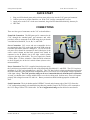
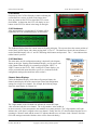
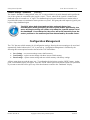
Cheap Control Systems Cheap Twelve Channel (C12C) Servo Controller Version 1.0 The Cheap Twelve Channel (C12C) Servo Controller is a low cost embedded controller that allows a Sony Playstation 2 (PS2) game pad (or equivalent) to control up to twelve standard R/C servos or servo-compatible devices. It provides proportional, momentary, or latched control of all servo channels using the four joysticks and various buttons provided by the PS2 game pad. The C12C also provides dual-channel servo mixing, allowing 6 different pairs of channels to be used with a pair of Electronic Speed Controls (ESC) to provide tank-style skid steering. The C12C supports both tethered and wireless game pads allowing it to be used as a short-range R/C controller (up to 70 feet depending on the wireless game pad used). The C12C is perfect for short-range control of R/C tanks, cars, boats, and robots. OVERVIEW Features ● Supports any PS2 game pad as input device – compact, ergonomic, inexpensive ● Controls up to twelve standard R/C servos or servo-compatible devices ● Joystick channels can be operated in either proportional, momentary or latched modes ● Button channels can be operated in either momentary or latched modes ● Dual-channel mixing mode for all six odd-even pairs of channels ● Servo center, reverse, dead-band and latch speed adjustment on all channels ● All settings can be saved to on-board memory and reloaded automatically on power-up Power ● ● ● Flexible input power +6.0 VDC to +8.4 VDC Provides power to all servos, tethered game pad and wireless game pad receiver Analog light on tethered game pad indicates power on Compatibility ● Works with tethered and wireless game pads that support Analog mode ● Tested with a variety of game pads and servos, including: ○ Servos: Futaba (J connector), Hitec, Airtronics (blue connector) ○ Tethered Game Pads: Sony PSone Analog, Sony Dual-Shock 2 ○ Wireless Game Pads: Pelican, dreamGEAR, MadCatz, Dazzle Revision 2012-08-14 Copyright 2012, Cheap Control Systems 1 of 16 Cheap Control Systems C12C Servo Controller v1.0 QUICK START 1. 2. 3. 4. Plug your PS2 tethered game pad or wireless game pad receiver into the C12C game pad connector Connect your servos, motor controllers, etc. to the C12C just like a standard R/C receiver Apply power to the C12C via the screw terminals, the green LED should flash initially, then stay lit Have fun!! CONNECTIONS There are four types of connectors on the C12C as described here: Game Pad Connection: The PS2 game pad is connected to the C12C through the standard game pad connecter and cable provided, which is connected to the PCB using the 6-pin header via solder holes labeled Bl, Ye, Or, Br, 3v, and GND. Servo Connection: R/C servos and servo-compatible devices are connected to the C12C on the right side of the PCB using the horizontal pin headers labeled 1 through 12. For all servos, the red power wires should be connected to the R (Red) pins in the center vertical column and the black ground wires should be connected to the B (Black) pins in the right vertical column (closest to the edge of the board). The servo signal wire (Futaba = White, Hitec = Yellow, Airtronics = Blue) should be connected to the S (Signal) pins in the left vertical column (closest to the microcontroller). Power Connection: The C12C is supplied electrical power using the 2-position screw terminal on the top side of the board with ports labeled V+ and GND . The C12C requires a minimum of +6 VDC and can handle up to +8.4 VDC. The C12C has a built-in voltage regulator that ensures that the micro-controller, game pad and serial configuration device (see below) receive the proper voltages regardless of the input voltage. The C12C provides voltage to all servo connections directly from the power connection. As such, you should select a voltage suitable for the servo devices being used. In most cases, servos will operate properly with voltages between 6.0v and 8.4v. Battery connections should include appropriate switches and fuses. Serial Connection: The 4-pin header marked “SERIAL” located on the bottom edge of the C12C allows the C12C configuration settings to be modified using either the portable Cheap LCD (CLCD) or a PC connected to the C12C using a USB-to-TTL-Serial cable. See the Configuration Settings section below for more details. Revision 2012-08-14 Copyright 2012, Cheap Control Systems 2 of 16 Cheap Control Systems C12C Servo Controller v1.0 NORMAL OPERATING MODE The factory default settings for the C12C allow it to be used to control up to twelve (12) servos or servocompatible devices without additional configuration. The servo channels are controlled by manipulating joysticks and/or pair of buttons on the PS2 game pad. The PS2 game pad provides 4 joystick controls (left/right and up/down on both joysticks), 4 pairs of buttons on top of the game pad, 2 pairs of trigger buttons on the front of the game pad, a pair of start/select buttons and a pair of “joystick buttons” (activated by pressing down on the joysticks). The game pad inputs are mapped to servo channels as follows: Servo Channel PS2 Input A PS2 Input B 1 Right Joystick – Right Dir Right Joystick – Left Dir 2 Right Joystick – Up Dir Right Joystick – Down Dir 3 Left Joystick – Right Dir Left Joystick – Left Dir 4 Left Joystick – Up Dir Left Joystick – Down Dir 5 Circle Button Square Button 6 Triangle Button X Button 7 Left Pad – Right Button Left Pad – Left Button 8 Left Pad – Up Button Left Pad – Down Button 9 R1 Trigger Button R2 Trigger Button 10 L1 Trigger Button L2 Trigger Button 11 Start Button Select Button 12 Right Joystick – Button Left Joystick - Button Revision 2012-08-14 Copyright 2012, Cheap Control Systems 3 of 16 Cheap Control Systems C12C Servo Controller v1.0 Proportional Joystick Servo Channels The four servo channels controlled by the joystick inputs operate in “proportional” mode. That is, the servo will move one way or the other by an angular distance proportional to the movement of the joystick input. For example, consider a standard servo that moves through an arc of 90 degrees from one extreme to another. With the joystick centered, the servo will move to its center position. When the joystick is moved all the way to the right, the servo will move 45 degrees in one direction. If, however, the joystick is only moved halfway in one direction, then the servo will only move 22.5 degrees in one direction. Since all PS2 game pad joysticks are self-centering, whenever the joysticks are released, the corresponding servos will move back to their center positions. The actual direction moved by the servo arm depends on the type of servo being used. The C12C is designed so that servos compatible with the “Futaba” standard will rotate Clockwise (CW) when a joystick is moved to the “right” or “up”. Servos compatible with the “Airtronics” standard will rotate in the opposite direction. Momentary Button Servo Channels By default, all servos controlled by the PS2 game pad buttons operate in “momentary” mode. Specifically, when the “A” input button is pressed, the servo will move all the way in one direction and when the “B” input button is pressed it will move in the opposite direction. When neither button is pressed, the servo will return to its center position. As with the proportional servo channels, the exact throw and direction of the servo movement depends on the type of servo being used. By default, Futaba-style servos will move Clockwise (CW) when the “A” button is pressed and Counter-Clockwise (CCW) when the “B” button is pressed. Airtronics-style servos will move in the opposite directions. Servo Power Requirements As with most R/C receivers, the supply voltage connected to the C12C is connected directly to the center pin of each servo cable. This allows the servo to draw power directly from the attached battery (or other power source) to ensure maximum performance. The amount of power required depends on the type of servo used and the work being performed by that servo. Although the C12C is capable of controlling up to 12 servos, it is possible for those servos to draw more power than can be supplied by the header pins and PCB traces on the C12C. In most cases, operating a couple servos at a time is not a problem, but any attempt to operate 6 or more servos at the same time could cause power distribution problems. In such cases, power should be connected directly to the servos, bypassing the C12C. That is, only the signal wire from each servo should be connected to the C12C and a separate power connection from the battery to the V+ and GND lines of the servo should be used to supply each servo with power. When supplying power directly to servos from a battery that is different than the one used to power the C12C, you need to establish a “common ground” between the C12C and the servos by connecting a wire between the negative terminal of both batteries. Revision 2012-08-14 Copyright 2012, Cheap Control Systems 4 of 16 Cheap Control Systems C12C Servo Controller v1.0 Configuration Settings The factory default settings allow the C12C to be used to control up to 4 proportional servo devices and 8 momentary servo devices. In addition to the standard operating modes, the C12C supports a number of other servo operating modes, as well as a set of customizable settings to control various features. Configuration settings are changed using the “SERIAL” connector located along the bottom of the C12C connected to either the portable Cheap LCD (CLCD) or a PC using the CCS Serial Cable. In this section, we discuss and show how to configure the C12C using the portable CLCD, but configuration using a PC, the CCS Serial Cable and CCS Serial Terminal software is similar. See the “CCS Serial Configuration Guide” available from: http://www.CheapControlSystems.com/CCS-Serial-Configuration.pdf for complete instructions about installing and using free PC software and resources to configure the C12C using the CCS Serial Cable. Configuration Connection The CLCD is connected to the C12C using the 4-wire patch cable provided with the CLCD. Patch cables may be provided with different color patterns, but you need only remember to connect the same color to the “5V” terminal on both pin connectors. In the photo above, the cable is oriented so that the RED wire is connected to the “5V” pin on both devices. The C12C provides the necessary power to the CLCD, eliminating the need for any separate power connections to the CLCD. The C12C and CLCD automatically configure their serial interfaces on power-up. Therefore, you should always connect the serial cable to both devices before powering up the C12C. Connecting or disconnecting the serial device while the C12C is running could prevent the CLCD from properly synchronizing with the C12C. In such cases, power cycling the C12C should fix the problem. If you don't see anything when the CLCD is powered up you may need to adjust the display contrast by turning the potentiometer located on the right side of the board, just below the LCD. Revision 2012-08-14 Copyright 2012, Cheap Control Systems 5 of 16 Cheap Control Systems C12C Servo Controller v1.0 C12C Banner On power-up, the CLCD will display a banner indicating the current firmware version, as shown in the image above. Press any button on the CLCD to signal the C12C to start Serial Mode. At that point, the C12C will display its own banner on the CLCD, as shown in the image on the right. C12C Dashboard After approximately 1/2 second, the C12C banner will be replaced by the C12C dashboard display, as shown here: The dashboard display shows the current status of all game pad inputs. The top row shows the current position of each of the 4 joystick inputs, with values ranging from -127 to 127. The bottom row shows the current status of each of the button inputs, with “A” and “B” indicating which buttons are depressed. The “-” value indicates that neither button is pressed. C12C Main Menu The main menu used for configuration settings is depicted by the diagram shown on the right. Starting at the Dashboard display, you can access each of the Channel Status Displays by repeatedly pressing the “NEXT” or “PREV” buttons on the CLCD. After viewing all 12 status displays, you will be presented with menus that allow you to save, load and reset the configuration settings (discussed later in this section). Channel Status Displays Unlike the dashboard display, which shows all game pad inputs, the channel status display shows the current input values and configuration settings for a single servo channel. For example, the following image shows the status display for Channel 01: The 3-digit number on the left-hand side indicates the current PS2 input value associated with this servo channel. The 4-digit number in the middle shows the current servo pulse width in micro-seconds (1.5ms corresponds to the standard servo center position). The 3-digit number to the right indicates the “scale factor” assigned to the servo channel. Finally, the first “N” shown indicates that the servo is operating in “Normal” mode and the second “N” indicates that the servo will move in the “Normal” direction. (All of the settings associated with these values will be discussed shortly.) Revision 2012-08-14 Copyright 2012, Cheap Control Systems 6 of 16 Cheap Control Systems C12C Servo Controller v1.0 Channel Settings Menu The Channel Settings Menu for a given channel is accessed by pressing the “INCR” button when the Channel Status Display is shown. Thereafter, the “NEXT” and “PREV” buttons can be used to navigate through each of the channel settings, as depicted in the diagram shown on the right. For each channel setting, the top row in the Channel Display Status will be replaced by text indicating the setting name and the current value. For example, the following display: shows the current “Enabled” setting is “ON” for Channel 01 (as indicated by the “01” on the left side of the top row). The current status for the selected channel is always shown on the second line, allowing you to immediately test any changes made to the settings. This allows you to quickly try different settings until you've configured the channel as desired. In all cases, individual settings are changed by pressing the “INCR” and “DECR” buttons, which either cycles through the available choices for that setting or increments/decrements the numeric value associated with that setting. We now discuss the purpose of each setting and the values supported. Channel Settings – Enabled (ON, OFF) The channel “Enabled” setting (default value “ON”) indicates when a servo signal should be generated on the selected channel. Channel Settings – Reverse (ON, OFF) The channel “Reverse” setting (default value “OFF”) indicates when the servo direction should be reversed. When “Reverse” is “OFF”, a Futaba-compatible servo will move Clockwise (CW) when a joystick is moved in the “A” direction or an “A” channel button is pressed. When “Reverse” is “ON”, a Futaba-compatible servo will move Counter-Clockwise (CCW) when a joystick is moved in the “A” direction or an “A” channel button is pressed. NOTE: Airtronics-compatible servos move in the opposite direction of Futaba-compatible servos. Channel Settings – Center (-250 to +250) The channel “Center” setting (default value “0”) specifies the center offset (in micro-seconds) for the servo relative to the standard 1.5ms center pulse width. For a standard 90 degree servo, a center offset value of -250 or +250 is approximately 45 degrees or half of the servo arc. Revision 2012-08-14 Copyright 2012, Cheap Control Systems 7 of 16 Cheap Control Systems C12C Servo Controller v1.0 Channel Settings – Scaling (0 to 150) The channel “Scaling” setting (default value “100”) specifies a scale percentage to be applied to the servo pulse width output by the C12C. A value of 100 percent indicates that the standard pulse width should be generated, which results in a 90 degree sweep for standard servos. A value of 150 percent extends the pulse width by 50% which results in a 180 degree sweep for most standard servos, while a value of 50 percent results in a 45 degree sweep. NOTE: The exact sweep arc exhibited by a given servo for a given scale factor depends on the specific servo model and center offset. Some servos support wider arc ranges than others. Channel Settings – Mode (NORMAL, UNI-HALF, UNI-FULL, LATCHED) The channel “Mode” setting (default value “Normal”) specifies how the servo signal is generated relative to the PS2 input. In all modes, the “Reverse”, “Center” and “Scaling” settings work as expected. In “Normal” mode, the servo moves in a “momentary” fashion, moving to an off-center position only when the PS2 input is active. For example, when a joystick is moved one way or the other, the servo will move accordingly. Similarly, when a button is pressed, the servo will move to the extreme position in the corresponding direction. In all cases, when the input is no longer activated, the servo will move back to its center position. In “Uni-Half” mode, the servo moves only in one direction (through a 45-degree half-arc), regardless of which input is activated. For joystick channels, the servo will always move in the “A” direction proportionally, independent of the direction that the joystick is thrown. For button channels, the servo will always move in the “A” direction, regardless of which button is pressed. In all cases, when the input is no longer activated, the servo will move back to its center position. In “Uni-Full” mode, the servo moves from one extreme to another (through a 90-degree full-arc), regardless of which input is activated. For joystick channels, the servo will move in the “A” direction proportionally from one extreme to another, independent of the direction that the joystick is thrown. For button channels, the servo will always move in the “A” direction from one extreme to another, regardless of which button is pressed. In all cases, when the input is no longer activated, the servo will move back to the extreme position in the “B” direction. In “Latched” mode, the servo moves in the direction indicated by the joystick or button pressed. The servo moves at a pre-defined rate (see “Latch Step” setting below) until the joystick or button is released or the servo reaches the extreme position in a given direction. The servo will remain in place until the input is activated again, causing it to move in the same or opposite direction. Channel Settings – Latch Step (1 to 8) The channel “Latch Step” setting (default value “8”) indicates how fast the servo should move when operating in “Latched” mode. A step value of “1” results in the slowest motion, while a value of “8” results in the fastest motion. Channel Settings – Pri Input (00 to 12) The channel “Pri Input” setting (default value “00”) specifies the primary input channel used to control the selected servo channel. The default value of “00” indicates that the standard input for that channel should be used (e.g., servo 01 = input 01, servo 02 = input 02, etc). This feature allows multiple servo channels to be controlled by the same input channel. For example, if the “Pri Input” settings for servo channels 11 and 12 are both set to “01”, then all three servos (01, 11, and 12) will move in unison when the right joystick is moved left or right. When combined with individual “Reverse”, “Center”, “Scaling” and “Mode” settings, a wide range of coordinated servo activity can be controlled by a single input channel. Revision 2012-08-14 Copyright 2012, Cheap Control Systems 8 of 16 Cheap Control Systems C12C Servo Controller v1.0 Channel Settings – Sec Input (00 to 12) The channel “Sec Input” setting (default value “00”) specifies an optional secondary input channel used to control the selected servo channel. The secondary input allows two different input channels to be used to control the same servo. For example, suppose that “Sec Input” is set to input channel “05” for servo channel “01”. In that case, servo “01” will move whenever the right joystick is moved left/right (input channel “01”) or whenever the “Circle” or “Square” buttons are pressed (input channel “05”). That is, activating either input channel “01” or input channel “05” will cause servo “01” to move. Another common use of the secondary input channel would be to bind together all four “trigger” buttons to control a single external device (such as a paintball marker trigger). In this example, assume that the device is triggered when servo channel “09” moves in the “A” direction. To activate the device whenever any of the four trigger buttons are pressed, we set “Sec Input” to “10” and set “Mode” to “Uni-Half” for servo channel “09”. Channel Settings – Mixing (ON, OFF) The channel “Mixing” setting (default value “OFF”) determines when a pair of input channels should be mixed to provide tank-style control. When “Mixing” is “ON” for a given channel, the input value from that channel will be mixed with the input channel from the “adjacent” channel to generate two new input values. Mixing can be designated for channel pairs 1-2, 3-4, 5-6, 7-8, 9-10 and 11-12, but mixing is most commonly specified for the right and left joystick channel pairs, 1-2 and 3-4. When two input channels are mixed, the lower numbered input channel represents the “steering” channel and the higher numbered input channel represents the “throttle” channel. On the output side, the lower numbered servo channel represents the “left” motor and the higher numbered servo channel represents the “right” motor. In common usage, when used in conjunction with a pair of bi-directional motor controllers, up (down) movement of the joystick will cause the vehicle to go forward (reverse) at a speed proportional to the throw of the joystick. Similarly, left (right) movement of the joystick will cause the vehicle to spin left (right) at a speed proportional to the throw of the joystick. The C12C uses a “full precision” mixing algorithm that results in the smoothest possible speed transitions across all input values, as depicted in the following mapping diagrams: As the joystick moves straight up or down from the center, motor speeds increase smoothly towards their maximum values. As the joystick moves right or left, motor speeds are smoothly adjusted to cause the vehicle to turn more or less gradually. Revision 2012-08-14 Copyright 2012, Cheap Control Systems 9 of 16 Cheap Control Systems C12C Servo Controller v1.0 Channel Settings – Deadband (0 to 127) The channel “Deadband” setting (default value “24”) is only available for joystick channels and it specifies the size of the region to be considered as the joystick “center”. That is, whenever the joystick is located in the deadband region it is treated as a “0” input. The deadband region prevents inadvertent servo motion when a joystick doesn't return to its mechanical center position every time. PS2 game pads with imprecise joystick pots require a larger deadband region. The C12C takes both the deadband size and scale factor into consideration when generating the servo pulse width. Specifically, the servo will begin moving off-center only when the joystick moves out of the deadband. From that point, the servo will move smoothly from the center position to the extreme position determined by the scale factor. Configuration Management The C12C has non-volatile memory for all configuration settings, allowing the current settings to be saved and automatically loaded whenever the C12C is powered up. Configuration management is facilitated by the following three menu options located at the end of the C12C Main Menu: Save Settings – save current settings to non-volatile memory Load Settings – replace current settings with those in non-volatile memory Reset Settings – replace current settings and non-volatile memory with factory settings All three menu items are used the same way. To perform the desired action, press the “INCR” button. At that point, a confirmation display will appear. Press the “INCR” button again to confirm the action to be performed. If you want to cancel the action, press any of the other buttons to return to the “Dashboard” display. Revision 2012-08-14 Copyright 2012, Cheap Control Systems 10 of 16 Cheap Control Systems C12C Servo Controller v1.0 Testing / Tutorial The following procedures are provided as a good way to learn and/or test most C12C features. You'll need the following items in order to conduct the tests: Fully assembled C12C Cheap LCD (CLCD) or PC with CCS Serial Cable and CCS Serial Terminal software Battery – 6v to 8.4v Battery switch Tethered or wireless PS2 game pad At least two standard R/C servos Battery Connection The battery must be connected to the C12C as follows: the POSITIVE (RED) battery wire must be connected to the V+ terminal on the C12C the NEGATIVE (BLACK) battery wire must be connected to the GND terminal on the C12C Whenever possible, you should use a switch between the battery and the C12C to turn the power on/off instead of disconnecting the battery wires from the screw terminals. This reduces the likelihood of connecting the battery wires improperly. Failure to connect the battery wires properly could result in permanent damage to the C12C, CLCD, game pad and/or servos. You've been warned. Test 1 – Game Pad Communication 1. Connect a tethered or wireless PS2 game pad to the C12C, but do not connect any servos. Power on the C12C. The GREEN led on the C12C should flash a few times, then stay lit. The Analog led on the game pad should be lit, indicating that the C12C is properly communicating with the game pad. 2. If the GREEN led does not flash initially, then check the battery connection and ensure that the battery is providing at least 6 volts to the C12C battery terminal. If the problem persists, then either the microcontroller has been damaged or there is an electrical problem with the C12C board. 3. If the GREEN led flashes continually, then the C12C cannot communicate properly with the game pad and you should check the game pad connection. If you are using a wireless game pad, then you should verify that the PS2 game pad is properly “synced” with the wireless receiver. Follow the instructions provided with your wireless game pad to perform the proper synchronization procedure. 4. Disconnect the PS2 game pad (or receiver) from the C12C. The GREEN led on the C12C should flash. 5. Re-connect the PS2 game pad (or receiver) to the C12C. The GREEN led on the C12C should stay lit and the Analog led on the game pad should be lit. 6. Power off the C12C Revision 2012-08-14 Copyright 2012, Cheap Control Systems 11 of 16 Cheap Control Systems C12C Servo Controller v1.0 Test 2 – Servo Channels 1. Connect a single servo to Channel 01 and power on the C12C. The servo may immediately move to the center position when it is powered on, depending on where it was last positioned. 2. Move the right joystick left and right to move the servo one way and the other. A standard servo should move proportionally up to 45 degrees in each direction from the center position for an overall 90 degree sweep. Depending on the quality of the game pad, the joystick may not always mechanically return to the center position. If so, jiggle (yes, that's the technical term) the joystick until it does. 3. Move the servo to another joystick channel and repeat steps 1-2 until all joystick channels have been tested. 4. Move the servo to Channel 05. Press the Circle and Square buttons to move the servo one way and the other. A standard servo should move to an extreme 45 degree position when either of the buttons is pressed. 5. Repeat step 4 for servo channels 06 through 12. 6. Connect two or more servos to various channels and manipulate the game pad inputs to control the servos at the same time. 7. Power off the C12C The following tests refer to a “Serial Device” used to configure the C12C, which can either be a Cheap LCD (CLCD) or a PC with a Cheap Serial Cable and Cheap Serial Terminal software. Test 3 – Serial Communication 1. Connect the 4-wire serial cable from the Serial Device to the SERIAL port on the C12C. Ensure that the same colored wire is connected to the “5V” pin on the C12C pin header and to the “5V” pin on the Serial Device. 2. Power on the C12C. a) If a CLCD is being used as the Serial Device, it should power up and should display the CLCD banner. If nothing is displayed on the CLCD, perform the following tests: • Check the serial cable to ensure that it is connected properly • Turn the potentiometer on the CLCD to adjust the screen contrast • Power cycle the C12C to ensure the serial lines are synchronized b) If a CCS Serial Cable is being used as the Serial Device, connect the USB plug to the PC, wait for Windows to signal that the device has been found and then start the CCS Serial Terminal software. At that point, a blank screen will be displayed. 3. Press any button on the Serial Device to signal the C12C to start Serial Mode. At that point, the C12C banner should be displayed on the Serial Device for approximately ½ second. After that, the C12C Dashboard display should appear. Revision 2012-08-14 Copyright 2012, Cheap Control Systems 12 of 16 Cheap Control Systems C12C Servo Controller v1.0 4. Move the joysticks on the C12C. The Dashboard display should show the joystick input values as the joysticks are moved. 5. Press one or more buttons on the C12C. The Dashboard display should show “A” or “B” input values depending on which buttons are pressed. 6. If using a CCS Serial Cable, close the CCS Serial Terminal application and disconnect the USB plug from the PC 7. Power off the C12C Test 4 – Servo Settings 1. Connect one servo to Channel 01 and another servo to Channel 02 2. Connect the Serial Device to the C12C Serial Port. 3. Power on the C12C. If using a CCS Serial Cable, connect the USB plug to the PC and start the CCS Serial Terminal application. 4. Press any button on the Serial Device to signal the C12C to start Serial Mode. At that point, the C12C banner should be displayed on the Serial Device for approximately ½ second. After that, the C12C Dashboard display should appear. 5. Press the “NEXT” button on the Serial Device to display the Channel 01 Status display. Move the right joystick “LEFT” and “RIGHT”. The servo connected to channel 01 should move back and forth. The Channel 01 Status display should show the current joystick input value and the current servo pulse width. 6. Press the “NEXT” button on the Serial Device to display the Channel 02 Status display. Move the right joystick “UP” and “DOWN”. The servo connected to channel 02 should move back and forth. The Channel 02 Status display should show the current joystick input value and the current servo pulse width. 7. Press the “PREV” button on the Serial Device to return to the Channel 01 Status display. 8. Press the “INCR” button to enter the Channel 01 Settings menu. The “Enabled” settings should be displayed on the top display line. 9. Press the “INCR” button to disable servo channel 01. Move the right joystick left and right. The servo connected to channel 01 should not move. Press the “DECR” button to re-enable the servo channel. Confirm by moving the joystick left and right. 10. Press the “NEXT” button to display the “Reverse” setting. Press “INCR” or “DECR” to toggle the reverse setting. Confirm proper operation by moving the joystick and noting the direction of the servo. 11. Press the “NEXT” button to display the “Center” setting. Press “INCR” or “DECR” to adjust the center position. The servo should move ever so slightly as the center offset is adjusted. You can press and hold either button to auto-increment or auto-decrement the value. 12. Press the “NEXT” button to display the “Scaling” setting. Press “INCR” or “DECR” to adjust the scale factor. Move the joystick to confirm that the full range of the servo depends on the scale factor. Revision 2012-08-14 Copyright 2012, Cheap Control Systems 13 of 16 Cheap Control Systems C12C Servo Controller v1.0 Test 5 – Servo Modes This test begins at the point where Test 4 ended 1. Press the “NEXT” button to display the “Mode” setting, then press the “INCR” button to select the “UNIHALF” mode. Confirm that an “H” is displayed on the right-side of the status line. Move the joystick left and right. Confirm that the servo only moves in one direction. (Note, the actual direction depends on the type of servo used and the current “Reverse” setting.) 2. Press the “INCR” button to select the “UNI-FULL” mode. Confirm that an “F” is displayed on the rightside of the status line. Move the joystick left and right. Confirm that the servo only moves in one direction, from one servo extreme to the other. 3. Press the “INCR” button to select the “LATCHED” mode. Confirm that an “L” is displayed on the rightside of the status line. Move the joystick left and right. Confirm that the servo only moves when the joystick is not centered and that the servo stays in its last position when the joystick is centered. 4. Press the “NEXT” button to display the “Latch Step” setting. Use the “INCR” and “DECR” buttons to adjust the latch step. Confirm that the servo moves faster or slower depending on the latch step size. 5. Press the “PREV” button to return to the “Mode” setting. Press the “INCR” button to return to the “Normal” servo mode. Test 6 – Servo Mapping This test begins at the point where Test 5 ended 1. Press the “NEXT” button to display the “Pri Input” setting, then press the “INCR” button TWICE to set channel “02” as the primary input channel. Move the right joystick LEFT and RIGHT. No servos should move. Move the right joystick UP and DOWN. Both servos should move in unison. Press the “DECR” button TWICE to set channel “00” as the input channel. 2. Press the “NEXT” button to display the “Sec Input” setting, then press the “INCR” button 5 times to set channel “05” as the secondary input channel. Move the right joystick LEFT and RIGHT. Servo 01 should move proportionally with the joystick. Press the CIRCLE and SQUARE buttons on the game pad. Servo 01 should move to the extreme 45 degree positions when the buttons are pressed. 3. Press the “NEXT” button to display the “Mixing” setting, then press the “INCR” button to toggle mixing “ON”. a) Move the joystick UP. Both servos should move in the same direction (assuming they are the same model and the “Reverse” setting is the same for both channels). b) Move the joystick DOWN. Both servos should move in the other direction. c) Move the joystick LEFT. Both servos should move in opposite directions. d) Move the joystick RIGHT. Both servos should move in the other, opposite directions. e) Move the joystick to various points on the circle and confirm that the servos move proportionally based on the throw of the joystick in the X and Y directions. Revision 2012-08-14 Copyright 2012, Cheap Control Systems 14 of 16 Cheap Control Systems C12C Servo Controller v1.0 Test 7 – Configuration Management This test begins at the point where Test 6 ended. 1. Press the “NEXT” button until the “Save Settings?” menu item appears 2. Press the “INCR” button to save the settings, then press “DECR” to cancel the action, returning to the Dashboard display. 3. Press the “NEXT” button until the “Save Settings?” menu item appears 4. Press the “INCR” button to save the settings, then press “INCR” to confirm the action. A message should be displayed indicating that the settings have been saved. Press any button to display the Dashboard. 5. Power cycle the C12C. 6. Move the right joystick and confirm that channel mixing is still working. 7. Set the “Mixing” setting to “OFF” for Channel 01. Move the joystick to confirm that mixing is off. 8. Press the “NEXT” button until the “Load Settings?” menu item appears 9. Press the “INCR” button to load the settings, then press “INCR” to confirm. A message should be displayed indicating that the settings have been loaded. Press any button to display the Dashboard. Move the joystick to confirm that channel mixing is “ON”. 10. Press the “NEXT” button until the “Reset Settings?” menu item appears 11. Press the “INCR” button to reset the settings, then press “INCR” to confirm. A message should be displayed indicating that the settings have been reset. Press any button to display the Dashboard. Move the joystick to confirm that channel mixing is “OFF”. 12. Power off the C12C. Revision 2012-08-14 Copyright 2012, Cheap Control Systems 15 of 16 Cheap Control Systems C12C Servo Controller v1.0 NO WARRANTIES Do not use this product in a health care or personal safety application. This product is provided without any express or implied warranty. Cheap Control Systems cannot be held responsible if your C12C does not work for any reason. Cheap Control Systems cannot be held responsible if your C12C damages any other devices. Cheap Control Systems cannot be held responsible for electrical or electromagnetic interference resulting from use of your C12C. Cheap Control Systems cannot be held responsible for any personal injury, property damage or loss of profit resulting from use of your C12C. Cheap Control Systems does not warrant the accuracy or completeness of any documentation. Cheap Control Systems may change documentation or the products described therein, at any time without notice. Cheap Control Systems makes no commitment to update documentation. Revision 2012-08-14 Copyright 2012, Cheap Control Systems 16 of 16