1
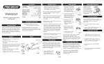
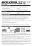
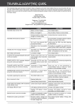
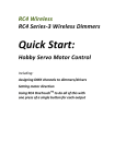
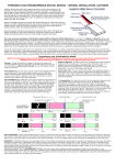
Telebee Heading Lock
Piezo Gyro
Instruction Manual
Warning, if any radio system is used other than those listed make
sure same polarity is maintained and double check your connections, otherwise you will
Rudder Servo
damage the Aerotech
(Fast Speed)
gyro.
Reverse
Switch
Rudder Servo In
Rudder Channel
on Rx
Gain
Red Lead
CN2238
For Helicopter Use
Mfg. test
port (not
for end
user)
Please read instructions
completely before operation.
Features:
Heading lock & rate mode selectable - Remote & manual gain settings Solid state with no moving parts for nearly unlimited use - Small and
lightweight sensor with amplifier module - Temperature differential
compensated circuitry - Offset drift cancellation during initialization phase Compatible with JR, Futaba, Hitec and Airtronics “Z” radio systems.
Specifications:
Dimensions: 1.28”L x 1.28”W (1.50” at Base) x 1.10“H - Weight: 24.5 g
(0.69 oz) sensor & 15.5 g (0.44 oz) amp - Power Supply: 4.8 -7.2 Volts Current Consumption: 33 ma - Operating Temp: 23° - 130°F.
High Speed Servo Selection:
A quality high speed ball bearing servo is required for use with
the Heading Lock mode. Due to the extremely fast response in
the Heading Lock mode, regular servos will overheat and eventually fail. The actual torque of the servo is not as important as the
speed which should fall between 0.16 ~ 0.06 seconds per 60
degrees rotation.
Helicopter Tail Rotor System:
The maximum holding power (the actual gain setting that will
dampen the largest input without the tail oscillating) is directly
related to how rigidly the tail assembly is attached to the helicopter. Loose tail support struts, tail boom fixture bolts or slipping tail
drive shaft/belt will all contribute to reducing the holding power on
the tail. A smooth rudder tail linkage is the key factor to check
and maintain to keep a reliable, strong tail for the helicopter.
Supplied Connectors:
Two harnesses are provide to connect the amplifier to the
receiver, these are a direct fit for Futaba.
White
= Signal
Red
= Pos +
Black
Red
White
Black
= Neg -
Top
Solid top surface of
connector to be
bevelled.
To
p
JR and Airtronics “z” require the (rx) plugs to have the top corners
bevelled as shown. Using a small flat file or careful scraping with
a knife remove enough material to easily insert into the receiver.
Radio Connector Type
JR
red to red
black to brown
white to orange
Futaba
red to red
black to black
white to white
Hitec
red to red
black to black
white to yellow
Airtronics Z
red to red
black to black
white to blue
Gear/Aux Channel
(Switch) on Rx
Receiver
Connect to
Gyro
If the red light flashes on the gyro, no signal is being received, turn off.
Turn on the transmitter and turn the gyro back on. Also, if the gyro
needs to be reversed, switch off the gyro, move the reverse switch and
turn the gyro back on.
Transmitter Settings:
Servo Reverse
Travel* (ATV or
EPA)
Revo Mix
H
L
Up
Down
Sub Trim / Mechanical Trim
Rudd
N
100%
100%
0%
0%
0
Gear/Aux
N
100%
100%
0
*Settings based on a JR 6 channel radio, note the initial Rudder (ATV or
EPA) is set at 100%, the control ball location (distance from servo center
to the hole on the servo horn) needs to be set such that as the pitch plate
travels through the entire movement range no mechanical linkage binding
occurs. If necessary move the control ball one hole inwards on the horn.
Mounting the gyro sensor:
1. Each helicopter kit recommends a location for mounting the
gyro sensor, usually close to the main shaft. Keep away from the
engine and exhaust system due to changes in temperature
affecting the gyro. Mount the amplifier in the servo tray along with
the receiver and battery pack. The surface that the sensor will be
mounted need to be prepared with a mild cleaner that will not
degrade the surface that the foam tape with adhere to (rubbing
alcohol is recommended.) Using two pieces of foam tape, double
up and attach to the bottom of the sensor base. Then attach the
sensor with the adjustable pots facing an open direction for
access. Make sure the sensor does not contact the helicopter
frame or other radio components or wiring.
Step 1 Turning the Gyro On for the First Time:
Disconnect the rudder pushrod from the servo horn. After
connecting the rudder servo to the gyro and both the Rudder lead
and the Aux/Gear lead to the receiver, switch the gyro on and wait
10 seconds for the gyro to initialize (the rudder servo with twitch
to indicate it is ready). The moment the servo twitches watch the
rudder servo, the servo will stay in one position (rate mode) or will
start moving in one direction (heading lock mode). If in heading
lock mode, toggle the Gear switch to rate mode for now. It is
completely normal for the servo to move all the way to one side
and stop while in heading lock mode, it is extremely important that
the rudder pushrod is not connected. The servo will stop based
on the Rudder ATV/EPA setting, currently at 100%. Turn off the
gyro for now. Once more review your radio and ensure that
Revolution Mixing (revo) is inhibited or the Up and Down settings
are set to zero. Reset your sub trims, trim tabs to neutral and
make sure the rudder servo does not move (without gyro connected) when switching flight modes.
Step 2 Setting the Heading Lock Neutral:
Toggle the Gear / Aux switch into heading lock mode, using the
electronic sub trim for the rudder channel, add left or right trim to
minimize the servo from moving. This may require you to switch
back to rate mode once to reset the servo. Remove the servo
horn and reset the horn to 900 or the helicopter’s neutral position
for the rudder servo. Now the rudder trim is only used in the
heading lock mode to keep the servo in neutral. Occasionally
the neutral needs to be reset with
changes in temperature.
90°
pushrod
Always wait 10-15 minutes
before flying for the helicopter
at the beginning of the day to
stabilize with the outside
12-16mm
temperature.
Step 3 Rudder Servo Setup:
1. Disconnect the tail pushrod from the rudder servo and check
that the pushrod is smooth and requires only a gentle force to
move from one endpoint to another through the entire range of
movement. Make necessary changes if needed.
2. Following the instructions provided with the helicopter set the
rudder pushrod length so the pitch slider is centered within it’s
movement range and has the proper 5° of tail pitch to hold the
helicopter straight in a hover.
3. Turn on the gyro and wait the 10 seconds while it initializes.
Switch to rate mode so the servo returns to center. Move the
rudder stick completely to the left side and select the hole on the
servo horn for the control ball or “z” bend that allows complete
travel without binding. Now move to the right side to check for
binding. Only adjust the position of the control ball to achieve
complete throw (generally between 12-16mm from the center of
the servo), leave the Rudder ATV/EPA at 100% on both sides, this
permits perfect mechanical setup.
Do not change the rudder trim tabs as these are assigned to the
Heading Lock mode. Continue until tail holds straight in a hover.
Nose turns left
increase* tail pitch by shortening pushrod
Nose turns right
decrease* tail pitch by lengthening pushrod
*Settings are based on helicopters with the tail rotor assembly mounted on
the right hand side of the helicopter when viewed from behind.
Finishing Setup:
At this stage the helicopter will be setup for both heading lock and
rate mode flying. Remember, if any changes are made to the
heading lock trim or the reverse switch on the gyro, switch the
gyro off and let the gyro re-initialize when turned back on.
Troubleshooting Gyro Gain:
1. If hunting occurs at less than 65% while hovering then:
a) check for excessive free play in the rudder pushrod
b) increase the foam tape thickness below the gyro
c) shorten the tail rotor blades
2. If no hunting occurs at 100% while hovering then:
a) lengthen the tail rotor blades.
Basic Transmitter Configuration:
The following chart lists
how the gyro mode
settings corresponding
to the switch position on
the radio.
To change the Heading
Lock / Rate position on
the assigned switch
change the direction of
the Servo Reverse
switch for the Gear /
Aux channel.
JR / Airtronics Z
Heading Lock
Rate
Gyro Direction
Switch
Front
Back
N
Futaba / Hitec
Heading Lock
Rate
Gyro Direction
Switch
Back
Front
R
Step 4 Gear Channel ATV (Gain Settings):
The Gear ATV (travel
volume) controls the
both gain settings for
the gyro. Initially set
both values to 50% as
a starting point.
Rudder Channel ATV (Pirouette Rate & Servo Limits):
Gear ATV / EPA
Up
Down
100% 100%
75%
75%
50%
50%
Gain Setting
100
75
start at 50
Step 5 First Flight Heading Lock Mode:
Start with the switch in Heading Lock mode. As the throttle stick
is increased the rudder servo will slowly move the pitch plate to
one side, while the helicopter is still on the ground glance at the
tail pitch plate and add a small rudder input to re-center the pitch
plate before lift off. Bring the helicopter to a hover and keep
increasing the Heading Lock Gain (Gear ATV) until the tail starts
to oscillate (hunt). At this point reduce Gain setting slightly (510%). Bring the helicopter into slow forward flight. If hunting
occurs, reduce the gain setting slightly. Continue until fast
forward flight is possible without the tail hunting, record this value.
If hunting suddenly occurs later, thoroughly check the helicopter
for worn parts in the tail pushrod system.
Step 6 First Flight Rate Mode:
Start with the switch in Rate mode and an initial gain setting of
50% on the Gear channel (ATV). Beginners should be using
training gear at this step. Slowly increase throttle stick until the
helicopter is still on the ground, just prior to lift off. Increase the
throttle slightly and observe the direction the helicopter starts to
rotate and reduce the throttle to an idle. All adjustments from
here are made to the length of the rudder pushrod only.
Rudder ATV / EPA
Left
Right
Servo Throw
Pirouette Speed
0
0
100% 100%
+40 / -40
Fastest
75%
75%
+350 / -350
Medium
50%
50%
+300 / -300
Slow
The Rudder ATV (travel volume) controls the servo endpoints
which ultimately controls the maximum pirouette speed that the
helicopter will achieve. After flight testing, these values can be
modified to get the desired control response from the tail.
Warranty Coverage
Your new equipment is warranted to the original purchaser against
manufacturer defects in material and workmanship for 90 days from the
date of purchase. The warranty is limited to the original purchaser and is
not transferable. This warranty does not apply to any unit which has been
improperly installed, mishandled, abused or damaged in a crash, or to
any unit which has been opened, repaired or altered by any unauthorized
agencies. Under no circumstances will the buyer be entitled to consequential or incidental damages. Do not subject your gyro to extreme
temperatures, humidity or moisture or in direct sunlight for long periods of
time. Due to the delicate nature of the electronic components, the impact
of dropping the gyro to the floor can damage the unit.
If the gyro requires service and is within the warranty period, call for
a return authorization # and include a copy of the original receipt. Return
your gyro unit only in the original box with foam packaging. Package the
unit in a sturdy container and include full return address and description of
damage. Send the parcel insured and postage prepaid, please allow 8-12
weeks for service.
Non-warranty repairs- You will be advised on the repair cost, please
allow 8-12 weeks for service.
Century Helicopter Products: 523 Sinclair Frontage Road, Milpitas, CA 95035 USA