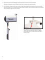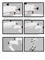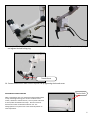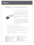
1
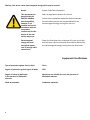
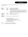
ENT Microscope LED
User’s Manual
Table of Contents
Installation and Assembly
LED Illumination System Instructions
Description
Set Up
Maintenance
Specifications
Environmental Limitations
LED Warranty
Interpupillary Adjustment
Parfocalizing
Magnification Table
Color Filter
Cleaning Instructions
Dimensions
Microscope Parts Breakdown
Microscope Details
Owner’s Record
1
6
9
10
11
12
12
13
14
14
14
15
15
16
17
18
19
Installation and Assembly
1. Remove the base from the box and set base
bottom up (casters facing up) on the cardboard
or foam from the box for cushion.
2. Remove the base weights from the weights
box and insert the weights one at a time into
the bottom of the base.
Align the pins with the holes and depress the
thumb lock button to put the weights into
place.
Flip the base over so that the top center post
is facing upward.
* Be sure to check to make sure that the
weights are secured before flipping the
base over.
1
3. Remove the pole from the packaging and insert pole into the center post hole in the base.
Align the two indention marks in the pole to the holes in the base center post hole collar.
4. Once the pole is secured into the base, insert the Light Housing/Light Source portion of the microscope into
the top of the pole. This is where the illumination system is housed. Make sure that the light source is secured
while inserting the light source into the pole.
Once the pole is in the collar and indentions are
aligned, use the provided Allen Wrench to tighten
the two Allen bolts in the base center post collar to
secure the pole.
2
5. Next insert the Pantographic Arm into the light source.
6. Loosen the two set screws on the bottom arm cover
with Allen Wrench provided.
7. Remove the bottom cover.
8. Place the LED cable through the bottom cover.
9. Secure the bottom cover by tightening the set screws with the Allen Wrench.
3
Plunger
10.After the Pantographic Arm is inserted and the LED cable is secure, add the extension piece into the top of the Pantographic Arm on the under side. Be sure to loosen the black knob and pull plunger on the Pantographic
Arm in order to insert the extension arm. Screw on the white locking knob.
11.Next, insert the 45 degree coupler into the extension arm. Screw down the white locking knob.
12.Insert the Angle Arm into the 45 degree coupler. Screw down the white knob.
4
13.Insert the LED cable into the electrical connector on the Optical Pod. Be sure to the plug is seated completely
and tighten Knurled locking ring.
Thumb Screw
14. Secure the Binocular Head onto the Optical Pod by tightening the thumb screw.
PANTOGRAPHIC ARM BALANCING
Tension Knob
NOTE: Pantographic Arm may need tension adjusted (black knob
on top nearest light housing, turn counter-clockwise to add
tension, clockwise to release tension). This may need to be done
if camera/video are added to the scope. This will increase or
decrease the tension to desired function for user. The
Pantographic Arm may have to be in the horizontal position to
make adjustments.
5
LED Illumination Instructions
Symbols
Symbols Used in this Manual or on the Device
NOTE: This term contains importantinformation regarding set-up and operation to facilitate ease of use and obtain effective results.
This term contains critical information regarding safe handling and use of this system. Device
malfunction or property damage could result if these instructions are not followed.
This symbol cautions that surfaces may be hot and could be a burn hazard.
WARNING:
This term contains critical information by identifying conditions or practices that may result in injury or loss of life if these instructions are not followed.
Hazard
Actions To Be Taken/Prevented
General
Read the manual in its entirety and heed all safety warnings before operating the light source.
Only qualified personnel shall inspect the unit for internal damage.
Warning - This device emits high intensity light that can be harmful.
WARNING
HIGH INTENSITY
Hazard
Actions To Be Taken/Prevented
LIGHT
Do not look
Exposure
to
directly at light
intense bright
light
Never look directly into the objective lens of the microscope when the unit is
turned on as the light intensity can be damaging.
Warning - This device presents a risk of fire.
Hazard
Actions To Be Taken/Prevented
Fire
Do not operate the unit near any flammable materials including flammable gases or liquids.
If the microscope is to be cleaned with a volatile liquid (such as IPA) turn off the unit before proceeding.
After cleaning allow vapors to disperse before turning on.
6
Warning -This device presents a burn risk.
WARNING
Hazard
Burn hazard.
Hot surface inside.
Allow to cool
The
unit
before servicing.
produces
significant
amounts of
heat.
Actions To Be Taken/Prevented
Always allow the unit to cool to ambient temperature before attempting
any adjustments or replacement of parts.
Warning -This device can overheat.
WARNING
Hazard
Burn hazard.
Actions To Be Taken/Prevented
Hot surface inside.
Allow to cool
Microscope
Do not block air inlets or outlets (vents) with anything including
before servicing.
overheating plastic protection covers.
If the microscope overheats it will turn the light off. If this happens, turn off `
the unit and allow sufficient time for the unit to cool (approx. 10 minutes) then turn the unit back on.
If the light still remains off, turn off the unit and allow more time for cooling.
Vent
Vent
Warning - This device presents a risk of electrical shock.
Hazard
WARNING
WARNING
HAZARDOUS
VOLTAGE
Only authorized
personnel may
This
device
Disconnet power
service this
before servicing.
operates
at
equipment
Actions To Be Taken/Prevented
Only qualified personnel shall inspect the unit for internal damage.
high electricalOnly operate the equipment in a professional manner as set forth in
currents this manual.
(>10A)
Do not remove interior components from the power supply with the unit connected to wall outlet.
Warning - The internal components of this device can be damaged.
Hazard
Actions To Be Taken/Prevented
Unqualified personnel can create hazardous conditions and cause
damage to internal components.
Only operate the equipment in a professional
manner as set forth in this manual.
Only employ authorized and properly trained personnel to perform maintenance functions. 7
Warning -This device emits electromagnetic energy which may be harmful.
Hazard
Actions To Be Taken/Prevented
This equipment has
passed testing for
EMI/RFI radiation
and susceptibility;
however, if not
installed and used in
accordance with the
instructions,
interference to other
devices in the near
vicinity may occur.
Electromagnetic
energy can travel
through the power
cord or through radio
transmission.
Select an appropriate location for the unit.
Ensure there is adequate separation distance between
the unit and any device that may be affected by the
electromagnetic energy coming from the unit.
Power the illuminator from a separate AC mains circuit that
does not have a device connected that could be affected by
the electromagnetic energy coming from the illuminator.
Equipment Classifications
Type of protection against electric shock
Class I
Degree of protection against ingress of water
IPXO
Degree of safety of application
in the presence of flammable
mixtures.
Equipment not suitable for use in the presence of
flammable mixtures.
Mode of operation:
Continuous operation
8
Description
Overview
The P1026 product is an LED illumination system integrated into a Seiler surgical microscope. The power supply
for the system is mounted between the vertical post and microscope swivel arm and is connected via a heavy duty
custom interface cable.
Photo above shows power supply module with interface cable.
Photo above shows rear view of the microscope and the electrical connector.
Controls
The On/Off control for the system is located
on the front face of the power supply, which is
mounted on the post end of the swivel arm.
Light output intensity is controlled by a knob
located on top of the microscope.
Cooling
The microscope unit contains a fan system
that utilizes an air inlet located on the rear
panel above the power connector and outlet
side vents to provide cooling for the LED
illuminator. The large electrical connector located on
the microscope unit provides power from the
power supply for the illumination and cooling
systems.
Caution: The cooling intake by the rear
connector and the vents on either side of the
microscope must not be blocked or restricted.
Overheating may occur.
Photo above shows microscope light intensity control.
Photo above shows cooling
vents on the filter control side.
Photo above shows
rear cooling intake port.
9
12 volt Auxiliary power
jack and Main ON/OFF
indicator
The front panel of the power supply contains
the main power On/Off push button switch and
a barrel plug connector power jack output for
operating a camera.
The max output power is 12 vdc @ 500mA.
The barrel plug is center pin positive.
Above photo shows the
12 vdc output connection
and On/Off button
Set Up
Unpack
Carefully unpack all components. If necessary, the unit can be cleaned with isopropyl alcohol and a soft cloth. Inspect all components for any signs of damage that may have occurred during shipping.
If shipping damage is suspected, notify Seiler or your authorized Seiler dealer
immediately.
Connect
the Power
Cord
Plug the power cord into a wall receptacle. The system features universal power input range of 90 - 240 vac / 50-60 Hz
10
Maintenance
If the unit should malfunction, and this troubleshooting matrix does not correct the problem, then contact
technical assistance.
Console CHECK ......... Won’t
CHECK ......... Power Up
CHECK ......... CHECK ......... Temperature CHECK........
High or
CHECK........
Exceeded
AC power and that cord is plugged in.
Fuses are installed and in good order.
On/Off switch on front panel is ‘ON’.
If air vents are blocked or fans are not operating then the over-temperature
thermal circuit will turn off the LED. Correct the blockage and turn off the
LED power supply for 10 minutes to allow the LED to cool, then retry. If it
still will not illuminate wait for a longer period of time before turning on the
power.
Ambient air temp is too high, improve air
Air vents blocked or restricted.
Replacing the Fuses
Use only the fuses rated as marked on the rear panel.
Replace the fuses as follows:
1. Disconnect the device from the main power supply.
2. Retract fuse holder drawer on mains jack.
3. Measure resistance of each fuse, and replace as necessary.
4. Close fuse holder drawer.
5. Re-attach mains power cable.
Cleaning
Exterior surface cleaning with window cleaner.
Do not attempt to clean any internal components.
11
Specifications
Mains Cable / Jack
10 Amp /250 VAC IEC 320/C13
Power Supply
90-264 VAC, 47/63 Hz, 2.0A@115VAC
Fuses
5x20mm 3A 250V
ANSI/UL
61010-1
CAN/CSA
C22.2 Number 61010-1
CENELEC
EN 61326-1:2006
Rated Life (LED)
40,000 Hours
LED Power
Consumption
35 Watts
Environmental Limitations
Operating Limits
Storage Limits
Temperature
0˚ to +50˚ C
(32˚ to 122˚F)
10˚ to 25˚ C
(50˚ to 77˚F)
Relative Humidity
30% to 75%
Air Pressure
12
T700 hPa to 1060 hPa
0% to 100%
(Non-Condensing)
Same
LED Warranty
Limited Guarantee / Warranty
Seiler Instrument warrants this product to be free from defect in material and workmanship for a period of 12
months following original purchase. The warranty excludes lamps, lamp sockets, and any other items that have
been misused,neglected, damaged, altered, or used in any manner inconsistent with the instructions in this manual.
Seiler Instrument’s obligations under this warranty are limited to the repair, replacement, or reimbursement of the
product only, and, in no event, is Seiler Instrument liable for any consequential or special damages, or costs related
to the transportation, installation, or any other costs related to a warranted product.
13
Interpupillary Distance Adjustment
Looking through the eyepieces on the binocular head, adjust the Interpupillary distance as shown in the
image below, until the end user is the Field of View in one single image.
0-220º BINOCULAR MICROSCOPE HEAD
0-180º STRAIGHT/FIXED BINOCULAR MICROSCOPE HEAD
Parfocalizing
STEPS:
Set both eyepieces at 0
Take a piece of paper and draw an “X” on it. Place that piece of paper onto a flat area at the recommended focal length
(10” with 250mm, 12” with 300mm objective). Adjust the eyepiece until you get a single solid image.
Set the scope to the highest power and position the scope to where the “X” is as sharp as possible.
Then go to the lowest power without moving the microscope’s physical position and one eye at a time focus the eyepieces.
Look through the scope and focus on the “X” and change the magnification levels to make sure each setting stays in focus.
If the scope goes out of focus start the process over again.
Once the image is clear in both eyes, this completes the Parfocalizing Process.
Evolution xR6 Magnification Chart
OBJECTIVE LENS
200
250
300
400
magnification
field
magnification
field
magnification
field
magnification
field
f 135 f170 f 135 f170 f 135 f170 f 135 f170 f 135 f170 f 135
f170 f 135 f170 f 135
f170
2.70 3.40 66.67 52.94 2.16 2.72 83.33 66.18 1.80 2.27 100.00 79.41 1.35 1.70 133.50 105.88
4.05 5.10 44.45 35.30 3.24 4.08 55.55 44.10 2.70 3.40 66.70 53.00 2.02 2.55 89.10 70.60
5.27 6.63 34.19 27.15 4.21 5.30 42.75 33.96 3.51 4.42 51.28 40.80 2.63 3.32 68.44 54.30
8.64 10.88 20.83 16.54 6.91 8.70 26.05 20.69 5.76 7.25 31.25 24.83 4.31 5.44 41.76 33.09
10.80 13.60 16.66 13.25 8.64 10.88 20.85 16.70 7.20 9.06 25.00 19.90 5.40 6.80 33.40 26.50
16.88 21.25 10.67 8.47 13.50 17.00 13.33 10.59 11.25 14.17 16.00 12.70 8.42 10.63 21.38 16.94
10x/18mm
12.5x/18mm
1 ( 0.4x )
2 ( 0.6x )
3 ( 0.78x )
4 ( 1.28x )
5 ( 1.6x )
6 ( 2.5x )
3.85 4.85 58.44
5.78 7.28 39.00
7.51 9.46 29.96
12.33 15.52 18.25
15.40 19.40 14.60
24.06 30.31 9.35
46.39 3.37 4.25 66.70
31.00 5.06 6.38 44.45
23.79 6.58 8.29 34.20
14.50 10.79 13.61 20.85
11.60 13.50 17.00 16.66
7.42 21.08 26.58 10.67
52.95 2.70 3.40
35.30 4.05 5.10
24.14 5.27 6.63
16.53 8.64 10.88
13.25 10.80 13.60
8.47 16.88 21.25
16x/16mm
1 ( 0.4x )
2 ( 0.6x )
3 ( 0.78x )
4 ( 1.28x )
5 ( 1.6x )
6 ( 2.5x )
4.93
7.40
9.62
15.78
19.70
30.80
6.21
9.31
12.11
19.87
24.83
38.80
41.24 4.32 5.44
27.50 6.48 8.16
21.15 8.42 10.61
12.88 13.82 14.41
10.30 17.28 21.76
6.60 27.00 34.00
59.26
39.50
30.40
18.52
14.80
9.48
47.06 3.47 4.35 73.80
31.40 5.20 6.52 49.40
24.13 6.76 8.48 37.87
14.71 11.09 13.91 23.08
11.75 13.82 17.40 18.55
7.53 21.67 27.17 11.82
58.90 2.88 3.62
39.20 4.32 5.43
30.20 5.62 7.06
18.40 9.22 11.58
14.70 11.52 14.50
9.42 18.00 22.63
1 ( 0.4x )
2 ( 0.6x )
3 ( 0.78x )
4 ( 1.28x )
5 ( 1.6x )
6 ( 2.5x )
6.16
9.24
12.02
19.72
24.64
38.50
7.76 38.96 30.93 5.40 6.80 44.44
11.64 26.00 20.65 8.10 10.20 29.60
15.13 19.97 15.86 10.53 13.26 22.79
24.83 12.17 9.67 17.28 21.76 13.89
31.04 9.75 7.70 21.60 27.20 11.10
48.50 6.23 4.95 33.75 42.50 7.11
59
68
35.29 4.32 5.44 55.56
23.50 6.48 8.16 37.05
18.10 8.42 10.61 28.50
11.03 13.82 17.41 17.37
8.80 17.28 21.76 13.90
5.65 27.00 34.00 8.99
85
44.12 3.60 4.53 66.67
29.45 5.40 6.80 44.45
22.62 7.02 8.85 34.19
13.80 11.52 14.51 20.83
11.05 14.40 18.10 16.70
7.06 22.50 28.33 10.67
101
eyepiece
14
175
magnification
field
f 135 f170 f 135 f170
3.08 3.88 58.44 46.39
4.62 5.82 39.00 31.00
6.01 7.57 29.95 23.79
9.86 12.42 18.26 14.50
12.32 15.52 14.60 11.60
19.25 24.25 9.35 7.42
position of
button
1 ( 0.4x )
2 ( 0.6x )
3 ( 0.78x )
4 ( 1.28x )
5 ( 1.6x )
6 ( 2.5x )
20x/12mm
illuminated field
51.95
34.65
26.62
16.23
13.00
8.31
83.33
55.55
42.70
26.05
20.85
13.33
66.18 2.25 2.83 100.00 79.50 1.69 2.13 133.50 105.60
44.10 3.38 4.25 66.70 53.00 2.53 3.20 90.00 70.50
33.95 4.39 5.53 51.25 40.72 3.29 4.16 68.40 54.09
20.68 7.21 9.07 31.20 24.82 5.40 6.83 41.70 32.96
16.55 9.00 11.32 25.00 19.90 6.74 8.50 33.40 26.50
10.59 14.08 17.71 15.98 12.70 10.54 13.33 21.35 16.88
88.89
59.25
45.58
27.78
22.25
14.22
70.72 2.16 2.73 118.60
47.15 3.24 4.10 79.00
36.27 4.21 5.33 60.80
22.10 6.91 8.75 37.10
17.70 8.63 10.90 29.70
11.31 13.50 17.08 17.00
93.77
62.75
48.03
29.27
23.50
14.99
52.98 2.69 3.40
35.35 4.04 5.10
27.15 5.25 6.63
16.54 8.62 10.88
13.25 10.80 13.60
8.47 16.83 21.25
70.59
47.05
36.20
22.06
17.65
11.30
89.25
59.40
45.71
27.85
22.30
14.26
136
The Color Filter and Cleaning
There is a lever installed on the side of the microscope body to put in front of the lamp luminous flux an orange
and green filter.
Filter Lever
Cleaning
The objective, placed in front of the field under clinical or surgical treatment, is exposed to blood and topical
medicine spots, etc. The spots dim the passage of the light, with loss of brightness in the optical observation.
Alcohol or ether applied with a clean cotton swab can be used to remove all smudges. Use a soft CIRCULAR
movement. Use your laboratory’s prescribe procedures to remove blood stains or other contaminants from your
equipment.
If the objective is blotched too much, change the cotton swab in each circular friction, avoiding spreading again
the impurities.
The Objective lens can be protected by use of an objective protector (6132000). It is placed under pressure in
the external margin of the objective lens and protects it against eventual blows of the surgical tools and against
contamination.
The metallic parts (chrome-plated or painted) are cleaned with cotton, alcohol and ether.
Lubrication
After some years of use we recommend lubrication of the “dovetail”, the sliding orthogonal rules for X-Y translation. Apply here, with a cotton swab a delicate oil film.
Do not exaggerate the lubrication. It is self-defeating, and if the microscope is operated inclined to the front, for
sure the oil excess will come out through the front.
For lubrication use light film of mineral oil.
15
Dimensions
Extension Arm:
6” (150mm)
Evolution xR6
Floor Dimensions
Length of Pantographic
Arm: 26” (660mm)
Lighthouse:
10” (255mm)
:
Arm m)
e
l
m
g
An 355.6
”(
6
1
Max Length:
58” (1473.2mm)
Vertical
Movement:
24” (609.6mm)
Height
floor to
light
housing;
49”
(1245mm)
Depth:
11.8” (300mm)
Base Width:
25” (635mm)
Caster:
4” (101.6mm)
16
Base Length
27.5 (700mm)
Parts Breakdown
Locking Knob
LED Illumination System
Pantographic Arm
Tension Knob
45 Degree
Carrier Arm
Binocular Head
Magnification Turret
Thumb Screw
Green/Orange Filter
Handles
17
GENERAL SPECIFIC DETAILS
Vertical Optical Working Distance
Minimum Possible
Maximum Possible
Microfocus vertical adjustment range:
* Microscope Weight (Floor Model):
* Including Packaging
Evolution xR6
175 mm
6.89 in
400 mm
15.75 in
13mm
255 lbs
116 kg
(3 boxes)
ELECTRICAL DETAILS
Power Supply
Auxillary Power Jack:
Fuses:
Illumination Bulb:
90 – 264VAC – automatic selection Power supply
12vDC – 2.1mm female connector – 500ma Rating
3amp – 5x20mm Cylindrical Slo-Blo – 250VAC
LED
OPTICAL DETAILS
Objective Lens
Eyepieces
Diopter Setting
Field of vision:
Standard Setup
ƒ = 250mm
10x
-6 to +6
9 – 72 mm
Optional Setup
175 – 400 mm
12.5x, 16x, 20x
NA
* 4.95 – 105.88 mm
MAGNIFICATION TURRET DRUM AT STANDARD 250MM:
Evolution xR6
2.3x, 3.2x, 5x, 8.2x, 12.8x, 19x
** Max low: 1.70x – Max High: 48.50x
* Depends on Eyepieces and Objective Lens
** Max low refers to the lowest power able to be achieved by combination of eypiece and objective lens
magnification. Max High is the maximum power able to be achieved through combination of eyepiece
and objective lens magnification.
18
Owner’s Record
Model Number
Serial Number
Date Purchased
Location Purchased
Notes
19
We are here to serve you!
If you have any questions regarding Seiler’s products or services,
please feel free to contact us.
Toll-Free: 800.489.2282
Local: 314.968.2282
Fax: 314.968.3601
E-mail: [email protected]
www.seilerinst.com
• Microscope Division Manager
Dane Carlson
ext. 365 • [email protected]
• Corporate Marketing/Sales Representative
Nicole Rasch
ext. 345 • [email protected]
• Technical Product Information
Tony Leise
ext. 363 • [email protected]
• Bulb Order Information
Sandra Jeremich
ext. 336 • [email protected]
3433 Tree Court Industrial Blvd.
St. Louis, Missouri 63122
Toll Free: (800) 489-2282
Local: (314) 968-2282
Email: [email protected]
Web: www.seilerinst.com
Version 01_17_13