1
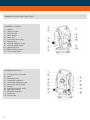
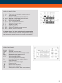
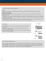
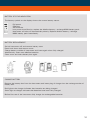
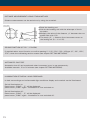
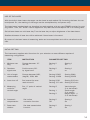
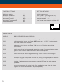
USER MANUAL
Electronic Theodolite
FET 402K-L
CONTENTS
Safety instructions
Care and cleaning
Electromagnetic acceptabilit
CE conformity
Intended use of instrument
Specific reasons for erroneous measuring results
Warranty
Exceptions from responsibilty
Important
Features / Application
Kit consists of
Technical data
Nomenclature and functions
Display indication
Operating panel
Preparation for measurement
Power on
Tilt correction function
Battery status indication
Battery replacement
Charge battery
Horizontal angle 0-set
Verticle angle
Mode conversion of horizontal rightward and leftward turning increment
Horizontal angle locked - unlocked
Slope percent mode
Angular repeated measurement
Distance measurement using stadio method
Buzz function
Automatic shut-off
Illumination of display and crosshair
Use of the laser
Initial setting
Factory settings
Setting methods
Error display
3
3
3
3
3
4
4
4
5
5
6
6
7
8
8
9
9
9
10
10
10
11
11
11
12
12
12
13
13
13
13
14
14
15
15
15
2
SAFTEY INSTRUCTIONS
• Carefully read the user manual before use.
• Do not stare into the beam. Laser beams can lead to eye injury. Directy looking into can cause
damage to your eyes.
• Do not aim laser beam directly at persons or animals.
• The laser plane should be set up above eye level.
• Use instrument for its intended tasks only.
• Do not attempt to dismantle intrument.
• Repairs should only be carried out by geo-FENNEL authorized workshops. Please contact your local
dealer.
• Do not remove warning labels or safety instructions.
• Keep instrument away from children.
• Do not use in agressive or explosive environment.
CARE AND CLEANING
Handle measuring instruments with care.
Clean with soft cloth only after any use. If necessary damp cloth with some water: If instrument is
wet clean and dry it carefully. Pack it up only if it is perfectly dry.
Transport in original container / case only.
ELECTROMAGNETIC ACCEPTABILITY (EMC)
It cannot be completely excluded that this instrument will disturb other instruments (e.g. navigation
systems); will be disturbed by other instruments (e.g. intensive electromagnetic radiation nearby
industrial facilities or radio transmitters).
CE-CONFORMITY
Instrument has CE-mark according to EN 55011:2007, EN 61000-6-1:2007.
INTENDED USE OF INSTRUMENT
Triangle, polygon and engineer measurements in the field of civil engineering as well as
cadastral survey.
3
SPECIFIC REASONS FOR ERRONEOUS MEASURING RESULTS
• Measurements through glass or plastic windows;
• dirty laser emitting windows.
• After instrument has been dropped or hit. Please check accuracy.
• Large fluctuation of temperature: If instrument will be used in cold areas after it has been
stored in warm areas (or the other way round) please wait some minutes before carrying out
measurements.
WARRANTY
This product is warranted by the manufacturer to the original purchaser to be free from defects in
material and workmanship under normal use for a period of two (2) years from the date of purchase.
During the warranty period, and upon proof of purchase, the product will be repaired or replaced
(with the same or similar model at manufacturers option), without charge for either parts or labour.
In case of a defect please contact the dealer where you originally purchased this product. The warranty will not apply to this product if it has been misused, abused or altered. Without limiting the
foregoing, leakage of the battery, bending or dropping the unit are presumed to be defects resulting
from misuse or abuse.
EXCEPTIONS FROM RESPONSIBILITY
• The user of this product is expected to follow the instructions given in the user manual. Although all
instruments left our warehouse in perfect condition and adjustment the user is expected to carry out
periodic checks of the product’s accuracy and general performance.
• The manufacturer, or its representatives, assumes no responsibility of results of a faulty or intentional usage or misuse including any direct, indirect, consequential damage, and loss of profits.
• The manufacturer, or its representatives, assumes no responsibility for consequential damage, and
loss of profits by any disaster (earthquake, storm, flood etc.), fire, accident, or an act of a third party
and/or a usage in other than usual conditions.
• The manufacturer, or its representatives, assumes no responsibility for any damage, and loss of
profits due to a change of data, loss of data and interruption of business etc., caused by using the
product or an unusable product.
• The manufacturer, or its representatives, assumes no responsibility for any damage, and loss of profits caused by usage other than explained in the user manual.
• The manufacturer, or its representatives, assumes no responsibility for damage caused by wrong
movement or action due to connecting with other products.
4
IMPORTANT! READ BELOW INSTRUCTIONS BEFORE USING YOUR INSTRUMENT
• Make a full check of the instrument before using it. Make sure that the instrument’s functions,
power, original settings and revised parameters meet your requirements before you operate it.
• To avoid direct sunlight to the instrument’s lens, never leave the instrument exposed to extreme
heat longer than necessary, or it could affect the instrument’s accuracy.
• When mounting or dismounting the instrument to or from the tripod, hold the instrument by one
hand, turn the central screw on the tripod by the other hand to prevent the instrument from falling.
If the instrument must be carried on the tripod, hold the instrument as vertically as possible. Never
carry the instrument horizontally over your shoulder. Any long distance transport should be done
with the instrument in the carrying case.
• Put the instrument into the carrying case to avoid extrusion, crash and shock during transportation.
Shockproof cushion should be necessarily put inside the carrying case during the long distance
transportation.
• Clean the dirt on the surface of the organic glass and plastic by floss or brush after using the instrument. Dry the instrument in time after use in the rain.
• Do not use harsh chemicals to clean the surface of the organic glass and plastic components. A
water dampened rag is all that is necessary.
• Use absorbent cotton or lenses tissue to clean the exposed optical parts. Handkerchief, clothes or
other things like that are forbidden for cleaning.
• The instrument should be stored in an area of low humidity and good ventilation, where the
temperature will not exceed 45ºC. It should be necessary to replace the desiccant regularly in the
carrying case.
• Always remove the alkaline / rechargeable battery before storing the instrument.
• Please contact our company if the instrument’s functions appear abnormal. Non-professional
repairers are forbidden to disassemble the instrument.
FEATURES
•
•
•
•
•
•
•
•
•
•
•
Integrated laser pointer
Coaxial laser beam integrated to the telescope.
Beam is focussable
Dual axis compenator to ensure high accuracy
2 large easy-to-read LCDs
Simultaneous reading of horizontal and vertical circle
Illumination of display
Clockwise / anti-clockwise horizontal angle reading
„0“ set or hold of horizontal circle at any desired position
„V“ circle reading in gon/degrees or % of slope
Electronic compensator
APPLICATION
Setting out alignments and footings
Inspection and control
Control of profiles, slope settings.
5
KIT CONSISTS OF
Electronic Theodlite FET 402K-L, rechargeable battery and charger, carrying container, manual
TECHNICAL DATA
Telescope
Magnification Clear objective aperture
Shortest focussing distance
30×
45 mm
1,4 m
Angle measurement
Accuracy
Shortest focussing distance
Compensator
Measuring units
Display
incremental
0,6 mgon (2“)
0,2 mgon (1“)
Dual axis compensation
400gon / 360° / mil
2 x LCD
Laser pointer (focussable)
Laser class / output power
Spot size Ø
Max. visible distance
Max. visible distance at sunlight
Deviation from collimation axis
3R
5 mm / 100 m
180 m
40 m
5“
Optical plummet
Magnification
Focussing range
3x
0,5 to ∞
Vials
Plate level
Circular level
30‘/2 mm
8‘/2 mm
Power supply
alternatively
Operating time
Theodolite
Theodolite + Laser
NiMH rechargeable battery
Alkaline batteries
35h NiMH / 40h Alkaline
24h NiMH / 30h Alkaline
Temperature range
Data interface
Dust / water protection
Tribrach
Weight
-20°C - +45°C
RS 232C
IP 54
detachable
4,5 kg
6
NOMENCLATURE AND FUNCTIONS
NOMENCLATURE (1)
1)Handle
2)Objective lens
3)Optical sight
4)Laser button
5)Plate vial
6)Communication plug
7)Battery box
8)Vertical tangent screw
9)Vertical clamp knob
10)Operating keys
11)Base locking button
12Tripod base plate
NOMENCLATURE (2)
1)Fixing screw for handle
2)Laser
3)Focusing knob
4)Telescope eyepiece
5)Horizontal tangent screw
6)Horizontal clamp knob
7)Display
8)Instrument center mark
9)Optical plummet
10)Plummet eyepiece
11)Circle vial
12)Foot screw
7
DISPLAY INDICATION
1)Ht
2V
3)
4)AVG
5)HR 6)HL
7)TILT
8)F
9)G
10)%
11)REP
12)BAT
Total value of repeated measurements
Vertical angle
Number of repeated measurements
Average of repeated measurements
Right horizontal angle
Left horizontal angle
TILT compensator function
Optional function keys
Angle unit GON
Vertical grade %
Status of repeated measurement
Battery status indication
If display shows “b” after activating tilt compensation
function, which means exceeded compensation range,
the instrument should be set on a more even surface.
OPERATING PANEL
Δ
Button
FUNC
REP
HOLD
V/%
R/L
0SET
Δ
Δ
Function
Optional function keys
Illumination switch for display screen
Repeated angle measurement
Hold horizontal angle
Vertical angle display
Vertical angle/percent display
Left/right horizontal angle measuement selection
0SET for horizontal angle
Power switch
Move cursor leftward
Move cursor rightward
Change the number that cursor shows
8
PREPARATION FOR MEASUREMENT
• Tripod
Place the tripod legs to a suitable length and tighten the locking clamps. Make sure that the
tripod is set up safely.
• Mount the instrument
Mont the instrument onto the tripod carefully, and fix it with the 5/(„ retaing bolt of the tripod.
• Adjust the vials
First adjust ciruclar vial, then adjust plate vial. The plate vial is adjusted correctly and the instrument
leveled perfectly the plate vial stays centered no matter in which direction the instrument is rotated.
• Ground point centering
The ground point can be targeted with the built-in optical plummet. Focus the target with eypiece of
the optical plummet and focus the ground point with the focussing ring.
POWER ON
• Press POWER button for 1 sec. and all symbols will be displayed
on the LCD.
• The buzzer will sound twice and the horizontal angle value and
„O-SET“ will be displayed.
• Rotate the telescope 360° to activate the vertical measuring mode
and to activate the keypad.
TILT CORRECTION FUNCTION
This theodolite is equipped with tilt compensator. The tilt angle of the instrument can be compensated automatically by the device. If the instrument is tilted too much, symbol “b” will be shown
on the display, which means the instrument exceeds the compensated range. Level the nstrument
more precisely (for activation / de-activation see (SETTING METHODS).
9
BATTERY STATUS INDICATION
The battery symbol on the display shows the current battery status.
Full power
Effective
Still effective
Low power but effective, replace the alkaline battery / recharge NiMH battery pack.
Instrument will shut off automatically shortly. Replace alkaline battery / recharge
NiMH battery pack immediately.
BATTERY REPLACEMENT
Switch instrument off and remove battery case
Press hook down and remove cover.
Charge battery outside of instrument and insert again when fully charged.
Alternatively: Insert new alkaline batteries.
Close cover and insert battery box again.
CHARGE BATTERY
Remove the battery box from the instrument and insert plug of charger into the recharge socket of
battery box.
Red light at the charger indicates that batteries are being charged.
Green light at charger indicates that batteries have been fully charged.
Before first use of the instrument fully charge the rechargeable batteries.
10
HORIZONTAL ANGLE OSET (OSET)
Aim at target A using crosshair of the telescope.
Press 0SET key once to set reading of horizontal
angle 0°00’ 00”:
0SET key is only effective for the horizontal angle.
Horizontal angle can be set 0 at any time except in
holding status (HOLD key).
VERTICAL ANGLE
Press button „FUNC“
Press button „V%“ (confirm „O-SET“)
Indication „Step 1“ first rotation (A)
Confirm adjustment via collimator with „O-SET“
Rotate
Indication „Step 2“ second rotation (B)
Confirm adjustment via collimator with „O-SET“
MODE CONVERSION OF HORIZONTAL RIGHTWARD (HR) AND
LEFTWARD (HL) TURNING INCREMENT
Aim at target “A” using crosshair of the telescope.
Press R/L key, transform horizontal angle mode HR into
the mode HL.
Measuring with mode HL.
R/L key is of no effect to the vertical angle.
Press R/L key again, transform mode HL into mode HR.
11
HORIZONTAL ANGLE LOCKED - UNLOCKED
Turn the tangent knob and place the required horizontal angle.
Press HOLD button to hold the current value of horizontal angle.Value will flash while this
function is active.
Press HOLD button again to release the value.
SLOPE PERCENT MODE
Measuring in angle mode, the vertical angle could be transformed into percent of grade.
• Press button „V%“ to to switch from vertical angular measurement shown in degrees to percent.
• The maximum % value will be 99.999 %; exceeding this display will show „- - - - -“.
ANGULAR REPEATED MEASUREMENT
1Press FUNC key.
2Press REP key to enter into repeated mode.
3Aim at target A and press 0SET key once to set the first target
reading 0°00’ 00”.
4Turn the horizontal tangent knob to aim at the second target B.
5Press HOLD key to hold the horizontal angle and store in the
instrument.
6Turn the horizontal tangent knob to aim at target A again. Press
R/L key to release the angle and keep the status.
7Turn the horizontal tangent knob to aim at the target B again.
8Press HOLD key to hold the horizontal angle and store in the
instrument. Double and average angle-value will be shown on
the display.
9Repeat steps 7 and 8 according to measuring requirements.
10Back to standard angular measurement, press FUNC key,
then press HOLD key.
The reading of horizontal angle could reach max. ±2000°00’ 00” when
measuring in „Plate left” or “Plate right” mode. The five-seconds reading
could reach at least ±1999°59’ 59”.
The repeated measurement should be limited to15 times.
Error E04 will be shown on the display when measured error every time
exceeds or equals ±30” during the repeated measurement, go back to
step 3.
12
DISTANCE MEASUREMENT USING STADIA METHOD
Distance measurement can be carried out by using the crosshair.
• Read the levelling rod
• Aim at the levelling rod with the telescope of the instrument.
• Mulitply the value of the distance „d“ between the two
stadia hairs with 100.
• The result „D“ = distance from instrument centre to
the levellig rod (D = d x 100).
SOUND FUNCTION (AT 90° / 100GON)
If required select sound function to confirm passing 0 / 100 / 200 / 300 / 400gon (0°, 90°, 180°,
270°) when the collimating section rotates (see chapter SETTING METHODS).
AUTOMATIC SHUT-OFF
Automatic shut off can be selected when instrument is not in use permanently.
Available intervals: 10 to 30 minutes (see chapter SETTING METHODS).
ILLUMINATION OF DISPLAY AND CROSSHAIR
In dark surroundings and unfavourable light conditions display and crosshair can be illuminated:
Switch illumination on:
Press button „FUNC“ - „F“ will be displayed press button „FUNC“ again - illumination is now switched on.
Switch illumination off:
Press button „FUNC“ - „F“ will be displayed press button „FUNC“ again - illumination is now switched off.
13
USE OF THE LASER
With the built-in laser beam the target can be aimed at and marked. By focussing the laser dot can
be adjusted. So, the marking of the target can be acomplished by one person only.
The laser beam is pulsed and can therefore be used together with any geo-FENNEL receiver for rotating lasers. Thus, FET 402K-L can be applied for any task that would require use of a rotating laser.
Switch laser beam on with laser key.Turn the laser key to adjust brightness of the laser beam.
Smallest diameter of laser dot will be achieved if laser beam is focussed.
By means of the laser beam all measuring tasks can be acomplished and will be visualized to the
user.
INITIAL SETTING
The instrument supplies multi-functions for your selection to meet different requires of
measuring configuration.
ITEMINSTRUCTION
PARAMETER SETTING
1Minimum rea- Change between 10“
dingand 20“
Setting 0
10“
Setting 1
20“
2Quadrant Confirm every 90°
signal toneby signal tone
Setting 0
off
Setting 1
on
3Unit of angle Change between DEG,
measurement (degree), GON, MIL
Setting 0/DEG
Setting 1/GON
Setting 2/MIL
Setting 3/DEG
4Auto shut-off Set interval for auto-
matic shut-off
Setting 0/Off
Setting 2/20 min.
Setting 1/10 min. Setting 3/30 min.
5Measuring Set „0“ point of vertical
Setting O
mode forangle
vertical angle Setting 1
Setting 2
Vertical angle
(0 in horizontal)
Zenith angle
(0 in zenith)
Height angle +/(0 in hoirzontal)
6
AutomaticSet incline
compensationcorrection function
Setting 0
Off
Setting 1
On
7Data trans- Set data transmission
missionfunction
Setting 0
Off
Setting 1
On
14
1“
OFF
GON
OFF
ZENITH ANGLE
OFF
OFF
Switch instrument o.
Press „FUNC“ and then on/off key.
Press buttons
and
to select
required values (1 - 7).
The parameters set will be available
even in case instrument is switched off.
Δ
Minimum reading Quadrant signal tone
Unit of angle measurement
Automatic shut-off
Vertical angle measuring mode
Automatic compensation
Data transmission
SETTTING METHODS
Δ
FACTORY SETTINGS
ERROR DISPLAY
DISPLAY
ERROR DESCRIPTION AND DISPOSAL
B
Vertical compensator out of compensating range. Level the instrument again.
E00
Collimate rotating is too fast. Press 0SET key to set 0. If “E00” is shown again
instrument needs to be repaired.
E01
Telescope turning is too fast. Press V/% key to set 0 for the vertical plate
specification.
E02
Interior error of the horizontal angle measuring system. Power on the instrument
again. If error is shown again instrument needs to be repaired.
E03
Interior error of the vertical angle measuring system. If error is shown again
instrument needs to be repaired.
E04
Difference between every value exceeds 30“ during the angle repeated measurement.Press 0SET key and measure repeatedly.
E05
Number of angle repeated measurement exceeds 15. Press key and measure
repeatedly.
E06
Errors during process of vertical angle 0set or adjusting 0set when the clamp
angle to the horizon exceeds 45°. Adjust repeatedly.
15
geo-FENNEL GmbH
Kupferstraße 6
D-34225 Baunatal
Tel. +49 561 49 21 45
Fax +49 561 49 72 34
Email: [email protected]
www.geo-fennel.de
All instruments subject to technical changes.
08/2011