1
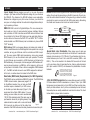
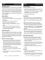
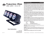
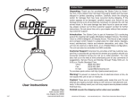
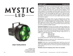
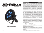
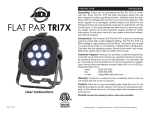
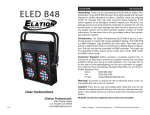
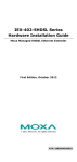
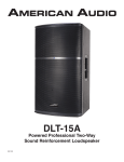
SP4LED Introduction
Unpacking: Thank you for purchasing the SP4LED by American DJ®.
Every SP4LED has been thoroughly tested and has been shipped in
perfect operating condition. Carefully check the shipping carton for
damage that may have occurred during shipping. If the carton appears
to be damaged, carefully inspect your fixture for any damage and be
sure all accessories necessary to operate the unit has arrived intact. In
the case damage has been found or parts are missing, please contact
our toll free customer support number for further instructions. Do not
return this unit to your dealer without first contacting customer support.
Introduction: The American DJ® SP4LED is part of a continuing pur-
suit to create high quality intelligent lighting and lighting control. The
SP4LED is a 4-Channel DMX switch pack designed to turn LED fixtures
on and off using a universal DMX controller. Up to 128 SP4LEDs may
be daisy-chained in one DMX chain. There are 8 power inputs on the
front of the controller to plug your lighting fixtures into.
Customer Support: American DJ provides a customer support line,
to provide set up help and to answer any question should you encounter problems during your set up or initial operation. You may also visit
us on the web at www.AmericanDJ.com for any comments or suggestions. Service Hours are Monday through Friday 8:00 a.m. to 4:30 p.m.
Pacific Standard Time.
Voice:
(323) 582-3322
Fax: (323) 582-3108
E-mail: [email protected]
Warning! To prevent or reduce the risk of electrical shock or fire, do
not expose this unit to rain or moisture.
Caution! There are no user serviceable parts inside this unit. Do not
User Instructions
12/11
attempt any repairs yourself, doing so will void your manufactures warranty. In the unlikely event your unit may require service please contact
American DJ.
PLEASE recycle the shipping carton when ever possible.
©American
DJ® - www.Americandj.com - SP4LED User Manual Page 2
SP4LED General Instructions
To optimize the performance of this product, please read these
operating instructions carefully to familiarize yourself with the basic
operations of this unit. These instructions contain important safety
information regarding the use and maintenance of this unit. Please
keep this manual with the unit, for future reference.
SP4LED
Features
•
•
•
•
•
•
Five Operating Modes
Built in Microphone
DMX-512 protocol
3-Pin DMX Connection
Up to 128 SP4LEDs may be Daisy-Chained together via DMX
3 DMX Channel Modes: 3 Channel Mode, 5 Channel Mode, & 7 Channel Mode
• ADJ LED RC Compatiable (Sold Separately)
SP4LED
Warranty Registration
The SP4LED carries a one year limited warranty. Please fill out the
enclosed warranty card to validate your purchase. All returned service
items whether under warranty or not, must be freight pre-paid and
accompany a return authorization (R.A.) number. The R.A. number
must be clearly written on the outside of the return package. A brief
description of the problem as well as the R.A. number must also be
written down on a piece of paper included in the shipping carton. If
the unit is under warranty, you must provide a copy of your proof of
purchase invoice. You may obtain a R.A. number by contacting our
customer support team on our customer support number. All packages returned to the service department not displaying a R.A. number
on the outside of the package will be returned to the shipper.
©American
DJ® - www.Americandj.com - SP4LED User Manual Page 3
SP4LED
Safety Precautions
•To reduce the risk of electrical shock or fire, do not expose this unit rain or moisture
•Do not spill water or other liquids into or on to your unit.
•Be sure that the local power outlet match that of the required volt-
age for your unit.
•Do not attempt to operate this unit if the power cord hasbeen
frayed or broken. Do not attempt to remove or break off the ground
prong from the electrical cord. This prong is used to reduce the risk of electrical shock and fire in case of an internal short.
•Disconnect from main power before making any type of connection.
• Do not remove the cover under any conditions. There are no user serviceable parts inside.
•Never operate this unit when it’s cover is removed.
•Never plug this unit in to a dimmer pack
•Always be sure to mount this unit in an area that will allow proper ventilation. Allow about 6” (15cm) between this device and a wall.
•Do not attempt to operate this unit, if it becomes damaged.
•This unit is intended for indoor use only, use of this product out`
doors voids all warranties.
•During long periods of non-use, disconnect the unit’s main power.
•Always mount this unit in safe and stable matter.
•Power-supply cords should be routed so that they are not likely to
be walked on or pinched by items placed upon or against them, paying particular attention to the point they exit from the unit.
• Cleaning -The fixture should be cleaned only as recommended by the manufacturer. See page 15 for cleaning details.
•Heat -The appliance should be situated away from heat sources such as radiators, heat registers, stoves, or other appliances (including amplifiers) that produce heat.
•The fixture should be serviced by qualified service personnel when:
A. The power-supply cord or the plug has been damaged.
B. Objects have fallen, or liquid has been spilled into the appliance.
C. The appliance has been exposed to rain or water.
D. The appliance does not appear to operate normally or exhibits a marked change in performance.
©American
DJ® - www.Americandj.com - SP4LED User Manual Page 4
SP4LED
Set Up
Power Supply: Before plugging your unit in, be sure the source
voltage in your area matches the required voltage for your American
DJ® SP4LED. The American DJ® SP4LED voltage is user selectable.
Because line voltage may vary from venue to venue, you should be
sure your unit voltage matches the wall outlet voltage before attempting to operate you fixture.
SOUND
REMOTE
CONTROL
INPUT
INPUT
OUTPUT
cables. Do not use the ground lug on the XLR connector. Do not connect the cable’s shield conductor to the ground lug or allow the shield
conductor to come in contact with the XLR’s outer casing. Grounding
the shield could cause a short circuit and erratic behavior.
COMMON
2
REMOTE
CONTROL
INPUT
SOUND
3
Data Cable (DMX Cable) Requirements (For DMX Operation):
The SP4LED can be controlled via DMX-512 protocol. The SP4LED has
3 DMX channel modes, please see pages 8-10
for the different modes. Your unit and your DMX
controller require a standard 3-pin XLR connector for data input and data output (Figure 1). We
recommend Accu-Cable DMX cables. If you are
making your own cables, be sure to use standard
110-120 Ohm shielded cable (This cable may be
purchased at almost all pro lighting stores). Your
cables should be made with a male and female
Figure 1
XLR connector on either end of the cable. Also
remember that DMX cable must be daisy chained and cannot be split.
©American
DJ® - www.Americandj.com - SP4LED User Manual Page 5
1
DMX512 OUT
3-PIN XLR
INPUT
2
DMX +
3
OUTPUT
3
DMX -
1
2
SOUND
XLR Female Socket
XLR Male Socket
1 Ground
2 Cold
2 Cold
1 Ground
DMX512 IN
3-PIN XLR
REMOTE
CONTROL
INPUT
INPUT
3
Figure 2
OUTPUT
1
2
Termination redu
avoids signal tra
and interference.
to connect a DMX
120 Ohm 1/4 W)
and PIN 3 (DMX
XLR Pin Configuration
Pin 1 = Ground
Pin 2 = Data Compliment (negative)
3 Hot
Figure 3
POWER
1
POWER
Set Up
Notice: Be sure
to DMX512
follow figures two and three when making your own
DMX+,DMX-,COMMON
DMX-512: DMX is short for Digital Multiplex. This is a universal pro-
tocol used as a form of communication between intelligent fixtures
and controllers. A DMX controller sends DMX data instructions from
the controller to the fixture. DMX data is sent as serial data that travels from fixture to fixture via the DATA “IN” and DATA “OUT” XLR terminals located on all DMX fixtures (most controllers only have a DATA
“OUT” terminal).
DMX Linking: DMX is a language allowing all makes and models of
different manufactures to be linked together and operate from a single
controller, as long as all fixtures and the controller are DMX compliDMX512
ant. To ensure proper DMX data transmission,
when
using several
DMX+,DMX-,COMMON
DMX fixtures try to use the shortest cable path possible. The order
in which fixtures are connected in a DMX line does not influence the
DMX addressing. For example; a fixture assigned a DMX address of 1
may be placed anywhere in a DMX line, at the beginning, at the end,
or anywhere in the middle. When a fixture is assigned a DMX COMMON
address
of 1, the DMX controller knows to send DATA
assigned to address
1
DMX +
DMX512 OUT
XLR
DMX to that unit, no matter where it is located in the3-PIN
DMX
chain.
POWER
SP4LED
3 Hot
Pin 3 = Data True (positive)
POWER
POWER
Special Note: Line Termination. When longer runs of cable are
3
1
2
used, you may need to use a terminator on the last unit to avoid erratic
behavior. A terminator is a 110-120 ohm 1/4 watt resistor which is connected between pins 2 and 3 of a male XLR connector (DATA + and
DATA -). This unit is inserted in the female XLR connector of the last
unit in your daisy chain to terminate the line. Using a cable terminator
(ADJ part number Z-DMX/T) will decrease the possibilities of erratic
behavior.
Termination reduces signal errors and
DMX512 IN
3-PIN XLR
3
avoids signal transmission problems
and interference. It is always advisable
to connect a DMX terminal, (Resistance
120 Ohm 1/4 W) between PIN 2 (DMX-)
and PIN 3 (DMX +) of the last fixture.
1
2
Figure 4
5-Pin XLR DMX Connectors. Some manufactures use 5-pin DMX512 data cables for DATA transmission in place of 3-pin. 5-pin DMX
fixtures may be implemented in a 3-pin DMX line. When inserting standard 5-pin data cables in to a 3-pin line a cable adaptor must be used,
these adaptors are readily available at most electric stores. The chart
below details a proper cable conversion.
3-Pin XLR to 5-Pin XLR Conversion
Conductor
3-Pin XLR Female (Out)
5-Pin XLR Male (In)
Ground/Shield
Pin 1
Pin 1
Data Compliment (- signal)
Pin 2
Pin 2
Data True (+ signal)
Pin 3
Pin 3
Not Used
Do Not Use
Not Used
Do Not Use
©American
DJ® - www.Americandj.com - SP4LED User Manual Page 6
SP4LED
Operating Instructions
SP4LED
Operating Instructions
LED Display On/Off:
Sound Active Mode:
Operating Modes:
Program Mode:
To set the LED display to turn off after 20 seconds, press the MODE
and DOWN buttons simultaneously. Now the display will disappear
after 20s. Press any button to turn the display on again. Be advised
though that the display will turn off automatically after 20 seconds. If
your want the display to stay on at all times press the MODE and UP
buttons simultaneously.
You can use the SP4LED in five ways:
• Sound-Active mode - The unit will react to sound, chasing through the
built in programs.
• Program Mode - There are 12 programs to choose from.
• Auto Mode - This will run an automatic program
• Manual Dimmer Output mode - Adjust the intensity of all output channels.
• DMX control mode - This function will allow you to control each
individual fixtures traits with a standard DMX 512 controller such as
as the American DJ® Show Designer™.
Master-Slave Operation:
This function will allows you to link units together to run in a MasterSlave mode. In Master-Slave operation one unit will act as the controlling
unit and the others will react to the controlling units built-in programs.
Any unit can act as a Master or as a Slave however, only one unit can be
programmed to act as the “Master.”
Master-Slave Connections and Settings:
1. Daisy chain your units via the XLR connector on the rear of the unit. Use standard XLR microphone cables to link your units together. Remember that the Male XLR connector is the input and the Female XLR connector is the ouput. The first unit in the chain (master) will use the female XLR connector only. The last unit in the chain will use the male XLR connector only.
2. Set the “Master” unit to your desired mode of operation.
3. For the “Slave” unit(s), press the UP or DOWN buttons until “SLAv” is displayed.
4. Connect the “Slave” unit or units and they will automatically start to
follow the “Master.”
©American
DJ® - www.Americandj.com - SP4LED User Manual Page 7
In this mode the SP4LED will react to sound.
1. Plug the fixture in and press the MODE button until “SU.XX” is dis-
played. “XX” represents the sound sensitivity setting. “01” is the least sound sensitive, and “31” is the most sound sensitive. Use the UP and DOWN buttons to adjust the sound sensitivity.
2. The fixture will now change via sound.
In this mode the SP4LED will run 1 of 12 factory installed programs
1. Plug the fixture in and press the MODE button until “Pr.XX” is display- ed. “XX” = 01-12. There are 12 different preset programs to choose
from.
2. Press the UP or DOWN buttons to find your desired program.
3. When you have found your desired program press the SET UP but- ton, “SP.XX” will now be displayed. In this menu you can adjust the running speed of the program, “XX” = 1-99. 1 is the slowest speed, 99 the fastest speed. Note: The speed can only be adjusted in Programs 2-12.
4. When “Pr.01” is displayed you can press the SET UP button to select different output channel combinations. When you press the SET UP button, “CG.XX” will be displayed. Use the UP or DOWN buttons to
change the combinations. There are 15 combinations to choose from.
Manual Dimmer Output Mode:
In this mode the intensity of each output channel can be adjusted
1. Plug the fixture in and press the MODE button until “1.XXX” is displayed. “XXX” represents the displayed intensity number, while “1” represents Output Channel 1.
2. To change the output channel, press the SET UP button. When you have found the output channel you would like to adjust, use the UP and DOWN buttons to adjust the intensity.
2. The intensity can be adjusted from “00” (no output) to “255” (full intensity).
Auto Mode:
1. Plug the fixture in and press the MODE button until “AUTO” is displayed. Auto mode is now activated.
2. The auto mode run speed can be adjusted by pressing the SET UP button, “SP.XX” will now be displayed. “XX” = 1-99. 1 is the slowest ©American
DJ® - www.Americandj.com - SP4LED User Manual Page 8
SP4LED
Operating Instructions
speed, 99 the fastest speed.
DMX Mode:
Operating through a DMX controller gives the user the freedom to create their own programs tailored to their own individual needs. This function also allows you to use your fixtures as spot lights. The SP4LED has
3 DMX Channel modes: 3 Channel mode, 5 Channel mode, and a 7
Channel mode. See pages 12-14 for each modes’ DMX traits.
1. This function will allow you to control each individual fixture’s traits with a standard DMX 512 controller.
2. To run your fixture in DMX mode, plug in the fixture via the XLR connections to any standard DMX controller. Select your desired DMX channel mode, and then press the UP or DOWN buttons to adjust the DMX address.
3. To select your desired DMX channel mode, press the MODE button until d-PX is displayed. “X” represents the displayed channel mode.
• To run the 3 Channel Mode, press the UP or DOWN buttons until “d-P1” is displayed. This is the DMX addressing for the 3 Channel Mode.
• To run the 5 Channel Mode, press the UP or DOWN buttons until “d-P2” is displayed. This is the DMX addressing for the 5 Channel Mode.
• To run the 7 Channel Mode, press the UP or DOWN buttons until “d-P3” is displayed. This is the DMX addressing for the 7 Channel Mode.
4. Please see pages 12-14 for DMX values and traits.
Infrared Receiver:
This function is used to activate and deactivate the infrared receiver.
When this function is activated you can control the SP4LED using the
ADJ LED RC (Remote Control). Please see the user manual for controls and functions.
1. Plug the fixture in and press the MODE button until “AUTO” is dis-
played.
2. Press the SET UP button until “IrXX” is displayed. “XX” represents either “on” or “oF”.
3. Press the UP or DOWN buttons to either activate the remote function (On) or deactivate it (Off).
©American
DJ® - www.Americandj.com - SP4LED User Manual Page 9
SP4LED
ADJ LED RC Operating Instructions
The ADJ LED RC infrared remote (sold seperately) has many differnet
functions and gives you complete control of your SP4LED. To control
the your desired fixture you must aim the controller at the front of the
fixture and be no more the 30 feet away. To use the ADJ LED RC you
must first activate the fixtures infrared receiver, to activate the receiver please see the instructions on page 9.
BLACKOUT - Pressing this button will blackout the fixture.
AUTO RUN - This button will run an automatic program. You can
control the speed of the Auto Run by pressing the SPEED button first
and then pressing the “+” and “-” buttons.
PROGRAM SELECTION - This button will let you access the units
built-in programs. Press this button and then press the “+” or “-” to
navigate through the built-in programs. You can control the speed of
the program by pressing the SPEED button and then pressing the “+”
and “-” buttons. When in Program 1, pressing the SPEED button will
let select 1 of 15 output channel combinations. Use the “+” and “-”
buttons scroll through the different combinations.
FLASH - This button will not work with the SP4LED.
SPEED - Press this button and use the “+” & “-” buttons to adjust the
speed of the Auto run.
DMX MODE - This button will let you select which DMX mode you
want to use. Some fixtures will come with different DMX channel
modes. This button will switch between the different modes. Please
see pages 13-17 for DMX modes, values, and traits.
SOUND ACTIVE - This button activates sound active mode. Use the
“+” and “-” buttons to adjust the sound sensitivity.
SLAVE - This designates the fixture as a slave fixture in a master/
slave configuration.
SET ADDRESS - Press this button to set the DMX address. Press
this button first, then press the numbers to set the address.
Example: Set DMX Address 1 Press “S-0-0-1”
Set DMX Address 245 Press “S-2-4-5”
1/2/3/4 - Press the 1/2/3/4 buttons to choose either of the four output
channels and then press the “+” or “-” to adjust the intensity. 1 is for
©American
DJ® - www.Americandj.com - SP4LED User Manual Page 10
SP4LED
ADJ LED RC Operating Instructions
output channel 1, 2 is output channel 2, 3 is output channel 3, and 4
is output channel 4.
“+” and “-” - Use these buttons to adjust the speed of the Auto Run,
sound sensitivity, and program selection.
DMX Control:
Operating through an DMX controller gives the user the freedom to
create their own programs tailored to their own individual needs.
Follow the directions below to set your DMX Mode and address.
1. Before connecting to an DMX controller, your fixture has different DMX channel modes, please select your desired mode by press-
ing the DMX Mode button, then using the “+” or “-” buttons to
scroll through the DMX Channel Modes. Set the mode before you
address the fixture. See the bottom of this page for the DMX
modes.
SP4LED
• If Output Channel 2 is lit, you are in DMX Mode 2: 5 DMX
Channels.
• If Output Channel 3 is lit, you are in DMX Mode 3: 7 DMX
Channels.
SP4LED
Channel
2
3. After the output channel LED’s have flashed, output channel 1 LED will remain lit, press the first number in your desired address.
4. After you have pressed the first number in your address, output channel 2’s LED will light. Now press the button of the second num-
ber in your desired address.
6. Now you may connect the fixture via the XLR connections to any standard DMX controller. Please see pages 12-14 to for a detailed descriptions of the DMX modes, values, and traits.
• If Output Channel 1 is lit, you are in DMX Mode 1: 1 DMX
Channel.
©American
DJ® - www.Americandj.com - SP4LED User Manual Page 11
1 Channel - DMX Values & Functions
Value
1
2. After you have selected your mode, set the DMX address for the fixture by pressing the “S” button. When the “S” button is pressed
the output channel LED’s will flash 2-3 times. Use the number but-
tons to press in your desired address.
5. After you have pressed the second number in your address, output channel 3’s LED will light. Now press the third and last number in your desired address. After all three numbers have been entered, the output channel LED’s will flash 2-3 times to indicate that the DMX address is correct. The unit will then automatically enter DMX mode. If the DMX address is incorrect the output channel 1 LED will be lit.
ADJ LED RC Operating Instructions
3
0 - 255
Function
MASTER DIMMER
0% - 100%
PROGRAMS
DIMMING
PROGRAM 1
PROGRAM 2
PROGRAM 3
PROGRAM 4
PROGRAM 5
PROGRAM 6
PROGRAM 7
PROGRAM 8
PROGRAM 9
PROGRAM 10
PROGRAM 11
AUTO RUN
SOUND ACTIVE
PROGRAM SPEED/SOUND SENSITVITY
1 - 255
PROGRAM SPEED SLOW - FAST
1 - 255
SOUND SENSITIVITY
LEAST SENSITIVE - MOST SENSITIVE
0-9
10 - 29
30 - 49
50 - 69
70 - 89
90 - 109
110 - 129
130 - 149
150 - 169
170 - 189
190 - 209
210 - 229
230 - 249
250 - 255
• When using Channel 2 values 10-249, Channel 3 will control the speed of
the programs.
• When using Channel 2 values 250-255, Channel 3 will control the sound
sensitivity.
©American
DJ® - www.Americandj.com - SP4LED User Manual Page 12
SP4LED
Channel
Value
1
2
3
0 - 255
0-9
10 - 29
30 - 49
50 - 69
70 - 89
90 - 109
110 - 129
130 - 149
150 - 169
170 - 189
190 - 209
210 - 229
230 - 249
250 - 255
1 - 255
1 - 255
4
1 - 255
5
1 - 255
5 Channel - DMX Values & Functions
Function
MASTER DIMMER
0% - 100%
PROGRAMS
DIMMING
PROGRAM 1
PROGRAM 2
PROGRAM 3
PROGRAM 4
PROGRAM 5
PROGRAM 6
PROGRAM 7
PROGRAM 8
PROGRAM 9
PROGRAM 10
PROGRAM 11
AUTO RUN
SOUND ACTIVE
PROGRAM SPEED/SOUND SENSITVITY
PROGRAM SPEED SLOW - FAST
SOUND SENSITIVITY
LEAST SENSITIVE - MOST SENSITIVE
OUTPUT CHANNELS 1 & 2 DIMMER
DIM - BRIGHT
OUTPUT CHANNELS 3 & 4 DIMMER
DIM - BRIGHT
• When using Channel 2 values 0-9, Channel 4 & Channel 5 will control the
dimming of output channels 1-4.
• When using Channel 2 values 10-249, Channel 3 will control the speed of
the programs.
• When using Channel 2 values 250-255, Channel 3 will control the sound
sensitivity.
©American
DJ® - www.Americandj.com - SP4LED User Manual Page 13
SP4LED
Channel
7 Channel - DMX Values & Functions
Value
1
2
3
0 - 255
0-9
10 - 29
30 - 49
50 - 69
70 - 89
90 - 109
110 - 129
130 - 149
150 - 169
170 - 189
190 - 209
210 - 229
230 - 249
250 - 255
1 - 255
1 - 255
4
1 - 255
5
1 - 255
6
1 - 255
7
1 - 255
Function
MASTER DIMMER
0% - 100%
PROGRAMS
DIMMING
PROGRAM 1
PROGRAM 2
PROGRAM 3
PROGRAM 4
PROGRAM 5
PROGRAM 6
PROGRAM 7
PROGRAM 8
PROGRAM 9
PROGRAM 10
PROGRAM 11
AUTO RUN
SOUND ACTIVE
PROGRAM SPEED/SOUND SENSITVITY
PROGRAM SPEED SLOW - FAST
SOUND SENSITIVITY
LEAST SENSITIVE - MOST SENSITIVE
OUTPUT CHANNEL 1 DIMMER
DIM - BRIGHT
OUTPUT CHANNEL 2 DIMMER
DIM - BRIGHT
OUTPUT CHANNEL 3 DIMMER
DIM - BRIGHT
OUTPUT CHANNEL 4 DIMMER
DIM - BRIGHT
• When using Channel 2 values 0-9, Channel 4 - Channel 7 will control the
dimming of output channels 1-4.
• When using Channel 2 values 10-249, Channel 3 will control the speed of
the programs.
• When using Channel 2 values 250-255, Channel 3 will control the sound
sensitivity.
©American
DJ® - www.Americandj.com - SP4LED User Manual Page 14
SP4LED
Fuse Replacement
Disconnect from the main power supply. Insert a standard flat head
screw driver in to the fuse holder housing, located on the front of the
unit. Turn the screwdriver in counter-clockwise direction to remove
the fuse holder. Remove the old fuse and discard it, replace the fuse
with the same type. Insert the fuse back into it’s housing.
SP4LED
Trouble Shooting
Listed below are a few common problems the user may encounter,
with solutions.
No power output from the unit;
1.
Be sure the external fuse has not blown. The fuse is located on the rear panel of the unit.
2. Be sure the fuse holder is completely and properly seated.
Unit not responding to DMX:
1. Check that the DMX cables are connected properly and are wired correctly (pin 3 is “hot”; on some other DMX devices pin 2 may be ‘hot’). Also, check that all cables are connected to the right connectors; it does matter which way the inputs and outputs are connected.
Unit does not respond to sound:
1. Quiet or high pitched sounds will not activate the unit.
2. Make sure that you are in Sound Active mode.
SP4LED
Cleaning
Due to fog residue, smoke, and dust cleaning the internal and external optical lenses must be carried out periodically to optimize light
output.
1. Use normal glass cleaner and a soft cloth to wipe down the
outside casing.
2. Clean the external optics with glass cleaner and a soft cloth
every 20 days.
3. Always be sure to dry all parts completely before plugging
the unit back in.
Cleaning frequency depends on the environment in which the fixture
operates (i.e. smoke, fog residue, dust, dew).
©American
DJ® - www.Americandj.com - SP4LED User Manual Page 15
SP4LED
Warranty
MANUFACTURER’S LIMITED WARRANTY
A. American DJ, Inc. hereby warrants, to the original purchaser, American DJ and American
Audio products to be free of manufacturing defects in material and workmanship for a prescribed
period from the date of purchase (see specific warranty period on reverse). This warranty shall be
valid only if the product is purchased within the United States of America, including possessions
and territories. It is the owner’s responsibility to establish the date and place of purchase by acceptable evidence, at the time service is sought.
B.
For warranty service you must obtain a Return Authorization number (RA#) before
sending back the product. Contact American DJ, Inc. Service Department at 800-322-6337. Send
the product only to the American DJ, Inc. factory. All shipping charges must be pre-paid. If the
requested repairs or service (including parts replacement) are within the terms of this warranty,
American DJ, Inc. will pay return shipping charges only to a designated point within the United
States. If the entire instrument is sent, it must be shipped in it’s original package. No accessories
should be shipped with the product. If any accessories are shipped with the product, American DJ,
Inc. shall have no liability whatsoever for loss of or damage to any such accessories, nor for the
safe return thereof.
C. This warranty is void if the serial number has been altered or removed; if the product is
modified in any manner which American DJ, Inc. concludes, after inspection, affects the reliability
of the product; if the product has been repaired or serviced by anyone other than the American DJ,
Inc. factory unless prior written authorization was issued to purchaser by American DJ, Inc.; if the
product is damaged because not properly maintained as set forth in the instruction manual.
D.
This is not a service contract, and this warranty does not include maintenance, cleaning
or periodic check-up. During the period specified above, American DJ, Inc. will replace defective
parts at its expense with new or refurbished parts, and will absorb all expenses for warranty service
and repair labor by reason of defects in material or workmanship. The sole responsibility of American DJ, Inc. under this warranty shall be limited to the repair of the product, or replacement thereof,
including parts, at the sole discretion of American DJ. All products covered by this warranty were
manufactured after January 1, 1990, and bear identifying marks to that effect.
E.
American DJ, Inc. reserves the right to make changes in design and/or improvements
upon its products without any obligation to include these changes in any products theretofore manufactured. No warranty, whether expressed or implied, is given or made with respect to any accessory supplied with products described above. Except to the extent prohibited by applicable law, all
implied warranties made by American DJ, Inc. in connection with this product, including warranties
of merchantability or fitness, are limited in duration to the warranty period set forth above. And no
warranties, whether expressed or implied, including warranties of merchantability or fitness, shall
apply to this product after said period has expired. The consumer’s and/or Dealer’s sole remedy
shall be such repair or replacement as is expressly provided above; and under no circumstances
shall American DJ, Inc. be liable for any loss or damage, direct or consequential, arising out of the
use of, or inability to use, this product. This warranty is the only written warranty applicable to American DJ and American Audio Products and supersedes all prior warranties and written descriptions of warranty terms and
conditions heretofore published.
MANUFACTURER’S LIMITED WARRANTY PERIODS:
• All American Audio Products = 1-year (365 day) Limited Warranty (except V-Plus Series Amplifiers)
• All American Audio V-Plus Series Amplifiers = 3-year (1095 day) Limited Warranty
• American DJ Lighting and American DJ Branded Products = 1-year (365 day) Limited Warranty
(Such as: Special Effect Lighting, Intelligent Lighting, UV lighting, Strobes, Fog Machines, Bubble
Machines, Mirror Balls, Par Cans, Trussing, Lighting Stands etc. excluding Laser Products, lamps,
and Star Tec Series)
• American DJ Laser Products and Star Tec Products = 90-Day Limited Warranty
• American DJ L.E.D. Products = 2-year (730 day) Limited Warranty (excluding motors which have a
1-year (365 day Limited Warranty)
©American DJ® - www.Americandj.com - SP4LED User Manual Page 16
SP4LED
©American
Notes
DJ® - www.Americandj.com - SP4LED User Manual Page 17
SP4LED
©American
Notes
DJ® - www.Americandj.com - SP4LED User Manual Page 18
SP4LED
Specifications
Model: SP4LED
SPECIFICATIONS:
Working Position: Any safe working position
Voltage: 120V/60Hz or 240V/50Hz
Fuse:
5A per Channel, Total 10A Max
Weight: 4.5lbs./ 2.1Kgs.
Dimensions: 10.5” (L) x 7.75” (W) x 3” (H)
262 x 192 x 74mm
DMX Channels:
3 DMX Modes: 3 Channel Mode, 5 Channel Mode, & 7 Channel Mode Warranty:
1 Year (365 days)
Please Note: Specifications and improvements in the design of
this unit and this manual are subject to change without any prior
written notice.
©American
DJ® - www.Americandj.com - SP4LED User Manual Page 19
©American DJ Supply
American DJ World Headquarters:
6122 S. Eastern Ave. Los Angeles, CA 90040 USA
Tel: 323-582-2650 / Fax: 323-725-6100
Web: www.americandj.com / E-mail: [email protected]
American DJ Europe
Junostraat 2
6468 EW Kerkrade
Netherlands
[email protected] / www.americandj.eu
Tel: +31 45 546 85 00 / Fax: +31 45 546 85 99