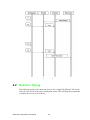
1
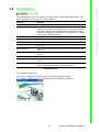
User Manual Advantech LogixView (WinCE) Copyright The documentation and the software included with this product are copyrighted 2007 by Advantech Co., Ltd. All rights are reserved. Advantech Co., Ltd. reserves the right to make improvements in the products described in this manual at any time without notice. No part of this manual may be reproduced, copied, translated or transmitted in any form or by any means without the prior written permission of Advantech Co., Ltd. Information provided in this manual is intended to be accurate and reliable. However, Advantech Co., Ltd. assumes no responsibility for its use, nor for any infringements of the rights of third parties, which may result from its use. Acknowledgements Intel and Pentium are trademarks of Intel Corporation. Microsoft Windows and MS-DOS are registered trademarks of Microsoft Corp. All other product names or trademarks are properties of their respective owners. Product Warranty (2 years) Advantech warrants to you, the original purchaser, that each of its products will be free from defects in materials and workmanship for two years from the date of purchase. This warranty does not apply to any products which have been repaired or altered by persons other than repair personnel authorized by Advantech, or which have been subject to misuse, abuse, accident or improper installation. Advantech assumes no liability under the terms of this warranty as a consequence of such events. Because of Advantech’s high quality-control standards and rigorous testing, most of our customers never need to use our repair service. If an Advantech product is defective, it will be repaired or replaced at no charge during the warranty period. For outof-warranty repairs, you will be billed according to the cost of replacement materials, service time and freight. Please consult your dealer for more details. If you think you have a defective product, follow these steps: 1. Collect all the information about the problem encountered. (For example, CPU speed, Advantech products used, other hardware and software used, etc.) Note anything abnormal and list any onscreen messages you get when the problem occurs. 2. Call your dealer and describe the problem. Please have your manual, product, and any helpful information readily available. 3. If your product is diagnosed as defective, obtain an RMA (return merchandize authorization) number from your dealer. This allows us to process your return more quickly. 4. Carefully pack the defective product, a fully-completed Repair and Replacement Order Card and a photocopy proof of purchase date (such as your sales receipt) in a shippable container. A product returned without proof of the purchase date is not eligible for warranty service. 5. Write the RMA number visibly on the outside of the package and ship it prepaid to your dealer. Edition 1 Printed in Taiwan Advantech LogixView User Manual January 2008 ii Technical Support and Assistance 1. 2. Visit the Advantech web site at www.advantech.com/support where you can find the latest information about the product. Contact your distributor, sales representative, or Advantech's customer service center for technical support if you need additional assistance. Please have the following information ready before you call: – Product name and serial number – Description of your peripheral attachments – Description of your software (operating system, version, application software, etc.) – A complete description of the problem – The exact wording of any error messages Warnings, Cautions and Notes Warning! Warnings indicate conditions, which if not observed, can cause personal injury! Caution! Cautions are included to help you avoid damaging hardware or losing data. e.g. There is a danger of a new battery exploding if it is incorrectly installed. Do not attempt to recharge, force open, or heat the battery. Replace the battery only with the same or equivalent type recommended by the manufacturer. Discard used batteries according to the manufacturer's instructions. Note! Notes provide optional additional information. Document Feedback To assist us in making improvements to this manual, we would welcome comments and constructive criticism. Please send all such - in writing to: [email protected] iii Advantech LogixView User Manual Safety Instructions 1. 2. 3. Read these safety instructions carefully. Keep this User Manual for later reference. Disconnect this equipment from any AC outlet before cleaning. Use a damp cloth. Do not use liquid or spray detergents for cleaning. 4. For plug-in equipment, the power outlet socket must be located near the equipment and must be easily accessible. 5. Keep this equipment away from humidity. 6. Put this equipment on a reliable surface during installation. Dropping it or letting it fall may cause damage. 7. The openings on the enclosure are for air convection. Protect the equipment from overheating. DO NOT COVER THE OPENINGS. 8. Make sure the voltage of the power source is correct before connecting the equipment to the power outlet. 9. Position the power cord so that people cannot step on it. Do not place anything over the power cord. 10. All cautions and warnings on the equipment should be noted. 11. If the equipment is not used for a long time, disconnect it from the power source to avoid damage by transient overvoltage. 12. Never pour any liquid into an opening. This may cause fire or electrical shock. 13. Never open the equipment. For safety reasons, the equipment should be opened only by qualified service personnel. 14. If one of the following situations arises, get the equipment checked by service personnel: 15. The power cord or plug is damaged. 16. Liquid has penetrated into the equipment. 17. The equipment has been exposed to moisture. 18. The equipment does not work well, or you cannot get it to work according to the user's manual. 19. The equipment has been dropped and damaged. 20. The equipment has obvious signs of breakage. 21. DO NOT LEAVE THIS EQUIPMENT IN AN ENVIRONMENT WHERE THE STORAGE TEMPERATURE MAY GO BELOW -20° C (-4° F) OR ABOVE 60° C (140° F). THIS COULD DAMAGE THE EQUIPMENT. THE EQUIPMENT SHOULD BE IN A CONTROLLED ENVIRONMENT. 22. CAUTION: DANGER OF EXPLOSION IF BATTERY IS INCORRECTLY REPLACED. REPLACE ONLY WITH THE SAME OR EQUIVALENT TYPE RECOMMENDED BY THE MANUFACTURER, DISCARD USED BATTERIES ACCORDING TO THE MANUFACTURER'S INSTRUCTIONS. 23. The sound pressure level at the operator's position according to IEC 704-1:1982 is no more than 70 dB (A). DISCLAIMER: This set of instructions is given according to IEC 704-1. Advantech disclaims all responsibility for the accuracy of any statements contained herein. Advantech LogixView User Manual iv Contents Chapter Chapter Chapter Chapter 1 Introduction & Installation ..................1 1.1 1.2 Introduction ............................................................................................... 2 Installing LogixView................................................................................... 2 2 DAQ Components & Classes .............7 2.1 2.2 2.3 2.4 2.5 2.6 2.7 2.8 2.9 2.10 2.11 2.12 2.13 2.14 2.15 2.16 2.17 2.18 2.19 2.20 2.21 Introduction ............................................................................................... 8 AdamCommunicationBase Component .................................................... 8 AdamCom Component.............................................................................. 9 AdamSocket Component ........................................................................ 10 AdamControlComponent Component ..................................................... 10 DataSegmentBase Component .............................................................. 10 ModbusDataSeg Component.................................................................. 11 ModbusDataSegCollection Class............................................................ 11 AdvantechDataSeg Component.............................................................. 11 AdvantechDataSegCollection Class ....................................................... 12 AdamDaqBase ........................................................................................ 12 AdamModbusDaq ................................................................................... 12 AdamAdvantechDaq ............................................................................... 13 DataTag Component............................................................................... 14 DataTagCollection Class......................................................................... 15 AdamDataTagPool Component .............................................................. 15 DataScale Component ............................................................................ 15 DataScaleCollection Class...................................................................... 15 AdamDataScalePool Component ........................................................... 15 DaqThread Component........................................................................... 16 DaqThreadCollection Class .................................................................... 16 3 Graphic Controls ...............................17 3.1 3.2 3.3 3.4 3.5 3.6 3.7 3.8 3.9 3.10 Introduction ............................................................................................. 18 AdamNumLed ......................................................................................... 18 AdamLight ............................................................................................... 19 AdamSwitch ............................................................................................ 20 AdamIndicator ......................................................................................... 21 AdamMeter.............................................................................................. 22 AdamTrend ............................................................................................. 23 AdamKnob .............................................................................................. 24 AdamMotion ............................................................................................ 25 Other Supported Visual Studio Controls ................................................. 26 4 Working Theory .................................27 4.1 Introdcution ............................................................................................. 28 4.1.1 Working Sequence Diagrams ..................................................... 28 Figure 4.1 Diagram 1-1.............................................................. 28 Figure 4.2 Diagram 1-2.............................................................. 29 Figure 4.3 Diagram 1-3.............................................................. 30 Reaction Timing ...................................................................................... 30 4.2.1 Pseudo Code (DaqThread with ADAMComComponent)............ 31 4.2 v Advantech LogixView User Manual Chapter 5 Tutorials............................................. 35 5.1 5.2 Visual Studio 2005 Introduction .............................................................. 36 AdamAdvantechDaq Walkthrough.......................................................... 39 5.2.1 AdamCommunication ................................................................. 40 5.2.2 AdamAdvantechDaq................................................................... 40 5.2.3 AdamDataTagPool ..................................................................... 45 5.2.4 AdamDataScalePool................................................................... 45 5.2.5 AdamStudioTask ........................................................................ 47 5.2.6 How toStart the AdamStudioTask............................................... 48 AdamModbusDaq Walkthrough ............................................................. 49 5.3.1 AdamCommunication ................................................................. 49 5.3.2 AdamModbusDaq ....................................................................... 50 5.3.3 AdamDataTagPool ..................................................................... 54 5.3.4 AdamDataScalePool................................................................... 54 5.3.5 AdamStudioTask ........................................................................ 56 5.3.6 How to Start the AdamStudioTask.............................................. 57 Creating a LogixView Solution ................................................................ 58 5.4.1 Create project by template.......................................................... 58 5.3 5.4 Chapter 6 Troubleshooting................................ 63 6.1 Troubleshooting ...................................................................................... 64 Advantech LogixView User Manual vi Chapter 1 Introduction & Installation 1 1.1 Introduction The LogixView is newest software package for developing the graphic user interface for monitoring and controlling Advantech eAutomation products on WindowsCE based devices. This package is based on Microsoft .NET technology, and used in Visual Studio 2005 environment. The previous solution for Advantech .NET solution is the Adam.NET class library, and it supplies several class libraries for accessing ADAM series product. For those who want to use the Adam.NET class library still have to write more code to make their programs run. The LogixView is based on the Adam.NET technology, and offers more components for data acquisition. Users can simply drag and drop the components into Visual Studio .NET project and change the properties of the components to make their programs run as demands. In other word, users who use the LogixView no longer need to write code line by line for the data acquisition, but concentrate on program logic and event handling. In next few sections, this document is going to introduce installation process, the LogixView DAQ (Data Acquisition) components, the graphic controls, the working theory of the components and controls, and examples for applying LogixView package for building your programs in details. 1.2 Installing LogixView Before install the Advantech LogixView, please make sure the Microsoft Visual Studio 2005 is installed in the target machine. To run the installation, double click the installation file named “LogixView for VS.NET 2005.exe”. You will see the following window. The above message remind you shutdown all the instance of Visual Studio 2005 before continue the installation. Please do so, and then click “OK” to continue. Advantech LogixView User Manual 2 Chapter 1 Introduction & Installation Just click the “Next” to continue. Click “Install” to start the installation. 3 Advantech LogixView User Manual The installation then starts. After the installation finished, you will the above window. Now the installation is trying to register the LogixView controls and components into the Visual Studio 2005. The process of this registration takes longer time to finish. Please be patient to wait for the process done. Advantech LogixView User Manual 4 Chapter 1 5 Advantech LogixView User Manual Introduction & Installation Now the installation and registration have been done. Click “Finish” to finish the installation. Advantech LogixView User Manual 6 Chapter 2 2 DAQ Components & Classes 2.1 Introduction The LogixView offers several components for communication, data acquisition and scale, and task arrangement. This section will describe each component in details. The following picture shows the components and the relationship. 2.2 AdamCommunicationBase Component The AdamCommunicationBase component is the base component for all communication components in the LogixView. Basically, users will not use this component directly. Advantech LogixView User Manual 8 The following table is the properties for AdamComComponent. Property Baudrate Checksum Databits Parity Port Stopbits Timeout Remark The baud rate for the serial communication: l Baud_110 for 110 bps l Baud_300 for 300 bps l Baud_600 for 600 bps l Baud_1200 for 1200 bps l Baud_2400 for 2400 bps l Baud_4800 for 4800 bps l Baud_9600 for 9600 bps l Baud_14400 for 14400 bps l Baud_19200 for 19200 bps l Baud_38400 for 38400 bps l Baud_56000 for 56000 bps l Baud_57600 for 57600 bps l Baud_115200 for 115200 bps l Baud_128000 for 128000 bps l Baud_256000 for 256000 bps This property is special for Advantech ASCII protocol. Set to true if the checksum is using. Otherwise, set it to false. The data bits for the serial communication: l Five for 5 data bits l Six for 6 data bits l Seven for 7 data bits l Eight for 8 data bits The parity for the serial communication: l None if characters do not have a parity bit. l Odd if there are an odd number of 1s in the character. l Even if there are an even number of 1s in the character. l Mark if the parity bit is always 1. l Space if the parity bit is always 0. The port number for the serial communication. The stop bits for the serial communication. The supported stop bits are: l One for 1 bit duration l OneAndHalf for 1.5 bit duration l Two for 2 bit duration The timeout for COM port reading and writing. 9 Advantech LogixView User Manual DAQ Components & Classes The AdamCom Component is used for serial port communication. Users who want to use ADAM-4000/4100/5000 series needs to use this component for serial communication. The protocol used for communication depends on the DAQ component. If users want to use MODBUS/RTU protocol for ADAM-4000 series, they have to choose the AdamModbusDaq component for data acquisition and AdamComComponent for communication. If the Advantech ASCII protocol is used for the ADAM-4000 series, they have to choose AdamAdvantechDaq component instead, but still use the AdamComComponent for communication. Chapter 2 2.3 AdamCom Component 2.4 AdamSocket Component The AdamSocketComponent is used for Ethernet communication. Users who want to use ADAM-5000TCP or ADAM-6000 series for data acquisition need to use this component for ethernet communication. The protocol used for the communication depends on the DAQ component is using. If users want to use MODBUS/TCP protocol for ADAM-6000 series, they have to choose the AdamModbusDaq component for data acquisition and the AdamSocketComponent for communication. The following table is the properties for AdamComComponent. Property AdamProtocolType AdamSeriesType ConnectTimeout IPAddress RecvTimeout SendTimeout Remark The Ethernet protocol that is used for the communication. The supported protocols are: l Tcp for connection oriented data communication l Udp for connectionless data communication The ADAM series type for the communication. Basically, this property is used for ADAM series configuration. For normal data acquisition, this field has no effect. The time to wait when connects to remote device. The unit is millisecond. The IP address of the remote device. Currently, only the Ipv4 is supported. The time to wait when receives data from remote device. The unit is millisecond. The time to wait when sends data from remote device. The unit is millisecond. 2.5 AdamControlComponent Component The AdamControlComponent is used for PAC devices. Users who want to use ADAM-55550 series for data acquisition need to use this component. 2.6 DataSegmentBase Component The DataSegmentBase component is the base component for all data segment components in the LogixView. Basically, users will not use this component directly. Advantech LogixView User Manual 10 The ModbusDataSeg component is used to tell the AdamModbusDaq component the details of MODBUS data to exchange. Property ModbusDataType 2.8 ModbusDataSegCollection Class The ModbusDataSegCollection class is a collection of ModbusDataSeg component. Basically, users will not use this class directly. 2.9 AdvantechDataSeg Component The AdvantechDataSeg component is used to tell the AdamAdvantechDaq component the details of Advantech protocol data to exchange.. Property Adam4000Type Adam5000Type AdvantechDataType SlaveAddress SlotIndex StartAddress TotalPoint Remark The ADAM-4000 module type for query data. You can choose either ADAM-4000 type or ADAM-5000 type for data acquisition, but not both. The ADAM-5000 module type for query data. You can choose either ADAM-4000 type or ADAM-5000 type for data acquisition, but not both. The Advantech data type for query data. The supported types are: l AnalogInput. l AnalogOutput. l DigitalInput l DigitalOutput. l Counter The slave address used in the Advantech protocol. This property works when the AdamComComponent is using. The slot index for ADAM-5000 and ADAM-5550 series. The starting address of data used in the Advantech protocol. This value is based ‘0’. The total point of data used in the Advantech protocol. The property is readonly. 11 Advantech LogixView User Manual DAQ Components & Classes SlaveAddress StartAddress TotalPoint Remark The MODBUS data type for query data: l CoilStatus for reading or writing coil status. l InputStatus for reading input status. l InputRegister for reading input register. l HoldingRegister for reading or writing holding register. The slave address used in the MODBUS packet. The starting address of data used in the MODBUS packet. The total point of data used in the MODBUS packet. Chapter 2 2.7 ModbusDataSeg Component 2.10 AdvantechDataSegCollection Class The AdvantechDataSegCollection class is a collection of AdvantechDataSeg component. Basically, users will not use this class directly. 2.11 AdamDaqBase The AdamDaqBase component is the base component for all data acquisition components in the LogixView. Basically, users will not use this component directly. 2.12 AdamModbusDaq The AdamModbusDaq is used for MODBUS protocol data acquisition. The following table is the properties for AdamModbusDaq. Property Remark AdamCommunication A reference of communication component used for MODBUS data acquisition. The supported communication components are: l AdamComComponent for MODBUS/RTU on serial communication. l AdamSocketComponent for MODBUS/TCP on Ethernet communication. MaxFailForReconnect The maximum continuous failures before reconnecting. Any success of communication will reset the failure count. ModbusDataSegs A reference of ModbusDataSegCollection. This is a collection of ModbusDataSeg component. The AdamModbusDaq component will continuously scan every ModbusDataSeg that is in this collection. SegScanInterval The interval from the end of this scanning to the start of next scanning. WithDebugWindow Set to true to enable the debug window popup at runtime. Otherwise, set to false. DataTagPool A reference of AdamDataTagPool component. The AdamDataTagPool component contains a property DataTags that is a collection of DataTag component. The AdamModbusDaq component uses ModbusDataSegs to collect data from devices. After the data is received, the DataTagPool will be applied to see which DataTag belongs to the current ModbusDataSeg. Then the data will be dispatched to all DataTags related to the ModbusDataSeg. Advantech LogixView User Manual 12 The AdamAdvantechDaq is used for Advantech protocol data acquisition. The following table is the properties for AdamAdvantechDaq. 13 Advantech LogixView User Manual DAQ Components & Classes Property Remark AdamCommunication A reference of communication component used for MODBUS data acquisition. The supported communication components are: l AdamComComponent for MODBUS/RTU on serial communication. l AdamSocketComponent for MODBUS/TCP on Ethernet communication. AdvantechDataSegs A reference of AdvantechDataSegCollection. This is a collection of AdvantechDataSeg component. The AdamAdvantechDaq component will continuously scan every AdvantechDataSeg that is in this collection. SegScanInterval The interval from the end of this scanning to the start of next scanning. WithDebugWindow Set to true to enable the debug window popup at runtime. Otherwise, set to false. DataTagPool A reference of AdamDataTagPool component. The AdamDataTagPool component contains a property DataTags that is a collection of DataTag component. The AdamModbusDaq component uses ModbusDataSegs to collect data from devices. After the data is received, the DataTagPool will be applied to see which DataTag belongs to the current ModbusDataSeg. Then the data will be dispatched to all DataTags related to the ModbusDataSeg. Chapter 2 2.13 AdamAdvantechDaq 2.14 DataTag Component The DataTag component deals with the data between the DAQ components and graphic controls. The following table is the properties for DataTag. Property DataSegment DataMode DataScale StartIndex TotalPoint DisplayDecimalPoint WinControl Remark A reference of data segment component that is inherited from DataSegmentBase. This property indicates the data exchange target to deal with. The data exchange mode. The supported modes are: l DataRead for only reading data from DataSegment. l DataWrite for only writing data to DataSegment. l DataReadWrite for reading or writing data from or to the DataSegment. A reference of DataScale component. If the data type in the DataSegment is single or integer, this property will be applied for data scaling. If this property is not assigned, then raw data will not be scaled. The start index for retrieving data from DataSegment. This property is based 1. The total data point to get from the DataSegment. The decimal point to display if the data is going to be assigned into a text related control. A reference of windows control. The data received will be applied into the windows control depending on the character of the control. If the DataTag is in DataWrite mode, the value changed in the windows control will be sent to the related DataSegment. If you intend to use a tag to read data without the relation to a window control, you can use following event to handle it. Event OnDataTagUpdated Remark When data segment updates the data tag, this event will be trigger. You can use one of the following properties to get the values depending on the data type of the data segment. l Use “RawBoolData” to get Boolean data array. l Use “RawFloatData” to get float data array. l Use “ScaledFloatData” to get scaled data array. If you intend to use the tag to write data without the relation to a window control, you can use following method. Method ForceWriteData Advantech LogixView User Manual Remark Call this function to pass a Boolean value or float value to the tag’s output buffer. If data scaling is applied for this tag and the passed in data is float, the value be scaled and then store in buffer. The data segment will fetch the data and output it to the device. 14 The DataTagCollection class is a collection of DataTag component. Basically, users will not use this class directly. 2.16 AdamDataTagPool Component Property DataTags Remark The collection of DataTag component. 2.17 DataScale Component The DataScale component deals with the data scaling.. Property SourceMax SourceMin TargetMax TargetMin Remark The maximum value of the data source from DataSegment. The minimum value of the data source from DataSegment. The maximum value of the target data to be assigned in DataTag. The maximum value of the minimum data to be assigned in DataTag. 2.18 DataScaleCollection Class The DataScaleCollection class is a collection of DataScale component. Basically, users will not use this class directly. 2.19 AdamDataScalePool Component The AdamScalePool contains a property called DataScales that is a collection of DataScale component. In the DataTag component, there is a property called DataScale that is a reference of DataTag component from this pool. The following table is the properties for AdamDataScalePool. Property DataScales Remark The collection of DataScale component. 15 Advantech LogixView User Manual DAQ Components & Classes The AdamDataTagPool contains a property called DataTags that is a collection of DataTag component. The pool has no information about the data segment. In other word, the pool can contain DataTags that belong to different data segments. The following table is the properties for AdamDataTagPool. Chapter 2 2.15 DataTagCollection Class 2.20 DaqThread Component The DataThread component deals with the thread of data acquisition component. Basically, each data acquisition will has one DaqThread referring to it. Property AdamDaq ThreadPriority Remark A reference of the data acquisition component. If this property is set, the thread associates with this DAQ will be created at run time. The working priority of the thread. 2.21 DaqThreadCollection Class The DaqThreadCollection class is a collection of DaqThread component. Basically, users will not use this class directly. 2.1. AdamStudioTask Component The AdamStudioTask contains a property called DaqThreads that is a collection of DaqThread component. In the DaqThread component, there is a property called AdamDaq that is a reference of the DAQ component that is inherited from AdamDaqBase. Each DaqThread will create a thread at run time to perform the routine defined in the DAQ component. The following table is the properties for AdamStudioTask. Property DaqThreads Advantech LogixView User Manual Remark The collection of the DAQ component that is inherited from AdamDaqBase. 16 Chapter 3 Graphic Controls 3 3.1 Introduction The LogixView offers several graphic controls for user to develop the GUI (graphic user interface). This section will describe each control in details. The following picture shows the controls and some enumeration used for the controls. 3.2 AdamNumLed The AdamNumLed is used to display a LED like number. The acceptable characters that can be displayed is number (0~9), minus sign (-), dot (.) and colon (:). So the data can be displayed will be integer, floating number, and time. The following table is the properties for AdamNumLed. Property Remarks BackDarkColor The dark color used to form the back color. The color is applied from the top and bottom of the control. BackLightColor The light color used to form the back color. The color is applied from the horizontal center line of the control. DigitCount The digit total for the control. The number is between 1 and 10. Only the number character is counted. The dot and colon are displayed between the digits and not counted. LedOffColor The digit color when nothing display. LedOnColor The digit color when digit display. LineWidth The line width, in pixel, used to draw the digit. Registration The registration code for the control. Value The value to display. This property is a string. If any character in the string is not acceptable, the character will be skipped. For example, if the value is “23A56”, only “2356” will be displayed. You can find a sample on VB sample: “WindowsCE\VB\GraphicControl\AdamNumLedSample”. VC# sample: “WindowsCE\VC#\GraphicControl\AdamNumLedSample”. Advantech LogixView User Manual 18 The AdamLight is used to display different colors to indicate ON or OFF status. The following table is the properties for is the properties for AdamLight. Remarks Clickable Set to true, the control will accept mouse click event and switch the light from ON to OFF, or from OFF to ON. LightOffColor The light color when the value is false. LightOffString The light string when the value is false. LightOnColor The light color when the value is true. LightOnString The light string when the value is true. Registration The registration code for the control. Style The outlook of the light. The supported styles are: Round Rectangle TriangleUp TriangleDown TriangleLeft TriangleRight Value The Boolean value indicates the light is ON or OFF. You can find a sample on VB sample: “WindowsCE\VB\GraphicControl\AdamLightSample”. VC# sample: “WindowsCE\VC#\GraphicControl\AdamLightSample”.. 19 Advantech LogixView User Manual Graphic Controls Property Chapter 3 3.3 AdamLight 3.4 AdamSwitch The AdamSwitch is used to display different images and strings to indicate ON or OFF status. The following table is the properties for AdamSwitch. Property Remarks Clickable Set to true, the control will accept mouse click event and switch the control from ON to OFF, or from OFF to ON. Registration The registration code for the control. StretchImage Set to true, the image will be stretched into the whole control. SwitchOffImage The image to be displayed when the switch is set to false. SwitchOffString The string to be displayed when the switch is set to false. SwitchOnImage The image to be displayed when the switch is set to true. SwitchOnString The string to be displayed when the switch is set to true. Value The Boolean value indicates the switch is ON or OFF. You can find a sample on VB sample: “WindowsCE\VB\GraphicControl\AdamSwitchSample” VC# sample: “WindowsCE\VC#\GraphicControl\AdamSwitchSample” Advantech LogixView User Manual 20 The AdamIndicator is used to display the progress or quantity percentage. The following table is the properties for AdamIndicator. Property Remarks The gap in pixel between indicator bars. IndicateType The bar type of the indicator. The supported values are: Continuous Indicative IndicatorOffColor The bar color when nothing display. IndicatorOnColor The bar color when bar display. LineWidth The width of the bar line if the orientation is vertical. Maximum The maximum number of the indicator. Minimum The minimum number of the indicator. MinimumBase The base that minimum value start from. The supported values are: BottomLeft TopRight Orientation The orientation of the indicator. The supported values are: Vertical Horizontal Registration The registration code for the control. Shape The shape of the indicator. The supported values are: Rectangle Triangle Value The floating number indicates the progress or quantity of the indicator. The value is between the Maximum and Minimum values. You can find a sample on VB sample: “WindowsCE\VB\GraphicControl\AdamIndicatorSample" VC# sample: "WindowsCE\VC#\GraphicControl\AdamIndicatorSample” 21 Advantech LogixView User Manual Graphic Controls GapWidth Chapter 3 3.5 AdamIndicator 3.6 AdamMeter The AdamMeter is used to display the analog value by the needle. The following table is the properties for AdamMeter. Property Remarks BackDarkColor The dark color used to form the back color. The color is applied from the bottom-right corner of the control. BackLightColor The light color used to form the back color. The color is applied from the top-left of the control. CenterColor The color center circle. This property has no effect in WinCE version. CenterWidth The radius of the center circle. This property has no effect in WinCE version. DecimalPoint The minimum decimal value change that will cause the control to redraw. For example, if the value is set to 1, the meter redraws the needle only when the difference between the previous value and current assign value is greater than or equal to 0.1. MajorTickCount The major tick count of the meter. The starting tick is not counted. The value label only show at the major ticks. Maximum The maximum number of the indicator. Minimum The minimum number of the indicator. MinorTickCount The minor tick count of the meter. The starting tick is not counted. MeedleColor The color of the needle. Registration The registration code for the control. Style The style of the meter. TickColor The color of the tick label and value. Unit The unit string to be shown under the center of the needle. Value The floating number indicates the needle value. The value is between the Maximum and Minimum values. You can find a sample on: VB sample: “WindowsCE\VB\GraphicControl\AdamMeterSample”. VC# sample: “WindowsCE\VC#\GraphicControl\AdamMeterSample”.. Advantech LogixView User Manual 22 The AdamMeter is used to display the analog value by the needle. The following table is the properties for AdamMeter. Remarks DrawType The drawing type of the line. The supported values are: Analog Digital GridBackColor The back color of the grid line surface. GridColor The color of the grid line. GridLineSize The gap between grid lines. The unit is pixel. MaximumY The maximum value of Y-axis MinimumY The minimum value of Y-axis Pen0Color The color of Pen-0. Pen1Color The color of Pen-1. Pen2Color The color of Pen-2. Pen3Color The color of Pen-3. Pen4Color The color of Pen-4. Pen5Color The color of Pen-5. Pen6Color The color of Pen-6. Pen7Color The color of Pen-7. Registration The registration code for the control. StepSize The X-axis movement on each update. The unit is pixel. HoriLabelOrientation The horizontal label orientation. HoriLabelType The horizontal label type. VertLabelOrientation The vertical label orientation. VertLabelUnit The unit caption of the vertical label. You can find a sample on: VB sample: “WindowsCE\VB\GraphicControl\AdamTrendSample”. VC# sample: “WindowsCE\VC#\GraphicControl\AdamTrendSample”. 23 Advantech LogixView User Manual Graphic Controls Property Chapter 3 3.7 AdamTrend 3.8 AdamKnob The AdamKnob is used to generate analog value by adjusting the needle. The following table is the properties for AdamKnob. Property Remarks BackDarkColor The dark color used to form the back color. The color is applied from the top-left corner of the control. BackLightColor The light color used to form the back color. The color is applied from the bottom-right of the control. DecimalPoint The minimum decimal value change that will cause the control to fire event. For example, if the value is set to 1, the knob fires the ValueChanged event only when the difference between the previous value and current value is greater than or equal to 0.1. The supported value is between 0 and 3. MajorTickCount The major tick count of the meter. The starting tick is not counted. The value label only show at the major ticks. Maximum The maximum number of the indicator. Minimum The minimum number of the indicator. MinorTickCount The minor tick count of the meter. The starting tick is not counted. MeedleColor The color of the needle. Registration The registration code for the control. TickColor The color of the tick label and value. Unit The unit string to be shown under the knob. Value The floating number indicates the needle value. The value is between the Maximum and Minimum values. You can find a sample on VB sample: “WindowsCE\VB\GraphicControl\AdamKnobSample”. VC# sample: “WindowsCE\VC#\GraphicControl\AdamKnobSample”.. Advantech LogixView User Manual 24 The AdamMotion is used to display a moving object on the background image. The following table is the properties for AdamMotion. Remarks BackgroundImage The background image of the control. DecimalPoint The minimum decimal value change that will cause the control to redraw. For example, if the value is set to 1, the motion redraws the object only when the difference between the previous value and current assign value is greater than or equal to 0.1. The supported value is between 0 and 3. Maximum The maximum number of the control. Minimum The minimum number of the control. MotionImage The image of the moving object. MotionImageSize The size of the moving object. The MotionImage will be stretched to the size. MotionMaximum The location of the moving object when the Value equals to the Maximum. MotionMinimum The location of the moving object when the Value equals to theMinimum. Registration The registration code for the control. StretchImage Set to true, the background image will be stretched into the whole control. Value The floating value is used to calculate the moving object location between the MotionMaximum and MotionMinimum. AdamStudioTask You can find a sample on VB sample: “WindowsCE\VB\GraphicControl\AdamMotionSample”. VC# sample: “WindowsCE\VC#\GraphicControl\AdamMotionSample”. 25 Advantech LogixView User Manual Graphic Controls Property Chapter 3 3.9 AdamMotion 3.10 Other Supported Visual Studio Controls 1. 2. 3. 4. 5. 6. TextBox (DataRead) Label (DataRead) ProgressBar (DataRead) RadioButton (DataReadWrite) CheckBox (DataReadWrite) TrackBar (DataReadWrite) Advantech LogixView User Manual 26 Chapter 4 Working Theory 4 4.1 Introdcution The following sequence diagram shows the working flow of all the LogixView controls and components. 4.1.1 Working Sequence Diagrams Figure 4.1 Diagram 1-1 Advantech LogixView User Manual 28 Chapter 4 Working Theory Figure 4.2 Diagram 1-2 29 Advantech LogixView User Manual Figure 4.3 Diagram 1-3 4.2 Reaction Timing The following pseudo code shows the process for a single DAQThread. The words with red color are the main time consumption points. This will help the programmer to predict the activity of each DAQ. Advantech LogixView User Manual 30 31 Advantech LogixView User Manual Working Theory FUNCTION DaqProcess BEGIN SET readIndex to zero SET writeIndex to zero SET sleepTotal to zero WHILE true IF isRunning is false THEN IF COM port is opened THEN CALL CloseComPort ENDIF EXIT ENDIF IF COM port is opened THEN IF dataSegment[writeIndex] has dataTags with write mode THEN FOR each dataTag that has write mode in current daraSegment CALL FetchData with dataTag IF FetchData is true THEN CALL SetValue to write segment value to device ENDIF ENDFOR ENDIF IF writeIndex equals to the total of dataSegment SET writeIndex to zero ELSE INCREMENT writeIndex ENDIF sleep 10 milliseconds INCREMENT sleepTotal by 10 IF dataSegment[readIndex] has dataTags with read mode THEN IF sleepTotal is greater or equals to segScanInterval SET sleepTotal to zero CALL GetValue to read segment values from device IF GetValue success THEN FOR each dataTag has read mode in current dataSegment CALL AssignData to pass data into the dataTag ENDFOR ENDIF IF readIndex equals to the total of dataSegment SET readIndex to zero ELSE INCREMENT readIndex ENDIF ENDIF ELSE IF readIndex equals to the total of dataSegment SET readIndex to zero Chapter 4 4.2.1 Pseudo Code (DaqThread with ADAMComComponent) ELSE INCREMENT readIndex ENDIF ENDIF ELSE CALL OpenComPort IF OpenComPort failed THEN sleep 1 second ENDIF ENDIF END WHILE END 4.0.1. Pseudo code (DaqThread with AdamSocketComponent) FUNCTION DaqProcess BEGIN SET readIndex to zero SET writeIndex to zero SET sleepTotal to zero SET failTotal to zero WHILE true IF isRunning is false THEN IF Socket is connected THEN CALL Disconnect ENDIF EXIT ENDIF IF Socket is connected THEN IF dataSegment[writeIndex] has dataTags with write mode THEN FOR each dataTag that has write mode in current daraSegment CALL FetchData with dataTag IF FetchData is true THEN CALL SetValue to write segment value to device IF SetValue success THEN SET failTotal to zero ELSE INCREMENT failTotal ENDIF ENDIF IF failTotal is greater than or equal to MaxFail THEN BREAK ENDIF ENDFOR IF failTotal is greater than or equal to MaxFail THEN CALL Disconnect CONTINUE ENDIF Advantech LogixView User Manual 32 Advantech LogixView User Manual Working Theory 33 Chapter 4 ENDIF IF writeIndex equals to the total of dataSegment SET writeIndex to zero ELSE INCREMENT writeIndex ENDIF sleep 10 milliseconds INCREMENT sleepTotal by 10 IF dataSegment[readIndex] has dataTags with read mode THEN IF sleepTotal is greater or equals to segScanInterval SET sleepTotal to zero CALL GetValue to read segment values from device IF GetValue success THEN FOR each dataTag has read mode in current dataSegment CALL AssignData to pass data into the dataTag ENDFOR ELSE INCREMENT failTotal IF failTotal is greater than or equal to MaxFail THEN CALL Disconnect CONTINUE ENDIF ENDIF IF readIndex equals to the total of dataSegment SET readIndex to zero ELSE INCREMENT readIndex ENDIF ENDIF ELSE IF readIndex equals to the total of dataSegment SET readIndex to zero ELSE INCREMENT readIndex ENDIF ENDIF ELSE CALL Connect IF Connect failed THEN sleep 1 second ENDIF ENDIF END WHILE END Advantech LogixView User Manual 34 Chapter 5 Tutorials 5 5.1 Visual Studio 2005 Introduction From the windows menu, go to “Start->Programs->Advantech Automation->LogixView->VS2005->Samples”, you will find all the samples. Before go on the samples, the following sections are few hints to use the Visual Studio 2005. First of all, find out the solution file for Visual Studio 2005 under the sample directory with the extention “sln”. Double click on the file, the Visual Studio 2005 will be launched. On the IDE, find the “Solution Explorer”. On the “Form1.cs”, right click the mouse and you will see a popup menu as below. If you want to see the source code of the form, click on the “View Code”. If you want to see the form outlook, click on the “View Designer”, then you will see the form design window. You can click any controls on the form, or any component on the bottom. Go to View>Properties Window, you will see the properties and event for the control or component. Advantech LogixView User Manual 36 Chapter 5 Tutorials When the form design window is shown, on the menu, go to View->Toolbox. Then you will see the Toolbox. On the “Advantech LogixView” tab, you can see the LogixView related controls and components. To use the controls or component, simply just drag it and drop into the form. 37 Advantech LogixView User Manual To build the sample, go to Build->Rebuild Solution, then the executable file will be generated into the “bin” directory under the sample. Advantech LogixView User Manual 38 Open “WindowsCE\VC#\AdvantechASCII\AnalogOutputSample\AnalogOutputSample.sln” under “Samples” directory using the Visual Studio 2005. Open the form designer of the “Form1.cs”. 39 Advantech LogixView User Manual Tutorials 5.2 AdamAdvantechDaq Walkthrough Chapter 5 If you want to run the sample, you have to deploy all the “DLL” files and “EXE” file under the “bin” directory onto target machine. The ways to deploy programs onto target machine are listed below: 1. Use “Null Modem” cable to connect your machine’s COM with the target machine’s COM port. Setup the “ActiveSync” to connect to target device. Go to Build->Deploy Solution and click on it. Then the programs will be transferred onto target machine. 2. Use “Null Modem” cable to connect your machine’s COM with the target machine’s COM port. Setup the “ActiveSync” to connect to target device. Go to windows explorer and click on the “Mobile Device” under “My Computer”. Simply copy file onto target machine. 3. If your machine and target machine are connected via LAN, you can use “Advantech DiagAnywhere” utility to transfer files from your machine to target machine if it is an Advantech eAutomation product. 5.2.1 AdamCommunication Click the “adamComComponent1” on the bottom, and check the “Properties” window. You can see the COM port setting for this sample. If you have different setting for your target device, modify them here. 5.2.2 AdamAdvantechDaq Click the “adamAdvantechDaq1” on the bottom, and check the “Properties” window. You can see the properties of the data acquisition task for this sample. Click on the right arrow button of the “AdamCommunication” property, you will see following window. If there are more than one “AdamCommunication” components, you can choose which component your DAQ needs. In the sample, the “adamComComponent1” is using. Advantech LogixView User Manual 40 Chapter 5 Tutorials Click on the right button of the “AdvantechDataSegs”, you will see following window. 1. The property “Adam4000Type” is set to “Adam4024” as we use ADAM-4024 as the analog output device. If you want to use other analog output device, such as ADAM-5024 on ADAM-5000E, you have to set the “Adam4000Type” to “Non”, and then select the “Adam5000Type” to “Adam5024”, and the “SlotIndex” set to the slot index, which is zero based, that the ADAM-5024 plug into. 2. The property “AdvantechDataType” is set to “AnalogOutput” for this sample. If other data type is select for the analog output device, the data acquisition will fail in the run time. 3. The property “SlaveAddress” is set to “1” for this sample. If the slave address of the device you are using is set to other number, just change the value here to match the real device ID. 4. The property “StartAddress” is set to “0”. This value sets the starting address of all queried data to buffer. In the “AdvantechDataSeg”, this value can only be “0” for “AnalogOutput” data type. 5. The property “TotalPoint” is automatically set to a value depends on the device type and data type you choose. For “AnalogOutput” data type, this value is always “1” because the Advantech protocol for “AnalogOutput” only supports one channel data query at a time. 41 Advantech LogixView User Manual Click on “SegScanInterval” to modify the interval between each data segment. Click on the right arrow button of the “DataTagPool” property, you will see following window. In this sample, the “adamDataTagPool1” is using. Advantech LogixView User Manual 42 Chapter 5 Click on the left plus button of the “DataTagPool” property, you will see following window. The extended properties are for “adamDataTagPool1”. Tutorials Click on the right dots button of the “DataTags” property, you will see following window. On the left side, there are two data tags. On the right side are the properties for the “dataTagAO0In” data tag. 1. The property “DataSegment” is set to “advantechDataSeg1”. This value will tell the “advantechDataSeg1” to dispatch data to this tag when data is queried. 2. The property “DataMode” is set to “DataRead” for this tag. This means the tag will only “read” data from data segment. 3. The property “DataScale” is set to “(none)”, which means no scaling is applied. 4. The property “StartIndex” is set to “1”, which is 1 based. This means to “read” data from the first value of the data segment. 5. The property “TotalPoint” is set to “1”. This means to read total 1 point from data segment starting from “StartIndex”. 6. The property “DisplayDecimalPoint” is set to “3”. This means the value will be displayed with three decimal points. 7. The property “WinControl” is set to “textBoxAO0”. This means the value “read” from data segment will be displayed in the “textBoxAO0” control. 43 Advantech LogixView User Manual Click on the right arrow button of the “WithDebugWindow” property, you will see following window. The value is set to “False” for this sample. You can change this value to “True”, then a debug window will popup during run time. Advantech LogixView User Manual 44 Click the “adamDataTagPool1” on the bottom, and check the “Properties” window. You can see the properties of the data tag pool for this sample. Click on the right dots button of the “DataTags” property, you will see exactly the same window in previous section. They are actually the same thing. Chapter 5 5.2.3 AdamDataTagPool Tutorials 5.2.4 AdamDataScalePool Click the “adamDataScalePool1” on the bottom, and check the “Properties” window. You can see the properties of the data tag pool for this sample. Click on the right dots button of the “DataScales” property. 1. 2. 3. 4. The property “SourceMax” is set to “10”. This means the maximum value of the device (data source) is 10. The property “SourceMin” is set to “0”. This means the minimum value of the device (data source) is 0. The property “TargetMax” is set to “100”. This means the maximum value of the window control (data target) is 100. The property “TargetMin” is set to “0”. This means the minimum value of the window control (data target) is 0. 45 Advantech LogixView User Manual The reason for above setting is, the “TrackBar” acts from 0 to 100. The moving of the trackbar will be converted to 0 to 10 volt for the analog output. Advantech LogixView User Manual 46 Click the “AdamStudioTask1” on the bottom, and check the “Properties” window. Chapter 5 5.2.5 AdamStudioTask Tutorials Click on the right dots button of the “DataThreads” property, you will see following window. The property “AdamDaq” is set to “adamAdvantechDaq1”. This mean the studio task will create a thread for handling the “adamAdvantechDaq1”. The property “ThreadPriority” is set to “Normal”. You can change this value to let the thread has higher or lower priority. 47 Advantech LogixView User Manual 5.2.6 How toStart the AdamStudioTask To start the “AdamStudioTask”, you have to write the code to start the task. Simply just call “adamStudioTask.Start(this)” for CSharp, or “adamStudioTask.Start(Me) for VB.NET on an event handler. If you want to stop the task, just call “adamStudio.Stop()” to terminate the task. Now, you can try to run this sample on your target machine if you have prepared your devices and the program has been built without error. Advantech LogixView User Manual 48 AdamModbusDaq Walkthrough Open “WindowsCE\VC#\ModbusTCP\HoldingRegisterSample\HoldingRegisterSample.sln” under “Samples” directory using the Visual Studio 2005. Open the form designer of the “Form1.cs”.. Chapter 5 5.3 Tutorials 5.3.1 AdamCommunication Click the “AdamSocketComponent1” on the bottom, and check the “Properties” window. You can see the scoket setting for this sample. If you have different setting for your target device, modify them here. 49 Advantech LogixView User Manual 5.3.2 AdamModbusDaq Click the “adamModbusDaq1” on the bottom, and check the “Properties” window. You can see the properties of the data acquisition task for this sample. Click on the right arrow button of the “AdamCommunication” property, you will see following window. If there are more than one “AdamCommunication” components, you can choose which component your DAQ needs. In the sample, the “adamSocketComponent1” is using. Click on “MaxFailForReconnect” to modify maximum continue failure to make a reconnect. Advantech LogixView User Manual 50 Click on the right arrow button of the “DataTagPool” property, you will see following window. In this sample, the “adamDataTagPool1” is using. 51 Advantech LogixView User Manual Tutorials Click on “SegScanInterval” to modify the interval between each data segment. Chapter 5 Click on the right dots button of the “ModbusDataSegs” property, you will see following window. 1. The property “ModbusType” is set to “HoldingRegister” as we use ADAM-6024 as the analog output device. 2. The property “SlaveAddress” is set to “1” for this sample. If the slave address of the device you are using is set to other number, just change the value here to match the real device ID. 3. The property “StartAddress” is set to “11”. This value sets the starting address of MODBUS query data. The value is based 1. 4. The property “TotalPoint” is the total amount of holding register to query. Click on the left plus button of the “DataTagPool” property, you will see following window. The extended properties are for “adamDataTagPool1”. Click on the right dots button of the “DataTags” property, you will see following window. On the left side, there are three data tags. On the right side are the properties for the “dataTag4x0011M” data tag. 1. The property “DataSegment” is set to “modbusDataSeg1”. This value will tell the “modbusDataSeg1” to dispatch data to this tag when data is queried. 2. The property “DataMode” is set to “DataRead” for this tag. This means the tag will only “read” data from data segment. 3. The property “DataScale” is set to “(none)”, which means no scaling is applied. 4. The property “StartIndex” is set to “1”, which is 1 based. This means to “read” data from the first value of the data segment. 5. The property “TotalPoint” is set to “1”. This means to read total 1 point from data segment starting from “StartIndex”. 6. The property “DisplayDecimalPoint” is set to “0”. This means the value will be displayed with no decimal points. Advantech LogixView User Manual 52 The property “WinControl” is set to “textBox4x0011M”. This means the value “read” from data segment will be displayed in the “textBox4x0011M” control. Chapter 5 7. Tutorials In the sample: 1. The “dataTag4x0011M” is related to the “textBox4x0011M” to display the MODBUS data. 2. The “dataTag4x001S” is related to the “textBox4x0011S” to display the scaled data. 3. The “dataTag4x0011O” is related to the “trackBar4x0011O” to output data to device. Click on the right arrow button of the “WithDebugWindow” property, you will see following window. The value is set to “False” for this sample. You can change this value to “True”, then a debug window will popup during run time. 53 Advantech LogixView User Manual 5.3.3 AdamDataTagPool Click the “adamDataTagPool1” on the bottom, and check the “Properties” window. You can see the properties of the data tag pool for this sample. Click on the right dots button of the “DataTags” property, you will see exactly the same window in previous section. They are actually the same thing. 5.3.4 AdamDataScalePool Click the “adamDataScalePool1” on the bottom, and check the “Properties” window. You can see the properties of the data tag pool for this sample. Advantech LogixView User Manual 54 1. 2. The “Vout_0To10” is related to the “textBox4x0011S” to scale the MODBUS data to 0~10 volt. The “TrackOut_0To100” is related to the “trackBar4x0011O” to scale the trackbar value from 0~100 to 0~4095 for output. 55 Advantech LogixView User Manual Tutorials In the sample: Chapter 5 Click on the right dots button of the “DataScales” property, you will see following window. 1. The property “SourceMax” is set to “4095”. This means the maximum MODBUS value of the device (data source) is 4095. 2. The property “SourceMin” is set to “0”. This means the minimum MODBUS value of the device (data source) is 0. 3. The property “TargetMax” is set to “10”. This means the maximum value of the window control (data target) is 10. 4. The property “TargetMin” is set to “0”. This means the minimum value of the window control (data target) is 0. 5.3.5 AdamStudioTask Click the “adamStudioTask1” on the bottom, and check the “Properties” window. Click on the right dots button of the “DataThreads” property, you will see following window. The property “AdamDaq” is set to “adamModbusDaq1”. This mean the studio task will create a thread for handling the “adamModbusDaq1”. The property “ThreadPriority” is set to “Normal”. You can change this value to let the thread has higher or lower priority. Advantech LogixView User Manual 56 To start the “AdamStudioTask”, you have to write the code to start the task. Simply just call “adamStudioTask.Start(this)” for CSharp, or “adamStudioTask.Start(Me) for VB.NET on an event handler. If you want to stop the task, just call “adamStudio.Stop()” to terminate the task. Chapter 5 5.3.6 How to Start the AdamStudioTask Tutorials Now, you can try to run this sample on your target machine if you have prepared your devices and the program has been built without error. 57 Advantech LogixView User Manual 5.4 Creating a LogixView Solution You can go through following steps to create your own solution by using the Visual Studio 2005 with Advantech LogixView. 5.4.1 Create project by template On the Visual Studio 2005 menu, go to File->New->Project and click it. You will see the following dialog: Advantech LogixView User Manual 58 Chapter 5 Go to the Visual C#->Advantech LogixView->Smart Device and click on it, you will see the following window: Tutorials You choose one of the following template to create your own project: 1. ComAdvantech_CS: The project will create a form with AdamComComponent, AdamAdvantechDaq, AdamDataTagPool, AdamDataScalePool and AdamStudioTask components. This template is suitable for the using with ADAM-4000 and ADAM-5000 series running the Advantech ASCII protocol. 2. ComModbus_CS: The project will create a form with AdamComComponent, AdamModbusDaq, AdamDataTagPool, AdamDataScalePool and AdamStudioTask components. This template is suitable for the using with ADAM-4000 and ADAM-5000 series running the MODBUS protocol. 3. PacAdvantech_CS: The project will create a form with AdamControlComponent, AdamAdvantechDaq, AdamDataTagPool, AdamDataScalePool and AdamStudioTask components. This template is suitable for the using on Advantech PAC series, such as ADAM-5550. 4. TcpModbus_CS: The project will create a form with AdamSocketComponent, AdamModbusDaq, AdamDataTagPool, AdamDataScalePool and AdamStudioTask components. This template is suitable for the using with ADAM-5000TCP and ADAM-6000 series running the MODBUS protocol. If you are familiar with Visual Basic rather than the Visual C#, you can go to Visual Basic->Advantech LogixView->Smart Device, and then do the same step as above. 59 Advantech LogixView User Manual After you select one of the templates, the project will be created as following: Go to the View->Toolbox and click on it to bring up the toolbox. Just drag and drop the controls into the form. Click on the control and change the properties to match your need. Advantech LogixView User Manual 60 Chapter 5 Tutorials Actually, the basic relations of all the components have been assigned when the project created. So, you can follow the step described in section 6.2 or section 6.3 to setup the components. If you have another protocol rather than the one created to use, you can drag and drop another set of AdamCommunication and AdamDaq components. When every thing has been done, go to Build->Rebuild Solution to build up the files. Now, you can deploy your program with related DLL files into target machine to run it. 61 Advantech LogixView User Manual Advantech LogixView User Manual 62 Chapter 6 Troubleshooting 6 6.1 Troubleshooting Can my Advantech device run the program built with LogixView? The LogixView is based on Visual Studio 2005. So the Microsoft .NET Compact Framework must be version 2.0 or later. The way to check the version of the Compact Framework on your target device is to run the “cgacutil.exe” under “Windows” directory. You will see the version as following: Why does my program get an exception when OnDataTagUpdated is applied? For example, there are two tags named dataTag1 and dataTag2, and you want to sum up these two values and show the result on a TextBox control name textBox1. Normally, you will write the code as below: [C#] private void dataTag2_DataTagUpdated(object sender, EventArgs e) { float fVal; fVal = dataTag1.RawFloatData[0] + dataTag2.RawFloatData[0]; this.textBox1.Text = fVal.ToString(); } [VB.NET] Private Sub DataTag2_DataTagUpdated(_ ByVal sender As System.Object, _ ByVal e As System.EventArgs) Handles DataTag2.DataTagUpdated Dim fVal As Single fVal = DataTag1.RawFloatData(0) + DataTag2.RawFloatData(0) Me.TextBox1.Text = fVal.ToString() End Sub Advantech LogixView User Manual 64 [C#] delegate void SafeUpdateCallback(string text); private void SafeUpdate(string text) { if (this.textBox1.InvokeRequired) { SafeUpdateCallback d = new SafeUpdateCallback(SafeUpdate); this.BeginInvoke(d, new object[] { text }); } else { this. textBox1.Text = text; } } [VB.NET] Delegate Sub SafeUpdateCallback(ByVal [text] As String) Private Sub DataTag2_DataTagUpdated(ByVal sender As System.Object, ByVal e As System.EventArgs) Handles DataTag2.DataTagUpdated Dim fVal As Single fVal = DataTag1.RawFloatData(0) + DataTag2.RawFloatData(0) Me.SafeUpdate(fVal.ToString()) End Sub Private Sub SafeUpdate(ByVal [text] As String) If Me.TextBox1.InvokeRequired Then Dim d As New SafeUpdateCallback(AddressOf SafeUpdate) Me.BeginInvoke(d, New Object() {[text]}) Else Me.TextBox1.Text = [text] End If End Sub 65 Advantech LogixView User Manual Troubleshooting private void dataTag2_DataTagUpdated(object sender, EventArgs e) { float fVal; fVal = dataTag1.RawFloatData[0] + dataTag2.RawFloatData[0]; this.SafeUpdate(fVal.ToString()); } Chapter 6 However, the OnDataTagUdated event is trigger in the DaqThread, and the windows form control updating is not thread safe by using above code. Alternatively, you have to use a Delegate and the BeginInvoke method to update the control in the safe way. Why can’t I find LogixView controls in the VS2005 toolbox? For some reason, you may not see the LogixView controls in the VS2005 toolbox. First of all, make sure you have installed the LogixView properly. You can check the following path: “\Program Files\Advantech\LogixView\v2.0\WindowsCE” There should be five DLL files under the directory. Advantech.Adam.dll Advantech.Common.dll Advantech.Graph.dll Advantech.Protocol.dll XrossOne.Drawing.dll Please follow the section 6.1 content to open an example solution and remain in the “Designer” page and make the toolbox shown. You should see the “tabs” as above picture. If you cannot find a tab named “Advantech LogixView”, you may have missed the setting. You still can add the LogixView controls manually. Mouse right click on the toolbox, you will see a popup menu as below. Mouse left click on the “Add Tab”, you will see a new tab is created with an empty title and waits for your input (See the red arrow in the picture). You must type the name, such as “Advantech LogixView”, in the title. Advantech LogixView User Manual 66 Chapter 6 The popup dialog will show the .NET component in a list as below. Click on the “Browse…” button. 67 Advantech LogixView User Manual Troubleshooting Mouse right click on that tab, you will the popup menu. Mouse left click on the “Choose Items”, then it may takes several second to load the dialog box. In the dialog box, you must select the file “Advantech.Graph.dll” under “\Program Files\Advantech\LogixView\v2.0\WindowsCE”, then click “Open”. You will see the LogixView controls and components are inserted into the list and highlighted. Just click the “OK” button. Advantech LogixView User Manual 68 Chapter 6 Troubleshooting You will see the LogixView controls and components are added into the toolbox. Now, you can drag and drop the controls or component into your form designer. 69 Advantech LogixView User Manual Why do I have a "Trial" word on my components? Please check the below picture. You can find the "Registration" attribute on the attribute dialog. Please key in your serial number into the field. The trial limitation will be released. Advantech LogixView User Manual 70 Chapter 6 Troubleshooting 71 Advantech LogixView User Manual www.advantech.com Please verify specifications before quoting. This guide is intended for reference purposes only. All product specifications are subject to change without notice. No part of this publication may be reproduced in any form or by any means, electronic, photocopying, recording or otherwise, without prior written permission of the publisher. All brand and product names are trademarks or registered trademarks of their respective companies. © Advantech Co., Ltd. 2007