1
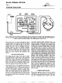
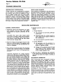
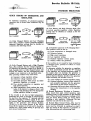
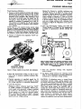
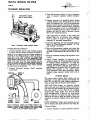
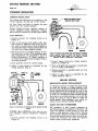
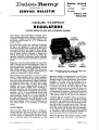
emy
1
ANDERSON. INDIANA. U.S.A.
blMetimn I P - l l 6 A
Date
8- 1-60
Page 1
10 Pages
SERVICE BULLETIN
File Under:
R-RELAYS AND
REGULATORS
STANDARD WATERPROOF
REGULATORS
(VOLTAGE REGULATOR UNITS WITH ACCELERATOR WINDING)
This -bulletin covers Delco-Remy standard threeunit waterproof generator regulators containing an
accelerator winding on the voltage regulator unit
and having a suffix letter "B" or "C" following the
model number.
The Delco-Remy three unit regulators illustrated
by Fig. 1 are designed for use with generators
which have the field circuit insulated in the generator and grounded in the regulator. These regulators differ from those discussed in Bulletin 1R-116
only in design features. Changes in design have
altered the routing of the field circuit within the
regulator. Methods of adjustment remain basically
the same for the regulators described in both bulletins.
Regulators covered in this bulletin are most often
used on aircraft and 24-volt applications. They include an accelerator or series winding on the voltage regulator unit. Adjusting procedures for this
type voltage regulator unit differ from those procedures used on voltage regulator units that do not
contain an accelerator or series winding.
The regulator shown in Figure 1consists of a cutout
relay, a voltage regulator, and a current regulator
unit. The cutout relay closes the generator-to-battery circuit when the generator voltage is sufficient
to charge the battery, and it opens the circuit when
the generator slows down or stops. The voltage
regulator unit is a voltage-limiting device that
prevents the system voltage from exceeding a
specified maximum and thus protects the battery
and other voltage-sensitive equipment. The current
regulator unit is a current-limiting device that
limits the generator output so as not to exceed its
rated maximum. Figure 2 is a wiring diagram of
this type regulator when the vehicle frame is the
ground return. Figure 3 is a wiring diagram of this
same type regulator when a wire is the ground return which makes it an insulated or two-wire
system.
CUTOUT RELAY
The cutout relay (Figs. 2 & 3) has two windings, a
series winding of a few turns of heavy wire (shown
in solid red) and a shunt winding of many turns of
fine wire (shown in dashed red). The shunt winding is connected across the generator so that
CO: 1.2. 1 W D S b P S . 1.2X. 131. 132: 16. 1FD
TERMINAL
Figure
TERMINAL
TERMINAL
1-Delm-Remy three-unit current and voltage regulator with the cover removed.
generator voltage is impressed upon it at all times.
The series winding is connected in series with the
charging circuit so that all generator output passes
through it. The relay core and windings are assembled into a frame. A flat steel armature is attached to the frame by a flexible hinge so that it
is centered just above the end of the core. The
armature contact points are located just above the
stationary contact points. When the generator is
not operating, the armature contact points are held
awax from the stationary points by the tension of
a flat spring riveted on the side of the armature.
CUTOUT RELAY ACTION-When the generator
voltage builds up a value great enough to charge
the battery, the magnetism induced by the relay
windings is sufficient to pull the armature toward
the core so that the contact points close. This completes the circuit between the generator and battery. The current which flows from the generator
to the battery passes through the series winding
in a direction to add to the magnetism holding the
armature down and the contact points closed.
When the' generator slows down or stops, current
begins to flow from the battery to the generator.
PRINTED I N U.S.A.
Service BwiBe#iao 1P-116A
Page 2
STANDARD REGULATORS
BATTERY
CUTOUT
REUY
CURRENT
REGUUTOR
VOLTAGE
REGULATOR
AMMETER
Figure 2-Wiring circuit of Deleo-Remy grounded type, three-unit regulator shown in Figure 1. The shunt windings in the cutout relay and voltage regulator are shown in dashed rrd, The series windings in the cutout relay and current regulator are
shown in solid nd. The series winding i n the voltage regulator h shown in blue.
This reverse flow of current through the series
winding causes a reversal of the series winding
magnetic field. The magnetic field of the shunt
winding does not reverse. Therefore, instead of
helping each other, the two windings now magnetically oppose so that the resultant magnetic
field becomes insufficient to hold the armature
down. The flat spring pulls the armature away
from the core so that the points separate; this
opens the circuit between the generator and
battery.
VOLTAGE REGULATOR
The voltage regulator (Figs. 2 & 3) has two windings assembled on a single core, a shunt winding
consisting of many turns of fine wire (shown in
dashed red) which is shunted across the generator,
and a series winding of a few turns of relatively
heavy wire (shown in solid blue) which is connected in series with the generator field circuit
when the regulator contact points are closed.
The windings and core are assembled into a frame.
A flat steel armature is attached to the frame by
a flexible hinge so that it is just above the end of
the core. The armature contains a contact point
which is just beneath a stationary contact point.
When the voltage regulator is not operating, the
tension of a spiral spring holds the armature away
from the core so that the points are in contact and
the generator field circuit is completed to ground
through them.
VOLTAGE REGULATOR ACTION-When
the
generator voltage reaches the value for which the
voltage regulator is adjusted, the magnetic field
produced by the two windings (shunt and series)
overcomes the armature spring tension and pulls
the armature down so that the contact points
separate. This inserts resistance into the generator
field circuit so that the generator field current and
voltage are reduced. Reduction of the generator
voltage reduces the magnetic field of the regulator
shunt winding. Also, opening the regulator points
opens the regulator series winding circuit so that its
magnetic field collapses completely. The consequence is that the magnetic field is reduced sufficiently to allow the spiral spring to pull the armature away from the core so that the contact
points again close. This directly grounds the generator field circuit so that generator voltage and output increase. The above cycle of action again takes
place and the cycle continues at a rate of 50 to 200
times a second, regulating the voltage to a predetermined value. With the voltage thus limited the
generator supplies varying amounts of current to
meet the varying states of battery charge and
electrical load.
CURRENT REGULATOR
The current regulator (Figs. 2 & 3) has a series
winding of a few turns of 'heavy wire (shown in
red) which carries all generator output. The winding core is assembled into a frame. A flat steel
Page 3
I
STANDARD REGULATORS
F'iguxe'3--W*
Circuit d I)elco-lknv inwkted type, t h r e e - 4 regulator d m i h to that shown in Figme 1. The shunt
windings in tbe cutout d a y and vdbge r e g d a k are shown In dahcd red, Tbc series windings in the cutout relay and cur.
rent regalator are shown in d i d red. Tbs aeries w h h g in tbe voltage regulator is shown in blue.
armature is attached to the frame by a flexible
hinge so that it is just above the core. The armature has a contact point which is just below a stationary contact point. When the current regulator
is not operating, the t a d o n of a spiral spring holds
the m a t u r e away from the core so that the points
are in contact. In this position the generator field
circuit is completed to ground through the current
regulator contact points in series with the voltage
regulator contact points.
CURRENT REGULATOR ACTION-When
the
load demands are heavy, as for example, when
electrical devices are turned on and the battery is
in a discharged condition, the voltage may not
increase to a value sufficient to cause the voltage
regulator to operate. Consequently, generator output will continue to increase until the generator
reaches rated maximum current. This is the current
value for which the current regulator is set. Therefore, when the generator reaches rated output, this
output, flowing through the current regulator
winding, creates sufficient magnetism to pull the
current regulator armature down and open the
contact points. With the points open, resktance is
inserted into the generator field circuit so that the
generator output is reduced.
As soon as the generator output starts to fall off,
the magnetic field of the current regulator winding
is reduced, the spiral spring tension pulls the armature up, the contact points close and directly connect the generator field to ground. Output increases
and the above cycle is repeated. The cycle continues to take place while the current regulator is
in operation 50 to 200 times a second, preventing
the generator from exceeding its rated maximum.
When the electrical load is reduced (electrical devices turned off or battery comes up to charge),
then the voltage increases so that the voltage regulator begins to operate and tapers the generator
output down. This prevents the current regulator
from operating. Either the voltage regulator or the
current regulator operates at any one time-the
two do not operate at the same time.
RESISTANCES
The current and voltage regulator circuits use a
common resistor (Figs. 2 & 3) which is inserted in
the field circuit when either the current or voltage
regulator operates. A second resistor* (Figs. 2 & 3)
is connected between the regulator field terminal
and the cutout relay frame, which places it in
parallel with the generator field coils. The sudden
reduction in field current occurring when either
the current or voltage regulator contact points
open, is accompanied by a surge of induced voltage in the field coils as the strength of the magnetic field changes. These surges are partially dissipated by the two rbsistors, thus preventing excessive arcing at the contact points.
*NOTE: The second resistor is not present on all
regulators. Many Aircraft regulators have this resistor omitted.
Page 4
STANDARD REGULATORS
TEMPERATURE COMPENSATION
Voltage regulators are compensated for temperature by means of a bimetal thermostatic hinge on
the armature. This causes the regulator to regulate at a higher voltage when cold which partly
compensates for the fact that a higher voltage is
required to charge a cold battery. Many current
regulators also have a bimetal thermostatic hinge
on the armature. This permits a somewhat higher
generator output when the unit is cold, but causes
the output to drop off as temperature increases.
REGULATOR POLARITY
Some regulators are designed for use with negative
grounded systems, while other regulators are designed for use with positive grounded systems.
Using the wrong polarity regulator on an installation will cause the regulator contact points to pit
badly and give short life. As a safeguard against
installation of the wrong polarity regulator, all
regulators of this type have the model number and
the polarity clearly stamped on the end of the
regulator base.
REG'ULATOR MAINTENANCE
GENERAL INSTRUCTIONS
1. Mechanical checks and adjustments (air gaps,
point opening) must be made with battery
disconnected and regulator preferably off the
vehicle.
CAUTION: The cutout relay contact points
must never be closed by hand with the battery
connected to the regulator. This would cause a
high current to flow through the units which
would seriously damage them.
2. Electrical checks and adjustments may be made
either on or off the vehicle. The regulator must
always be operated with the type generator for
which it is designed.
3. The regulator must be mounted in the operating
position when electrical settings are checked
and adjusted and it must be at operating temperatwe.*
*Operating temperature for voltage regulator
checking and adjusting is reached after 15 minutes of continuous operation of the voltage regulator unit, with the regulator cover in place and
the proper resistor in series with the generator.
For proper resistance values, see the "Voltage
Setting" procedure under the "Regulator Checks
and Adjustments" section. It is not necessary to
measure the amount of current flowing during
. warm-up or testing of the voltage unit; however,
it is important that no electrical load other than
ignition be turned on during the test. (If a variable resistor is used in series with the battery,
set to 1-10 amperes for warm-up period.) Operating temperature for temperature-compensated
current regulators is reached after 15.minutes of
operation with current regulator operating and
cover in place. (Noncompensated current regulators operate the same, hot or cold. Operating
temperature, therefore, may be disregarded.)
4. Specified generator speeds for testing and adjusting.
a. Voltage Regulator
(1) For passenger cars and trucks, 3,500 generator r.p.m.
(2) Operating speed for constant speed engines (light aircraft engines included in
this classification).
(3) Governed speed for govenied engines.
b. Current Regulator
(1) All generators must be operated at a
speed sufficient to produce current in
excess of specified setting.
(2) Voltage of the generator must be kept
high enough to insure sufficient current
output, but below the operating voltage
of the voltage regulator unit.
5. After any tests or adjustments the generator
on the vehicle must be polarized after leads are
connected, but before the engine is started, as
follows:
POLARIZING GENERATOR
After reconnecting leads, momentarily connect a
jumper lead between the "GEN" and "BAT"
terminals of the regulator. This allows a momentary surge of current to flow through the generator
which correctly polarizes it. Failure to do this may
result in severe damage to the equipment since
reversed polarity causes vibration, arcing, and
burning of the relay contact points.
CAUTION: If a fuse is located on the regulator,
polarize the generator by momentarily placing a
jumper between the "GEN" terminal and the screw
on the fuse to which the lead is connected. If the
other screw on the fuse is touched, the fuse may
blow.
.
Page 5
STANDARD REGULATORS
QUICK CHECKS OF GENERATOR AND
REGULATOR
+a-
In analyzing complaints of generator-regulator
operation, any of several basic conditions may be
found.
HIGH
w
CHARGING RATE
NOR$AL
DISCHARGED
(3) Low Battery and High Charging Rate-This
tzQ-
is normal generator-regulator action Regulator
settings may be checked as outlined in the fol-
I
lowing section.
LOW
CHARGING RATE
NOF~GAL
#b
FULLY CHARGED
(1) Fully Charged Battery and Low Charging
Rate-This indicates normal generator-regulator
operation. Regulator settings may be checked as
outlined in the following section.
+ --
I
I
HlGH
CHARGING RATE
FULLY CHARGED
(2) Fully Charged Battery and a High Charging
Rate--%
indicates that the voltage regulator is
not reducing the generator output as it should. A
high charging rate to a fully charged battery will
damage the battery and the accompanying high
voltage is very injurious to all electrical units.
This operating condition may result from:
(a) Improper voltage regulator setting.
(b) Defective voltage regulator unit.
(c) Grounded generator field circuit (in either
generator, regulator or wiring).
(d) Poor ground connection at regulator and
high speed operation.
(e) High temperature which reduces the resistance of the battery to charge so that it will
accept a high charging rate even though the
voltage regulator setting is normal.
If the trouble is not due to high temperature,
determine the cause of trouble by disconnecting
the lead from the regulator "F" terminal with the
generator operating at medium speed. If the output remains high, the generator field is grounded
either in the generator (see Service Bulletin
1G-150) or in the wiring harness. If the output
drops off the regulator is at fault and it should be
checked for a high voltage setting or grounds and
poor ground connections.
I
DISCHARGED
-
LOW OR NO
CHARGING RATE
UNDERCHARGING
w
w
(4) Low Battery and Low or No Charging Rate-This condition could be due to:
(a) Loose connections or damaged wires.
(b) Defective battery.
(c) High circuit resistance.
(d) Low regulator setting.
(e) Oxidized regulator contact points.
(f) Defects within the generator.
If the condition is not caused by loose connections
or damaged wires, proceed as follows to locate
cause of trouble.
To determine whether the generator or regulator
is at fault, momentarily ground the "F" terminal
of the regulator and increase generator speed. If
the output does not increase, the generator is
probably at fault and it should be checked as outlined in Service Bulletin 1G-150. If the generator
output increases, the trouble is due to:
(a) A low voltage (or current) regulator setting.
(b) Oxidized regulator contact points which insert excessive resistance into the generator
field circuit so that output remains low.
(c) Generator field circuit open within the regulator at the connections or in the regulator
winding.
(5) Burned Resistances, Windings or ContactsThese result from open circuit operation, open
resistance units, or high resistance in the charging
circuit. Where burned resistances, windings or contacts are found, always check car wiring before
installing a new regulator. Otherwise, the new
regulator may also fail in the same way.
(6) Burned Relay Contact Points-This may be
due to reversed generator polarity. Generator polarity must be corrected as explained on page 4
after any checks of the regulator or generator, or
after disconnecting and reconnecting leads.
Page 6
STANDARD REGULATORS
CLEANING CONTACT POINTS
The contact points of a regulator will not operate
indefinitely without same attention It has been
found that a great majority of all regulator trouble
can be eliminated by a simple cleaning of the contact points, plus some possible readjustment. The
flat points should be cleaned with a spoon or m e r
file. On negative grounded regulators which have
the flat contact point on the regulator armatures,
loosen the contact bracket mounting screws so that
the bracket can be tilted to one side (Fig. 5). On
positive grounded regulators, the flat point is in the
upper contact bracket so the bracket must be removed for cleaning the points. A flat file cannot be
used successfully to clean the flat contact points
since it will not touch the center of the flat point
where point wear is most apt to occur. NEVER
USE EMERY CLOTH OR SANDPAPEZt TO
CLEAN THE CONTACT POINTS. Remove all
the oxides from the contact points but note that
it is not necessary to remove &y cavity that may
have developed.
S P O O N OR RJFFLER
FILE
\
-
--ry
..
TO CLEAN CONTACT POINTS
(LOOSEN UPPER CONTACT
BRACKET MOUNTING SCREWS)
ADAPTING VOLTAGE REGULATOR
SETIWG FOR UNUSUAL CONDITIONS
m m
The voltage regulator setting at times may need to
be "tailored" to adapt it to the battery and type of
service. The ideal setting is that which will keep
the battery at or near full charge with minimum
use of water. The "normal" setting (value shown
in test specifications) usually will be satisfactory
for average service. However, if service is above
or below average, the setting must be tailored to
fit the job. Either of two conditions which may
exist will require tailoring: (1) battery is being
overcharged (using too much water), (2) battery
remains undercharged (3A charge or less). Corrections may be made as follows:
(1) If battery uses too much water at normal setting, reduce voltage setting 0.1 or 0.2 of a volt
and check for improved condition over a reasonable service.period. Repeat until battery remains charged with a minimum use of water.
It rarely will be necessary to go below 13.8
volts on a 12-volt system or 6.9 volts on a &volt
system or 27.6 volts on a 24-volt system.
CAUTION: Whenever the voltage setting is reduced, the cutout relay must also be checked and
reduced if necessary. It must be at least 0.5 of a
volt less than voltage regulator setting.
(2) If battery is consistently undercharged at
normal setting, increase the voltage setting
0.1 of a volt and check for improved condition
over a reasonable service period. Repeat until
the battery remains charged with a minimum
use of water. It rarely will be necessary to increase the voltage above 14.8 on a 12-volt system or 7.5 volts on a &volt system or 29.6 volts
on a 24-volt system.
CAUTION: When increasing voltage avoid settings
high enough to damage lights or other voltagesensitive equipment during cold weather operation.
Before tailoring the voltage setting for unusual
c o n d i t k m be sure the battery is normal-not
sulfated, not permanently damaged due to having
been overheated, not operating in too hot a location, and not poorly ventilated.
&Ulw&ating use of spoon or rimer file to clean flat
eontact points in regulator.
REGULATOR CHECKS AND
ADJUSTMENTS
(See Delco-Remy Service Bulletins lR-180, lR185, or 1R-186 for Specifications.)
Procedure: For best results, the following steps
should be taken in the sequence given:
(1) Bring voltage regulator to operating temperature, (2) Check voltage regulator, (3) Check
cutout relay. (4) Bring current regulator to
operating temperature, (5) Check current regulator.
VOLTAGE REGULATOR
Two checks and adjustments are required on the
voltage regulator, air gap and voltage setting.
Air G a p t o check air gap, push armature down
until the contact points are just touching and then
measure air gap (Fig. 5). Adjust by loosening the
contact mounting screws and raising or lowering
contact bracket as required. Be sure the points
are lined up and tighten screws after adjustment.
Voltage Setting-There are two ways to check the
voltage setting-the heed resistance method and
the variable resistance method (Figs. 6 and 8).
::
j~
Page 7
STANDARD REGULATORS
Fixed Resistance Method1. Connect a fixed resistance between the battery
terminal and ground as shown in Fig. 6 after
disconnecting the battery lead from the battery
terminal of the regulator. The resistance must
be 3/4 ohm* for &volt units, 1%ohms* for 12
volt units, 7 ohms for 24volt units. It must be
capable of carrying 10 amperes for 6- and 12
volt systems, 6 7 amperes for 24-volt systems,
without any change of resistance with temperature changes.
*NOTE:With all 6-volt regulators having current ratings
less than 15 amperes, it is necwary to use a 1%ohm h e d
resistance to avoid interference from the current regulator.
With all 12-volt regulators having current ratings less than
15 amperes, a 2%-ohm fixed resistance (%-ohm and 1%ohm resistors in series) must be used for the same reason.
2. Connect a voltmeter from regulator "BAT' terminal to ground.
Method ELConnect a variable resistance into
the field circuit, as in Figure 6. Turn out all
resistance. Operate generator at specified speed.
Slowly increase (turn in) resistance until generator voltage is reduced to 2 volts on a &volt
system, 4 volts on a 12-volt system or 6 volts on
a 24-volt system. Turn out all resistance again,
and note voltage setting (with voltmeter connected as in Figure 6). Regulator cover must be
in place.
6. Note the thermometer reading and select the
Normal Range of Voltage for this temperature
as W in specifications 1R-180, 1R-185, 1R186.
AIR GAP
(CHECK WITH POINTS
-2 OHM-12 VOLT
OHM--24 VOLT
Figure &Fixed resistance and voltmeter connections to check
voltage regulator setting by fixed resistance method. F'ixed
resistance leads shown in red and voltmeter lea& shown in
blue. Variable resistance may be connected as shown for
cycling generator.
MOUNTING SCREWS
(LOOSEN T O SET AIR GAP)
~ y r 5--Voltage
e
regulator air
Z~P
check and 4-t
7. Note the voltmeter reading with regulator
cover in place.
3. Place the thermometer within % inch of regulator cover to measure regulator ambient temperature.
8. To adjust voltage setting turn adjusting screw
(Fig. 7). Turn clockwise to increase setting and
counterwise to decrease voltage setting.
4. Operate generator at specified speed for 15
minutes with regulator cover in place to bring
the voltage regulator to operating temperature.
CAUTION: If adjusting screw is turned down
(clockwise) beyond range, spring support may
not return when screw is backed off. In such case,
turn screw counterclockwise until there is ample
clearance between screw head and spring support.
Then bend spring support up carefully until it
touches the screw head. Final setting of the unit
.should always be made by increasing spring tension, never by reducing it. If setting is too high
adjust unit below required value and then raise to
exact setting by increasing the spring tension.
After each adjustment and before taking reading
replace the regulator cover and cycle the generator.
5. Cycle the generator:
Method A-Move voltmeter lead from "BAT"
to "GEN" terminal of regulator. Retard generator speed until generator voltage is reduced
to 2 volts on a &volt system, or 4 volts on a
12-volt system or 6 volts on a 24volt system,
Move voltmeter lead back to "BAT" terminal
of regulator. Bring generator back to specified
speed, and note voltage setting.
Se~lriceBaa%ie.fba1P-136A
Page 8
STANDARD REGULATORS
*-.
&)
2 V,
ADJUSTING SCREW
(TURN TO ADJUST SETTING)
3. Place thermometer within 4/4 inch of regulator
cover to measure regulator ambient tempera-
ture.
4. Operate generator at spe&ed speed. Adjust
variable resistor until current flow is 8-10 amperes ( 4 6 amperes on 6- and 12-volt generators
having current ratings of less than 15 amperes).
If less current than is required above is flowing
it will be necessary to turn on vehicle lights to
permit increased generator output. Variable resistance can then be used to decrease current
flow to the required amount.
Allow generator to operate at this speed and
current flow for 15 minutes with regulator
cover in place in order to bring the voltage
. regulator to operating temperature.
Figure 7-Adjusting
voltam ryPLQr actthy.
Variable Resistance Method1. Connect ammeter and % ohm variable resistor
in series with the battery a s shown in Figure 8.
NOTE-It is very important that the variable resistance be
connected at the "BAT" terminal as shown in Figure 6
rather than at the "GEN" termid, even though these
terminals are in the same circuit. An examination of the
wiring diagram, Figures 2 and 3, will show that -tion
begins at the point where the shunt winare connected to the series circuit. Any small resktance added to
the circuit between the generator and this point will simply
be offset by a rise in generator voltage without atlectiug
the output shown at the ammeter.
2. Connect Voltmetej between "BAT' tenninal
and ground.
:
5. Cycle the generator by either method listed in
Step 5 of "Fixed Resistance Method" of "Voltage Setting" procedure.
6. Note the thermometer reading and select the
" N o d Range" of voltage for this temperature
as listed in specitications lR-180, lR-185, or 1R186.
7. Note the voltmeter reading with regulator cover
in place.
8. Adjust voltage regulator as reguired as described in Step 8 of "Fixed Resistance Method"
of "Voltage Setting Procedure." In using the
variable resistance method, it is necessary to
readjust the variable resistance after each voltage adjustment to assure that 8-10 amperes are
flowing (4-6 amperes on low output units).
Cycle generator after each adjustment before
reading voltage regulator setting with cover in
place.
CUTOUT RELAY
The cutout relay requires three checks and ad-.
justments: air gap, point opening, and closing voltage. The air gap and point opening adjustments
must be made with the battery disconnected.
AIR GAP-Place
fingers on armature directly
above core and move armature down until points
just close and then measure air gap between armature and center of core (Fig. 9). On multiple
contact point relays, make sure that all points
close simultaneously. If they do not, bend spring
h g e r so they do. To adjust air gap, loosen two
screws at the back of relay and raise or lower the
armature as required. Tighten screws after adjustment.
POINT OPENING-Check point opening and adammeter and variable redstance eonneetiom for checking voltage ngalptor seUiug by the variable
redstance method. Variable nsishnce and ammeter leads
shown in red and voltmeter h d s in blue
Figure &Voltmeter,
just by bending the upper armature stop (Fig. 10).
Closing Voltage-1. Connect regulator to proper generator a d bat-
Service Bulletin 1W-116A
Page 9
STANDARD REGULATORS
tery. Connect voltmeter between the regulator
"GEN" terminal and ground. (Fig. 11).
VARIABLE RESISTANCE
2. Method A--Slowly increase generator speed
and note relay closing voltage. Decrease generator speed and make sure the cutout relay
points open.
Figure 11-Voltmeter conneetiom to cheek cutout relay dosh g voltage.. Variable resistance may be connected as shown
for cycling generator.
ADJUSTING SCREWS
(LOOSEN TO SET AIR GAP)
~igure
W u t o u t relay air gap check and a d M m = t
Battul
must be disconnected whm this check is made.
Method B-Make connections as in Step 1,but
in addition add a variable resistor connected
If
UPPER ARMATURE STOP
(BEND 10 ADJUST
POINT OPENING)
Figure IO-Cutout relay point opening check and adjustment.
Battery must be disconnected when this check is made
into the field circuit (Fig. 11).Use a 15 ohm-25
watt resistor for 6-volt systems, or 25 ohm-25
watt resistor for 12- and 24-volt systems. Operate generator at medium speed with variable
resistance turned all in. Slowly decrease (turn
out) the resistance until cutout relay points
close. Note closing voltage. With cover in place
slowly increase (turn in) resistance to make
sure points open.
3. Adjust closing voltage (either method) by turning adjusting screw (Fig. 12). Turn screw
clockwise to increase setting and counterclockwise to decrease setting.
Figure 12-Adjustment
of cutout relay closing voltage.
Service BuBSetim 1P-dl6A
Page 10
STANDARD REGULATORS
-
--
CURRENT REGULATOR
Two checks and adjustments are required on the
current regulator: ai-r gap and current setting.
R I W T m
-
JUMPER LEAD BRIDGING VOLTAGE
REGULATOR CONTACT POINTS
Air Gap-Check and adjust in exactly the same
manner as for the voltage regulator.
Current Setting-Current
regulator setting on
current regulators having temperature compensation should be checked by the following method:
LOAD METHOD1. Connect ammeter into charging circuit, as in
Figure 13.
2. Turn on all accessory load (lights, radio, .etc.)
and connect an additional load across the battery (such as a carbon pile or bank of lights) so
as to drop the system voltage approximately one
volt below the voltage regulator setting.
3. Operate generator at specified speed for 15 minutes with cover in pLace. (This establishes operating temperature; see paragraphs 3 and 4 in
General Instructions.) If current regulator is
not temperature-compensated, disregard 15-minute warm-up period.
AMMmR
GENERATOR
Figure 1CAmmeter and jumper lead connections for checking
cumnt regulator setting by jumper lead method. Ammeter
leads and jumper leads shown in red. (Only for current
regulators without temperature compensation)
4. Cycle generator and note current setting.
2. Connect jumper lead across voltage regulator
points, as in Figure 14.
5. Adjust in same manner as described for the
voltage regulator (Fig. 7).
3. Turn on all lights and accessories or load battery
as in "2" under Load Method.
4. Operate generator at specified speed and note
current setting.
5. Adjust in same manner as described for the
voltage regulator (Fig. 7).
REPAIR SECTION
REGULATOR SPRING REPLACEMENT
If it becames necessary to replace the spiral spring
on either the current or voltage regulator unit,
the new spring should first be hooked on the lower
spring support and then stretched up until it can
be hooked at the upper end. Stretch the spring only
by means of a screwdriver blade inserted between
the turns (or in a similar manner)--do not pry the
spring into place, as this is likely to bend the
spring support. After installing a new spring, readjust the unit setting as already described.
RADIO BY-PASS CONDENSERS
Figure 13--Connections for checking cumnt regulator by load
method.
JUMPER LEAD METHOD-(Use only for current regulators without temperature compensation.)
1. Connect ammeter into charging circuit, as in
Figure 14.
The installation of radio by-pass condensers on
the field terminal of the regulator or generator will
cause the regulator contact points to burn and
oxidize so that generator output will be reduced
and a rundown battery will result. If a condenser
is found connected to either of these terminals, disconnect the condenser and clean the regulator
contact points as previously explained.