1
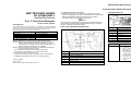
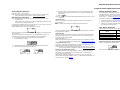
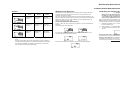
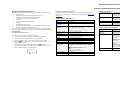
GasAlertClip Extreme English Instruction Sheet
D2139/7 Page 1
Trimmed and folded dimensions: 4.125 (w) x 5.875 (h)
BW TECHNOLOGIES
BY HONEYWELL
GasAlertClip Extreme
2 or 3 Year Gas Detector
Instruction Sheet
Introduction
The GasAlertClip Extreme gas detector (“the detector”) is a personal safety
device that warns when hazardous gas exceeds factory set alarm setpoints.
The detector stores and transmits gas alarm event data. It is your
responsibility to respond properly to the alarms.
Gas Detected
Oxygen (O2)
Carbon monoxide (CO)
Hydrogen sulfide (H2S)
Sulfur dioxide (SO2)
a Safety Information - Read First
ec Note:
This instrument contains a lithium battery. Do not mix with the solid
waste stream. Spent batteries should be disposed of by a qualified
recycler or hazardous materials handler.
Parts of the GasAlertClip Extreme
Unit of Measure
Percent by volume (%)
Parts per million (ppm)
Parts per million (ppm)
Parts per million (ppm)
a Safety Information - Read First
Warning: Substitution of components may impair Intrinsic Safety.
Warning: Bump test the O2 detector before each day’s use to confirm its
ability to respond to gas by exposing the detector to a gas
concentration that exceeds the alarm setpoints. Manually verify
that the audible and visual alarms are activated.
Warning: To prevent ignition of flammable or combustible atmospheres,
disconnect power before servicing.
⇒ Do not activate the detector after the date on the package.
⇒ This product is a gas detector, not a measurement device.
⇒ Perform a self-test each day prior to use.
⇒ Ensure the sensor grill is free of dirt, debris, and is not obstructed.
⇒ Calibrate and bump test the detector in an ordinary location.
D2139/7 [English]
iERP: 124661
© BW Technologies 2006, all rights reserved.
Display Elements
⇒ Periodically test the response of the sensor to gas by exposing the
detector to a target gas concentration that exceeds the low alarm setpoint.
Manually verify that the audible and visual alarms are activated.
⇒ Periodically calibrate the GasAlertClip Extreme O2.
1
Self-test status
2
High and low alarm setpoints
3
Data transmission
4
Maximum exposure in alarm
5
Gas type
2/6
Alarm condition
7/8
Detector life-remaining indicators
4/8
Months/hours/days since last maximum exposure
Pushbutton
Pushbutton
Description
•
•
1
Audible alarm
2
Visual alarm
3
Infrared download port
4
Liquid crystal display (LCD)
5
Alligator clip
6
Start/test button
7
Sensor and sensor grill
•
C
•
•
•
To activate the detector, press and hold C for
5 seconds.
Press C within 24 hours of a gas alarm to view
the maximum gas exposure.
When Test displays, press and hold C for
approximately 1 second to activate the self-test.
To calibrate the O2 detector, press and hold C
for approximately 3 seconds.
To display the gas alarm setpoints, press C.
To transmit the data, press C when Prn and
display.
GasAlertClip Extreme English Instruction Sheet
D2139/7 Page 2
Trimmed and folded dimensions: 4.125 (w) x 5.875 (h)
Activating the Detector
Press and hold C for 5 seconds.
Note: Once activated the detector cannot be deactivated, except after a
battery life-ending alarm. Refer to Safety Shutdown Mode.
5. If an alarm has occurred in the last 24 hours, the LCD displays the
maximum gas exposure value and the hours that have lapsed since
the exposure.
6. Prn and
flash.
Performing a Self Test
Note: If a self-test is activated without Test being displayed, steps #1-3 are
bypassed.
Note: The self-test must be performed in an atmosphere that is free of
hazardous gas.
Self-Test Pass
After a self-test is performed, wait 30 seconds before using to ensure
the detector accurately detects gas.
The self-test is activated prior to any other function. Prior to each day’s use,
a self-test of the detector must be performed.
When the self-test is successful, the detector emits a short beep and a
single vibration.
u then displays to verify that the detector passed the self-test.
When Test displays on the LCD, a self-test is required.
Safety Shutdown Mode
The LCD displays a blank screen when initiating safety shutdown mode.
The detector beeps, flashes, and vibrates rapidly (twice per second) until
the battery loses power. To deactivate the detector before the battery loses
power, press C. Contact BW Technologies by Honeywell.
The detector initiates safety shutdown mode if the
•
self-test fails three consecutive times,
•
automatic battery test fails five consecutive times, or
•
detector has not been manually deactivated within 8 hours of initiating
the detector life-ending alarm.
Gas Alarm Setpoints
The following is a list of the factory alarm setpoints.
When the self-test is performed and passes, u displays to confirm the tests
are successful.
Twenty hours after performing the self-test, Test displays again to indicate
that a self-test is required.
Model
Low Alarm
Setpoint
High Alarm
Setpoint
Self-Test Fail
GasAlertClip Extreme O2
19.5%
23.5%
GasAlertClip Extreme CO
35 ppm
200 ppm
1. The detector emits one beep, one flash, and one vibration.
If the self-test fails, the detector emits five short beeps and flashes before
displaying a blank screen. The LCD then returns to the normal operating
screen and again displays Test.
GasAlertClip Extreme H2S
10 ppm
15 ppm
2. All LCD elements display.
Repeat the self-test.
GasAlertClip Extreme SO2
5 ppm
10 ppm
To perform a self-test, press and hold C for approximately 1 second. to
initiate the self-test. Confirm that the following tests are performed:
3. Test flashes while the sensor integrity and battery life are tested.
4. The low and high alarm setpoints display.
Note: If the self-test fails three consecutive times, the LCD displays a blank
screen and the detector deactivates. Refer to Safety Shutdown Mode.
Note: Detector may be configured with customer specified alarm setpoints.
Automatic Battery Test
Press C to display the alarm setpoints.
Displaying the Gas Alarm Setpoints
The battery is automatically tested every 2 hours. If the battery test fails,
another automatic test is initiated 30 minutes later.
Note: After five consecutive battery test failures, the LCD displays a blank
screen and the detector deactivates. Refer to Safety Shutdown Mode.
Detector Life-Remaining Clock
The detector life-remaining clock indicates how much longer the detector
will operate. The LCD displays the countdown value of the remaining
months, days, and then hours.
The detector continues to operate for a maximum of 8 hours after the
detector life-ending alarm initiates. Press C to deactivate the detector. For
more information, refer to Alarms.
Alarm setpoints are factory configured and cannot be modified.
GasAlertClip Extreme English Instruction Sheet
D2139/7 Page 3
Trimmed and folded dimensions: 4.125 (w) x 5.875 (h)
Maximum Gas Exposure
Alarms
Display
Low Gas Alarm
High Gas Alarm
Audible
Alarm
One slow
beep every
second
Two fast
beeps every
second
Visual
Alarm
One slow
flash every
second
Two fast
flashes every
second
Vibration
Alarm
One slow
vibration
every second
Two fast
vibrations
every second
The detector records the maximum gas exposure that triggers an alarm
condition and begins calculating the number of hours from when the
maximum exposure occurred.
Calibrating the Oxygen (O2) Detector
a Warning
Bump test the O2 detector before each day’s use, to confirm
its ability to respond to gas by exposing the detector to a gas
concentration that exceeds the alarm setpoints. Manually
verify that the audible and visual alarms are activated.
For each new exposure greater than the current maximum exposure, the
detector resets the maximum gas exposure to the new level and resets the
hours to 0. After 24 hours of gas readings in the acceptable range, the
detector resets both values to 0.
Every 30 days when the O2 detector is due for calibration, the LCD flashes
CAL and the detector life-remaining value to indicate that calibration is due.
Viewing the Maximum Gas Exposure
To calibrate the O2 detector, complete the following:
Press C within 24 hours of receiving a gas alarm. The LCD displays the
following:
The low and high alarm setpoints.
1. Calibrate the detector only in a normal atmosphere (20.9% O2) that is
free of hazardous gas.
2. Press and hold C for approximately 3 seconds.
3. The detector emits one beep, one flash, and displays the following
screen:
Life-Ending Alarm
Eight slow
beeps per
minute
Eight slow
flashes per
minute
Eight slow
vibrations
per minute
If a maximum gas exposure has occurred within the last 24 hours, the
maximum gas exposure screens display.
Unsuccessful Calibration: If the detector does not beep or vibrate after a
calibration, repeat steps 1 and 2 again. If the second attempt is
unsuccessful, contact BW Technologies by Honeywell.
Note: When the gas level returns to the acceptable range, the gas alarm
stops.
The life of the battery decreases rapidly when in alarm conditions.
The battery life-ending alarm occurs when the battery life-remaining
clock displays 0 hours. The detector will continue to operate for
8 hours before automatically deactivating.
Successful Calibration: The detector emits one vibration and one
extended beep to indicate that calibration is successful.
For exposures beyond the detection range, over limit (OL) displays.
GasAlertClip Extreme English Instruction Sheet
D2139/7 Page 4
Trimmed and folded dimensions: 4.125 (w) x 5.875 (h)
Gas Event Data Transmission
Transferring Data to a Printer
The detector stores the last ten alarm events. The recorded data includes the
To transfer data using the handheld IR printer, complete the following:
•
serial number,
•
detector life-remaining value (months/days/hours),
•
number of self-tests that have been performed,
•
total number of events that have occurred,
•
event type,
•
duration of all events encountered,
•
gas type,
•
alarm level(s) (ppm or %),
•
time elapsed since the alarm occurred (days/hours/minutes), and
•
duration of the alarm (minutes/seconds).
Using the handheld IR printer, complete steps 2-5 as listed for Transferring
Data to a PC.
Shelf life
1 year before activation
Weight
76 g (2.7 oz.)
Instrument
dimensions
28 x 50 x 81 mm (1.1 x 2.0 x 3.2 in.)
Operating
temperature
H2S:
CO:
SO2:
O2:
3. From the detector, press C to access the transmission screen.
flash on the detector LCD. Within 5 seconds, press C to
4. Prn and
begin the transmission.
5. While data is being transmitted, Y displays and
flashes. A
countdown timer displays as a percentage value (70%) and indicates
how much data remains to be transmitted.
36 Month detector: 3 years after activation,
assuming 1.5 minutes of alarm time/day
Detection range
H2S:
CO:
O2:
SO2:
0 to 100 ppm
0 to 300 ppm
0 to 30% by volume
0 to 100 ppm
Alarm setpoints
Instant low and instant high
Calibration
H2S, CO, SO2: Not required
O2: Self-calibrating
Note: This product has been classified for use in atmospheres not more
than 21% v/v O2.
Event Logging Specifications
Number of stored
events
Up to ten events encountered. If more than ten, the
older events are replaced by the newer events.
Operating humidity
5% to 95% relative humidity
(non-condensing)
Data transmission
method
Via infrared port to thermal printer or via IR
DataLink to PC (for ordinary locations only)
Audible alarm
≈ 95 dB at 30 cm (1 ft.)
Visual alarm
Flashing, wide-angled alarm lens with quad red
LEDs plus alarm LCD readout
Information
transmitted
Display
Liquid crystal display (LCD)
Serial number
Life remaining
Self-tests performed
Total number and duration of all events
encountered
Sensor type
Electrochemical cells
Detection technique
Instantaneous alarm
Battery
Lithium, non-replaceable
Ratings and
certifications
Classified by UL to both U.S. and Canadian
Standards as intrinsically safe for Class I, Division
1, Group A, B, C, D and Class I, Zone 0, Group IIC
1. Connect the IR DataLink to the PC. Activate the IR DataLink
2. Position the detector and the device 2 in. (5 cm) apart.
-40 to +50°C / -40 to +122°F
-30 to +50°C / -22 to +122°F
-30 to +50°C / -22 to +122°F
-20 to +50°C / -4 to +122°F
24 Month detector: 2 years after activation,
assuming 3-5 minutes of alarm time/day
Internal vibrating operates to: -15°C / +5°F
Transferring Data to a PC
To transfer the data to a PC, complete the following:
Maximum operating
life
General Specifications
Two options are provided to transmit the gas event data: 1) Transfer data to
a PC using an IR DataLink or 2) Print the data using the handheld IR printer.
Transfer Data
Safety Specifications
ATEX: CE 0539 g II 1 G EEx ia IIC T4
DEMKO 03 ATEX 0321968
IECEx
CE: European Conformity
ABS Type Approved VA-348-169-X
Ingress protection
IP 66/IP 67
EMI/RFI
Complies with EMC Directives 89/336/EEC
Last ten events:
Maximum exposure, MicroDock II bump check, or
O2 calibration
Data shown for maximum exposures and bump
checks:
Gas type and alarm level in ppm or %
Time elapsed since the alarm occurred in days,
hours, and minutes
Duration of alarm in minutes and seconds
Data transmission
time
45 seconds plus 10 seconds per record
GasAlertClip Extreme English Instruction Sheet
D2139/7 Page 5
Trimmed and folded dimensions: 4.125 (w) x 5.875 (h)
This equipment has been tested and found to comply with the limits for a
Class B digital device, pursuant to Part 15 of the FCC rules and ICES-003
Canadian EMI requirements. These limits are designed to provide
reasonable protection against harmful interference in a residential
installation. This equipment generates, uses and can radiate radio
frequency energy and, if not installed and used in accordance with the
instructions, may cause harmful interference to radio communications.
However, there is no guarantee that interference will not occur in a
particular installation. If this equipment does cause harmful interference to
radio or television reception, which can be determined by turning the
equipment off and on, the user is encouraged to try to correct the
interference by one or more of the following measures:
-- Reorient or relocate the receiving antenna.
-- Increase the separation between the equipment and the receiver.
-- Connect the equipment into an outlet on a circuit different from that to
which the receiver is connected.
-- Consult the dealer or an experienced radio/TV technician for help.
Contacting BW Technologies by Honeywell
To contact BW Technologies by Honeywell call:
USA: 1-888-749-8878
Canada: 1-800-663-4164
Europe: +44 (0) 1295 700300
Other countries: +1-403-248-9226
Warranty
LIMITED WARRANTY & LIMITATION OF LIABILITY
BW Technologies by
BW Technologies by
Honeywell
Honeywell
Honeywell
Corporate Headquarters
America
Europe
2840 - 2 Ave. SE
3279 West Pioneer Parkway
5 Canada Close
BW Technologies LP (BW) warrants this product to be free from defects in material and
workmanship under normal use and service for a period of two or three years
(depending upon detector), beginning on the date of activation. This Warranty is valid
only if the detector is activated by the date on the package. This warranty extends only
to the sale of new and unused products to the original buyer. BW’s warranty obligation
is limited, at BW’s option, to refund of the purchase price, repair, or replacement of a
defective product that is returned to a BW authorized service center within the warranty
period. In no event shall BW’s liability hereunder exceed the purchase price actually
paid by the buyer for the Product.
This warranty does not include:
a) fuses, disposable batteries or the routine replacement of parts due to the normal
wear and tear of the product arising from use;
b) any product which in BW’s opinion, has been misused, altered, neglected or
damaged by accident or abnormal conditions of operation, handling or use;
c) any damage or defects attributable to repair of the product by any person other
than an authorized dealer, or the installation of unapproved parts on the product;
or
The obligations set forth in this warranty are conditional on:
a) proper storage, installation, calibration, use, maintenance and compliance with
the product manual instructions and any other applicable recommendations of
BW;
b) the buyer promptly notifying BW of any defect and, if required, promptly making
the product available for correction. No goods shall be returned to BW until
receipt by the buyer of shipping instructions from BW; and
c) the right of BW to require that the buyer provide proof of purchase such as the
original invoice, bill of sale or packing slip to establish that the product is within
the warranty period.
Calgary, AB
Arlington, TX
Banbury, Oxfordshire
THE BUYER AGREES THAT THIS WARRANTY IS THE BUYER’S SOLE AND EXCLUSIVE
Canada T2A 7X9
USA 76013
United Kingdom OX16 2RT
REMEDY AND IS IN LIEU OF ALL OTHER WARRANTIES, EXPRESS OR IMPLIED,
Address correspondence to:
BW Technologies by Honeywell
nd
2840 – 2 Avenue S.E.
Calgary, AB
T2A 7X9
CANADA
Email us at: [email protected]
Visit BW Technologies by Honeywell’s web site at: www.gasmonitors.com
BW Technologies by
INCLUDING BUT NOT LIMITED TO ANY IMPLIED WARRANTY OF MERCHANTABILITY
OR FITNESS FOR A PARTICULAR PURPOSE. BW SHALL NOT BE LIABLE FOR ANY
SPECIAL, INDIRECT, INCIDENTAL OR CONSEQUENTIAL DAMAGES OR LOSSES,
INCLUDING LOSS OF DATA, WHETHER ARISING FROM BREACH OF WARRANTY OR
BASED ON CONTRACT, TORT OR RELIANCE OR ANY OTHER THEORY.
Since some countries or states do not allow limitation of the term of an implied
warranty, or exclusion or limitation of incidental or consequential damages, the
limitations and exclusions of this warranty may not apply to every buyer. If any
provision of this warranty is held invalid or unenforceable by a court of competent
jurisdiction, such holding will not affect the validity or enforceability of any other
provision.
![121290 CR-4000 Controller User Manual [English].pub](http://vs1.manualzilla.com/store/data/005770288_1-ff1b31ed544f6d88740c7f5db9da46b2-150x150.png)