1
Visual Building Solar Designer User Manual
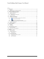
Contents
1
Introduction................................................................................................................................... 2
1.1 General ..................................................................................................................................... 2
1.2 Special features of the Solar Designer ...................................................................................... 2
2
The steps to design a PV-System ................................................................................................. 4
2.1 Design of the building outline .................................................................................................. 4
2.2 Copy an entire floor .................................................................................................................. 6
2.3 Adding the Roof ....................................................................................................................... 7
2.3.1
2.4
2.5
2.6
Adjust the roof side and pitch........................................................................................................... 9
Adjust the facing..................................................................................................................... 11
Definition of the location ........................................................................................................ 12
Adding the PV modules .......................................................................................................... 13
2.6.1
Properties of PV Modules, nominal power, dimensions ................................................................ 14
2.6.2
Placing single solar modules .................................................................................................. 16
2.6.3
2.6.4
Placing several solar modules in a grid................................................................................. 17
Later Changes of the nominal power and other properties ............................................................. 17
2.7 Analysis of the System ........................................................................................................... 19
2.8 Shading simulation ................................................................................................................. 22
3
PV Unit Analysis ........................................................................................................................ 25
3.1 Parameter ................................................................................................................................ 25
3.2 PV Unit ................................................................................................................................... 26
3.3 Calculation.............................................................................................................................. 28
4
Create a New Solar Panel ........................................................................................................... 30
4.1 Create new panel .................................................................................................................... 30
4.2 Create copy of existing panel ................................................................................................. 36
5
Reports ......................................................................................................................................... 39
5.1 Running a Report .................................................................................................................... 39
5.2 Editing a Report...................................................................................................................... 41
5.3 Creating a new Report ............................................................................................................ 43
5.3.1
5.3.2
5.4
Create a logo .................................................................................................................................. 44
Add a Text Label............................................................................................................................ 44
Report DATA Sources ........................................................................................................... 45
5.4.1
5.4.2
5.4.3
Project name and address properties .............................................................................................. 45
Calculated values ........................................................................................................................... 47
The solar data file ........................................................................................................................... 47
Page 1
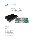
Visual Building Solar Designer User Manual
1 INTRODUCTION
1.1 GENERAL
This manual describes the features of the Solar Designer module used within Visual Building.
With the Solar Design-Plug-in you are able to place PV Modules on roofs and any other areas. After completing
the design you can calculate possible generated power. With this information you can then easily calculate the
income generated from the feed in tariff.
The design process is as follows:
-
Enter the building or the building outline
-
Add dormers, roof windows and chimneys to the roof
-
Define the geographical position and orientation of the building
-
Define the PV Modules size and other technical specifications
-
Calculation is then performed on all entered parameters
-
If required, the shadow calculations can be performed
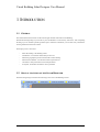
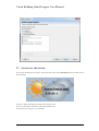
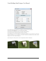
1.2 SPECIAL FEATURES OF THE SOLAR DESIGNER
The Solar Design-Plug-in introduces the following tools to the Visual Building tool bar:
Page 2
Visual Building Solar Designer User Manual
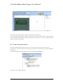
You can show or hide the info panel (the sun and clouds) using the setting in the menu View
Page 3
Visual Building Solar Designer User Manual
2 THE STEPS TO DESIGN A PV-SYSTEM
The creation of the building in the CAD system is both simple and powerful. In this section we will only show the
most important functions. Additional features can be found in the CAD software documentation.
2.1 DESIGN OF THE BUILDING OUTLINE
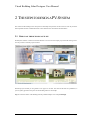
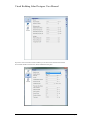
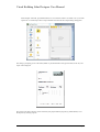
Normally the software is started via the Start Wizard. You can access the sample projects and the training videos.
It is also possible to start the project assistant.
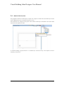
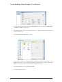
With the project assistant you can generate a new project in seconds. The scale and the units are predefined, so
you can quickly generate a floor plan. See the building outline as an example.
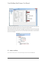
Step 1: Select the outline of the building from the predefined shapes. For example Rectangle
Page 4
Visual Building Solar Designer User Manual
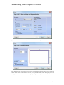
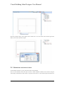
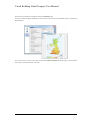
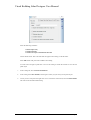
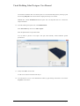
Step 2: Define the external measurements, the wall thickness and the floor heights.
Pressing the Finish button will create new project will be generated and the building outline preview attached to
the mouse. With a mouse click in the 2D or 3D view you can place the building outline. During the preview you
can change the reference point of the outline building by pressing Ctrl + W keys
Page 5
Visual Building Solar Designer User Manual
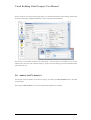
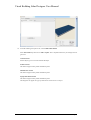
You then insert the building outline in the project with a left mouse button click.
The Assistant generates the numbers of walls to define the room. With the standard features of the CAD system
you can also define all additional parts of the building (walls, windows, doors etc.). This is completely optional
and does not affect the calculations.
2.2 COPY AN ENTIRE FLOOR
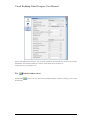
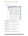
If you have a building with more than one floor, you can copy the active floor with a few mouse clicks.
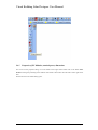
Use the Project viewer on the right side of the window. The active floor will be shown in red. (In this example the
Ground floor)
Select the building in the tree, here Building 1, and click the button New floor above
The New floor above dialog then appears:
Page 6
Visual Building Solar Designer User Manual
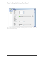
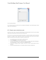
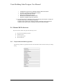
You can then choose different pre defined values of the new floor and define which items will be copied to the
new floor. In this example the ground floor has only 4 external walls. So the select All
If the ground floor already has windows, doors etc included, you can decide to copy only the walls, floors and
ceilings, and optionally the doors and windows. With OK you finish the dialog, the new floor is generated and
the new active floor appears in the project viewer. If you insert elements, these elements are always included in
the active floor of the project.
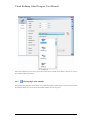
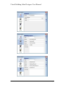
2.3 ADDING THE ROOF
We now add a roof on the 1st floor. Activate the Roof-Plug-in and choose the function Insert roof .
Page 7
Visual Building Solar Designer User Manual
In the How bar, (the second vertical icon bar), you can choose the different options for the roof. (Rectangle,
Polygonal or Insert roof on selected contour)
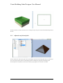
We choose the Insert roof on selected contour function and click the mouse on the building outline either in the
2D or 3D view. If a building outline is detected, it will be shown with a green frame.
Page 8
Visual Building Solar Designer User Manual
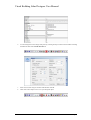
We then insert the roof with a left mouse click. A dialog will open, and you can choose the additional options for
the roof.
2.3.1
Adjust the roof side and pitch
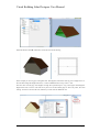
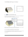
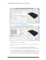
Click on the 3D icon in the lower right corner of the dialog to open the 3D roof image and click on a roof surface.
You will see the properties of the roof side displayed and can change these properties including the pitch.
The example shows a pitched roof, which was created by specifying the two end surfaces as Gables..
Page 9
Visual Building Solar Designer User Manual
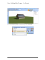
Finish the function with OK, which then inserts the roof into the drawing.
In the example you can see gaps on the gable ends. This happens, because the walls are set to a height of 2.8 m.
We can either change the height of the floor, or insert an additional floor on top of the 1st floor.
This floor will close the gap, if the height is enough. We repeat the steps to copy a floor again and change the
height of the floor to 4.00 m. The walls are by the roof. On the transfer page we select only walls, floor and
ceilings. You have to de-select the roof; otherwise you will create an additional roof..
Page 10
Visual Building Solar Designer User Manual
2.4 ADJUST THE FACING
The geographical direction is defined by the compass. The compass is located in the environment layer and can
only be changed if this layer is activated in the project viewer.
Activate the 2D View, change into the project viewer and activate the layer environment in the context menu
activated with the right mouse button.
As result the building is greyed, because it is on another layer, not the active layer. The compass can now be
selected by a mouse click.
Page 11
Visual Building Solar Designer User Manual
Open the properties dialog of the compass with a double click or use the context menu with the right mouse
button. You can now rotate the compass.
2.5 DEFINITION OF THE LOCATION
For the shadow calculation, you can specify the location of the building.
Note: For the calculation of the solar gain you have to define the global irradiance of the location using the
enclosed map. The definition of the location is a property of the 3D View. Click with the right mouse button in a
Page 12
Visual Building Solar Designer User Manual
free area of the 3D view and open the property dialog. You can define the position of the building with the input
on the sun position page (longitude and latitude) or choose a position from the database.
Alternatively you can define this data in the menu settings – 3D View and save as standard. If you save the
settings all new 3D views work with these settings. If you do not save the settings you lose the information when
you close the 3D view.
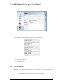
2.6 ADDING THE PV MODULES
For the input of the PV modules you use the PV Plug-in. (activated by the Solar elements button in the What
vertical toolbar)
In the category Solar elements you can choose Thermal Solar modules or PV modules.
Page 13
Visual Building Solar Designer User Manual
2.6.1
Properties of PV Modules, nominal power, dimensions
You can access the properties dialog of a solar module with a right mouse button click on the button Solar
element or during the positioning of the modules click and the context menu activated with a with a right mouse
click.
In both cases the solar element dialog opens.
Page 14
Visual Building Solar Designer User Manual
You can choose the dimensions of the modules, the nominal power and the type of fixing. You can choose
different modules from the catalogue.
Page 15
Visual Building Solar Designer User Manual
If the exact model that you are using is not in the list then choose a model that is similar to the one you want to
use, and then modify the properties.
2.6.2
Placing single solar modules
After changing the properties of the module you can place the module in either the 2D or 3D view with a click of
the left mouse button. You can see the chosen module with the real sizes as preview.
Page 16
Visual Building Solar Designer User Manual
2.6.3
Placing several solar modules in a grid
This tool can help you with a parameter dialog. You can use this dialog if you activate the tool Place in grid. You
can see a preview if you hover the mouse over the roof area.
As long as the modules are not placed, you can change the properties of the modules.
While the modules are attached to the mouse, you can change the reference points with Ctrl+W key combination.
When the modules are placed, you can then make changes on each individual module
2.6.4
Later Changes of the nominal power and other properties
If you want to change the nominal power of the modules, to find the best system for your project, you can use the
function Transfer properties from the context menu or the left hand toolbar, if a module is selected.
See the steps below:
Page 17
Visual Building Solar Designer User Manual
•
Select a module and open the properties dialog with a double click or via the context menu
•
Change the nominal power or any other property
•
Close the properties dialog with OK
•
Select the module with the changes and choose Transfer properties from the context menu
•
Choose the changed property, for example the nominal power from the dialog
•
Then choose the area or layer where you want to transfer the properties to
Page 18
Visual Building Solar Designer User Manual
2.7 ANALYSIS OF THE SYSTEM
You can open the dialog for the analysis of the system with a click on the Solar planer button or double click on
the info window
You have to make some additional settings to get a realistic result.
You can see the number of modules you have placed and the area.
The values for the solar gain etc. are calculated
Page 19
Visual Building Solar Designer User Manual
If you have several roof sides with PV modules you can choose each area from the list field.
For each area the data will be shown. (Pitch, azimuth and solar gain)
Page 20
Visual Building Solar Designer User Manual
The base for all calculations is displayed on the page Parameter page
You have to define the global irradiation for your area. This value can be sourced in different ways. (Internet, EU
documentation)
You can also choose a value on the map with the button Selection location. With the tooltip you can read the
values while you drive the mouse on the map.
Page 21
Visual Building Solar Designer User Manual
System losses influence the solar gain. You can get the information about the efficiency of the inverter from the
manufacturer. The estimated availability is used for system defects like power failure etc.
Conduction losses are included as well.
2.8
SHADING SIMULATION
With the button
in the tool bar you can activate the shading simulation. With the tool dialog you can control
the simulation.
Page 22
Visual Building Solar Designer User Manual
First you define the location and the time. You define the period and time of the simulation.
With the button Start simulation you can start and stop the simulation.
You are able to use a time from a list below if you want to repeat a simulation.
You can delete entries by using the Del button, if the entry is selected.
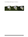
In the simulation you can see the shadows over the period you defined. So you can check if you have any
problems with shading on your PV modules. You are able to define all environmental items in detail, and can
change the sizes of trees, adjacent buildings etc.
See the example with 2 same positions on the 1st of September and the 31st of December.
Page 23
Visual Building Solar Designer User Manual
Page 24
Visual Building Solar Designer User Manual
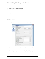
3 PV UNIT ANALYSIS
This dialog consists of three panels:
•
Parameter
•
Calculation
•
PV Unit
3.1 PARAMETER
This is the first panel you should examine, as it contains additional settings that need your attention.
Country must be defined on order to specify the correct map from which you can specify your Global
Irradiance
Power yield per year is the average annual solar radiation depending entirely upon location. This value can be
determined by clicking on the map. In the UK the annual average power yield per year ranges between 950 and
1250 kWh/m2
Page 25
Visual Building Solar Designer User Manual
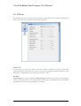
3.2 PV UNIT
The values displayed in this panel are specific to each array, if more than one array is installed on different roof
surfaces. Two arrays on one roof surfaces are treated as a single array.
Selection Area
In some projects you may need to define several arrays, possibly on different roof surface with different
orientation and pitches. This drop down list allows you to select the different areas that the information on this
dialog refers to. Normally there is only a single array and so this is Area 1 / 1
Roof Pitch
The Roof pitch value is used to calculate the Useable solar gain. Nominally set to 30 degrees. (The optimum tilt
relative to a horizontal surface of a solar panel at 1200 on either equinox is calculated as equal to your latitude.
An optimum tilt value for winter can be adjusted by -15 degrees.)
Page 26
Visual Building Solar Designer User Manual
Orientation
This value is determined by the compass. When the roof surface faces South the orientation is 0, when facing
North the orientation is 180 and when facing either West or East the orientation is 90. The Orientation
is used to calculate the Useable solar gain.
A 30 degree pitch West or East facing roof drops the Useable solar gain to 82% of a South facing roof., and a 30
degree pitch North facing roof surface roof drops the Useable solar gain to 61% of a South facing roof.
A 45 degree pitch West or East facing roof drops the Useable solar gain to 77% of a South facing roof., and a 45
degree pitch North facing roof surface roof drops the Useable solar gain to 47.5% of a South facing roof.
Useable Global irradiance
This value is determined by roof pitch and orientation and is nominally 100% for a south facing roof at a 30
degree pitch.
System loss
The System loss is calculated from the Efficiency of the inverter and the Common losses
Useable solar gain
This is calculated from the Power yield per year less system losses
Width of modules
The width of a single module unit. This value is derived from the dimensions entered into the panel object.
Height of modules
The width of a single module unit. This value is derived from the dimensions entered into the panel object.
Area of modules
The area of a single module unit
Nominal Power
The Nominal Power is derived from the value entered into the panel object fot the solar module used on this
specific roof surface
Number of modules
This value is derived from the number solar modules placed on this specific roof surface.
Total output
Calculated from Solar module Nominal Power x Number Panels
Page 27
Visual Building Solar Designer User Manual
3.3 CALCULATION
Area of modules
Calculated from Panel Width x Panel Height x Number of Modules
The Panel Width x Panel Height are derived from the dimensions entered into the panel object.
In the report generator this value is represented by the Module_Area variable
Number of Modules
The Number of modules is derived from the number of panels placed on the roof.
In the report generator this value is represented by the Number_of_Modules variable
Installed Nominal Power
Calculated from Nominal Power x Number of Modules
The Nominal Power is derived from the value entered into the panel object.
Nominal Power per m2
Calculated from Installed Nominal Power / Number of modules
In the report generator this value is represented by the Nominal_Power_total variable
Generated Power per m2
Calculated from Generated power per year / Area of solar modules
In the report generator this value is represented by the Generated_Power_per_sqm variable
Page 28
Visual Building Solar Designer User Manual
Generated Power per year
Calculated from Installed Nominal Power x Power Yield per year
In the report generator this value is represented by the Generated_Power_per_year variable
Feed-in tariff per year
In the report generator this value is represented by the Feed_on_tariff_sqm variable
Feed-in tariff pr m2
In the report generator this value is represented by the Feed_on_tariff_per_year variable
Average feed-in tariff
In the report generator this value is represented by the Average_Feed_in_tariff variable
Page 29
Visual Building Solar Designer User Manual
4 CREATE A NEW SOLAR PANEL
4.1 CREATE NEW PANEL
Before you start, you will need the following details concerning your new solar panel:
Product Name
*Product web link
Manufacturer’s name
*Manufacturers web link
*PDF specification file
Panel external dimensions (width x height x depth in cm)
Panel Nominal Power
*Additional text information you want to display about the panel
*Additional popup image you want to display about the panel
*Optional
1.
Create a new project (Ctrl + N)
2.
Create a 3D View of this new project (Alt+W, N), and arrange the windows vertically so you can view
both windows.
3.
In the catalog, select Construction element from the top catalog icon bar, then select the Solar modules
catalog folder
4.
From the catalog select any panel, and drag it into a new project (either into the 2D or 3D view) while
holding down the Ctrl key down.
Right click on the solar panel object and select properties.
You will see the existing properties for the existing panel, which we are now going to edit.
Page 30
Visual Building Solar Designer User Manual
5.
In the 3D Object Properties panel select the Scale distorted checkbox and adjust the Width, Height
and Depth. Click OK to accept the edits.
6.
Select the panel object in the 3D view, and then press Alt + x, 3, Return (selecting the Export menu, 3D
Formats, 3D Object file).
This will activate the Save Object file as... dialog.
In this dialog navigate to Catalog/AEC/Solar Elements/Solar modules and navigate to the
manufacturer’s folder. (You can create a new folder for a manufacturer by selecting Create New
Folder... in the top of this dialog, and then entering the Manufacturer’s name.)
Enter the file name for your new panel, and select OK
The Export project is activated.
Page 31
Visual Building Solar Designer User Manual
Select the following Checkbox:
Selected objects only
Combine materials
Combine sub-objects with identical materials
Add or edit the Name. This is the name that will appear in the catalog, not the file name.
Select OK and the solar panel will be added to the Catalog.
You will need to navigate up and down a level in the catalog to refresh the contents to view the new
panel object.
7.
In the Catalog tab, select Construction Elements
8.
In the catalog select Solar modules, and navigate to where you just saved you new panel object.
9.
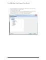
Locate your new solar panel and right click on it to activate the context menu, and select Edit Chunks.
This will activate the Edit Chunks dialog:
Page 32
Visual Building Solar Designer User Manual
10. From the ChunkType drop down list, select Common information
Select This chunk drop down list to Add or replace. This is important otherwise your changes will not
get saved.
General Section
Ensure Object type is set to Solar element 3D-Object
Product Section
This data will appear in the product information panel
Manufacturer Section
This data will appear in the product information panel
Popup Information Section
This data will appear in the product information panel
The image file will appear as a pop up when mouse cursor hovers over object
Page 33
Visual Building Solar Designer User Manual
11. From the ChunkType drop down list, select Roof panel element
Select This chunk drop down list to Add or replace.
The Contour points are used only for roof integrated mounting. This is ignored for Roof surface
mounting.
If your panel is roof integrated, then select Object details to Roof integrated mounting.
You should also specify if your panel is a Photovoltaic Solar Module or a Solar Thermal Collector
For a roof integrated mounting, enable the Preview option Show opening solid, as this will then
show the area defined by the contour points. The Show parent plane will display the roof plane in the
preview window. The contour points are the area around the panel that is cut away into the roof. The
points can automatically be generated by clicking on the Find contour button. The Round coordinates
Page 34
Visual Building Solar Designer User Manual
will round the calculated values to 4 decimal places. You can edit individual points by selecting a point
and selecting Edit point. The result of the edit is displayed in the preview window
IMPORTANT: Add the Nominal Power for this panel. This is an important value as it is used in the
output calculations.
12. From the ChunkType drop down list, select PDF Document
Select This chunk drop down list to Add or replace.
Select the pdf document via Open File button.
You can attach a pdf file to the object. This pdf would normally contain additional product
specifications.
13. Finally select OK to save the edits
You have now created a new Solar Panel object.
14. You can allocate a icon to a new manufacturers folder by right clicking on the folder to activate the
Properties context menu
Page 35
Visual Building Solar Designer User Manual
You can edit the folder name.
You can load an image file to be used as an icon, by clicking on the image file. We recommend using a 128x128
image with a white background.
4.2 CREATE COPY OF EXISTING PANEL
The previous section creates a new panel without retaining any of the original panel’s values. If you are creating a
range of panels with mostly the same values this can become tiresome.
You can also use an existing solar panel module and reproduce it several times replacing only the specifications
that differ. For example a range of panels may have the same specifications and only the power output is
different. The dimensions and the web links, and .pdf file all remain the same.
1.
Copy the panel giving it a new file name (in windows explorer)
2.
Use the ChunkEditor to edit the panels name and power
3.
You will see that although you have a different file name, the catalogue name remains unchanged, so
4.
In the top file navigation window, navigate to the object you want to edit and load the object by
5.
In the bottom left properties panel, you can edit the Name and web links, and dimensions
use the 3D Converter to rename the catalogue name. Run 3D Converter
selecting it.
Page 36
Visual Building Solar Designer User Manual
6.
You can change the texture image of the panel by selecting the object centre texture and then activating
the Material editor with the Edit material icon
7.
Select a new texture using the Texture field and then click OK
8.
Then click on Save Object icon to save your edit panel object
Page 37
Visual Building Solar Designer User Manual
Page 38
Visual Building Solar Designer User Manual
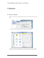
5 REPORTS
5.1 RUNNING A REPORT
Reports are run from the menu: Export/Reports/Reports/Solar Analysis menu and activates the Properties
dialog:
To select a report click on the Template path field. To activate the Open Report Dialog:
All reports are .lst files and care must be made to select only reports related to Solar panels, as reports for
other parts of the system also reside here. We suggest you prefix all reports names associated with the
Page 39
Visual Building Solar Designer User Manual
Solar Designer with Solar, eg SolarEstimation1.lst. You could also create a new folder to save your Solar
reports into. To run the report select a report and then click OK. The Save Report dialog then appears:
This dialog is prompting you for a file name (default is .pdf, but alternative file types are html,xls and .rtf). The
report is then displayed:
Note, if the report fails to display, please ensure that your pdf presentation program (eg Adobe Reader) is not
already actively showing a report.
Page 40
Visual Building Solar Designer User Manual
5.2 EDITING A REPORT
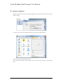
Reports are edited from the menu: Export/Reports/Reports/Solar Analysis menu which then activates the
Properties dialog:
To select a report, click on the Template path field. To activate the Open Report Dialog:
Select the report to be edited and the select OK.
Now click on Edit Template, which will then activate the List & Label program, the report template
editor.
Page 41
Visual Building Solar Designer User Manual
Overview of List & Label:
Object List Window
This where you create your objects to be displayed within your report (default left hand window)
Variable List Window
This window contains all the variables visible to List & Label. (default left hand window)
Page 42
Visual Building Solar Designer User Manual
Layout Window
This is where you will place your objects to be displayer. (default centre window). This window also
contains Layout Preview and Preview tabs.
5.3 CREATING A NEW REPORT
Normally it’s easier to edit an existing report, rather from starting with a blank report, especially as most
of your reports will contain the same variables, but with different calculations and layout.
Page 43
Visual Building Solar Designer User Manual
If you do want to create a new blank report, then after loading an existing report, click on File / New (Alt
+ F, N). You should then save the new report template, to be sure not to overwrite the report that you
loaded, using File/Save As menu (Alt + F, A) .
Be sure to save the file in:
C:\Program Files\Visual Building Solar Designer\Templates\English
5.3.1
Create a logo
For your company logo, please use a .gif or .png file. We also need to create a "Picture" object. Proceed
as follows:
a) In the "Objects" toolbar, choose the "Picture" object type.
b) In the workspace, point the mouse to the position where the upper left corner of the
object is to begin. The mouse cursor changes to a crosshair. Hold down the left
mouse button and drag the crosshair to the lower right corner of the planned object.
Release the mouse button when the object (the dashed border) is the right size.
c) A file selection dialog will appear. Select the image file that you want.
d) After you select the file, the logo will be inserted. In addition, you can insert the
picture into the project by enabling the ("Embed image in project file" checkbox
option. This option copies the image to the project thus making it available even
without the external file.
e) In the Properties panel, you can change the objects properties, such Keep
proportions, and Position.
So you have now created your first object in your report! You can view the logo by clicking on
the Preview tab.
5.3.2
Add a Text Label
You can use a text object to add a title to the report. Text objects let you place text in the workspace. As well as
fixed text, you can also insert the contents of fields (variables) from the database (e.g. company name), or you
can use functions (page number, date etc.).
a) In the "Objects" toolbar, choose the "Text" object type.
b) In the workspace, hold down the left mouse button and pull the object to the required
size.
c) The formula wizard will now appear which you can use to define the contents of the
text object.
d) This dialog consists of a series of tabs each containing different elements to be
edited. The following chapters explain the meanings of these elements in more detail.
Page 44
Visual Building Solar Designer User Manual
•
•
•
•
•
•
Variables and Functions: the available variables, fields and functions.
Condition: for defining IF-THEN-ELSE conditions.
Text: for entering fixed text and tabs.
Date Format: different date formats.
Number Format: different number formats.
Operators: available conjunction operators.
e) You can also enter the expression that you want directly in the edit box or modify the
text that is there (e.g. put something in brackets).
Therefore, enter our title "List of products" directly. Fixed text must be enclosed in
quotation marks. Enter names of variables and functions without brackets.
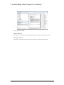
5.4 REPORT DATA SOURCES
Reports are based on data coming from the following sources:
5.4.1
a)
Project name and address properties
b)
Calculated values
c)
The solar panel object
d)
The solar data file
Project name and address properties
The following variables are generated from the name and address details entered in the Project settings
dialog.
Page 45
Visual Building Solar Designer User Manual
Page 46
Visual Building Solar Designer User Manual
5.4.2
Calculated values
These values are calculated and displayed in the PV unit Analysis function:
Note that some of these values are calculated from values derived from the actual object:
5.4.3
•
Panel Nominal Power
•
Panel dimensions
The solar data file
The data file is a CSV list of additional properties for each solar panel. The list is called Solar.csv and is
located in:
C:\Program Files\Visual Building Solar Designer\Templates\English
Page 47
Visual Building Solar Designer User Manual
And appears in the following format:
Datei;Bezeichnung;Artikelnummer;Beschreibung;#.#Preis
140x113.cyg;Mein Modul;Test Panel;Meine Beschreibung;123.45
YL185P23b.cyg;YL 185 P23b;YL185;Solar Panel;500.00
131x90.cyg;;;;500.00
The first line contains the data variable names that are imported into the report generator. Each variable is
separated by a semi-colon.
Page 48