1
User Manual
Using the Mining, Mineral, and Cement Library
(MMCL) in FactoryTalk View Site Edition
Applications
Important User Information
Solid-state equipment has operational characteristics differing from those of electromechanical equipment. Safety
Guidelines for the Application, Installation and Maintenance of Solid State Controls (publication SGI-1.1 available from
your local Rockwell Automation sales office or online at http://www.rockwellautomation.com/literature/) describes some
important differences between solid-state equipment and hard-wired electromechanical devices. Because of this difference,
and also because of the wide variety of uses for solid-state equipment, all persons responsible for applying this equipment
must satisfy themselves that each intended application of this equipment is acceptable.
In no event will Rockwell Automation, Inc. be responsible or liable for indirect or consequential damages resulting from
the use or application of this equipment.
The examples and diagrams in this manual are included solely for illustrative purposes. Because of the many variables and
requirements associated with any particular installation, Rockwell Automation, Inc. cannot assume responsibility or
liability for actual use based on the examples and diagrams.
No patent liability is assumed by Rockwell Automation, Inc. with respect to use of information, circuits, equipment, or
software described in this manual.
Reproduction of the contents of this manual, in whole or in part, without written permission of Rockwell Automation,
Inc., is prohibited.
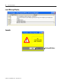
Throughout this manual, when necessary, we use notes to make you aware of safety considerations.
WARNING: Identifies information about practices or circumstances that can cause an explosion in a hazardous
environment, which may lead to personal injury or death, property damage, or economic loss.
ATTENTION: Identifies information about practices or circumstances that can lead to personal injury or death,
property damage, or economic loss. Attentions help you identify a hazard, avoid a hazard, and recognize the
consequence
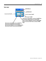
SHOCK HAZARD: Labels may be on or inside the equipment, for example, a drive or motor, to alert people that
dangerous voltage may be present.
BURN HAZARD: Labels may be on or inside the equipment, for example, a drive or motor, to alert people that
surfaces may reach dangerous temperatures.
IMPORTANT
Identifies information that is critical for successful application and understanding of the product.
Allen-Bradley, ControlLogix, FactoryTalk, FactoryTalk Services Platform, FactoryTalk View SE, FactoryTalk View Studio, Rockwell Software, Rockwell Automation, RSLinx Enterprise, RSLogix 5000, RSView Enterprise,
and TechConnect are trademarks of Rockwell Automation, Inc.
Trademarks not belonging to Rockwell Automation are property of their respective companies.
Table of Contents
Preface
Introduction . . . . . . . . . . . . . . . . . . . . . . . . . . . . . . . . . . . . . . . . . . . . . . . 5
Requirements . . . . . . . . . . . . . . . . . . . . . . . . . . . . . . . . . . . . . . . . . . . . . . 5
Before You Begin. . . . . . . . . . . . . . . . . . . . . . . . . . . . . . . . . . . . . . . . . . . 5
MMCL Deliverables . . . . . . . . . . . . . . . . . . . . . . . . . . . . . . . . . . . . . . . . . 6
Reference Documents . . . . . . . . . . . . . . . . . . . . . . . . . . . . . . . . . . . . . . . 8
Chapter 1
Developing an HMI Application
Prerequisites . . . . . . . . . . . . . . . . . . . . . . . . . . . . . . . . . . . . . . . . . . . . . . . 9
Create a New Project . . . . . . . . . . . . . . . . . . . . . . . . . . . . . . . . . . . . . . . . 9
Data Server Setup. . . . . . . . . . . . . . . . . . . . . . . . . . . . . . . . . . . . . . . . . . 12
Import Templates from the Library Project . . . . . . . . . . . . . . . . . . . . . 16
Displays . . . . . . . . . . . . . . . . . . . . . . . . . . . . . . . . . . . . . . . . . . . . . . 16
Images. . . . . . . . . . . . . . . . . . . . . . . . . . . . . . . . . . . . . . . . . . . . . . . . 17
Macros . . . . . . . . . . . . . . . . . . . . . . . . . . . . . . . . . . . . . . . . . . . . . . . 17
Events. . . . . . . . . . . . . . . . . . . . . . . . . . . . . . . . . . . . . . . . . . . . . . . . 17
Derived Tags . . . . . . . . . . . . . . . . . . . . . . . . . . . . . . . . . . . . . . . . . . 18
Import Tags with the Data Retrieval Tool . . . . . . . . . . . . . . . . . . . . . . 19
Manually Created Tags . . . . . . . . . . . . . . . . . . . . . . . . . . . . . . . . . . . . . . 20
User Accounts . . . . . . . . . . . . . . . . . . . . . . . . . . . . . . . . . . . . . . . . . . . . 21
Import the MMCL Project . . . . . . . . . . . . . . . . . . . . . . . . . . . . . . . . . . 23
Creating New FTView SE Displays . . . . . . . . . . . . . . . . . . . . . . . . . . . 27
00_Header . . . . . . . . . . . . . . . . . . . . . . . . . . . . . . . . . . . . . . . . . . . . 27
00_Footer . . . . . . . . . . . . . . . . . . . . . . . . . . . . . . . . . . . . . . . . . . . . . 29
User displays. . . . . . . . . . . . . . . . . . . . . . . . . . . . . . . . . . . . . . . . . . . 29
Creating Equipment . . . . . . . . . . . . . . . . . . . . . . . . . . . . . . . . . . . . . . . . 40
Modifying Graphic Objects . . . . . . . . . . . . . . . . . . . . . . . . . . . . . . . . . . 41
Selection Buttons for Machine Groups (MaGrp). . . . . . . . . . . . . . . . . 41
System Display . . . . . . . . . . . . . . . . . . . . . . . . . . . . . . . . . . . . . . . . . . . . 42
Communication Supervision . . . . . . . . . . . . . . . . . . . . . . . . . . . . . . . . . 43
Trends . . . . . . . . . . . . . . . . . . . . . . . . . . . . . . . . . . . . . . . . . . . . . . . . . . . 45
Alarming . . . . . . . . . . . . . . . . . . . . . . . . . . . . . . . . . . . . . . . . . . . . . . . . . 46
Digital Alarms . . . . . . . . . . . . . . . . . . . . . . . . . . . . . . . . . . . . . . . . . 47
Analog Alarm . . . . . . . . . . . . . . . . . . . . . . . . . . . . . . . . . . . . . . . . . . 48
Derived Tags - Alarming . . . . . . . . . . . . . . . . . . . . . . . . . . . . . . . . . 49
Chapter 2
Runtime Operation
3
Common Operations . . . . . . . . . . . . . . . . . . . . . . . . . . . . . . . . . . . . . . . 51
Singlestart . . . . . . . . . . . . . . . . . . . . . . . . . . . . . . . . . . . . . . . . . . . . . 51
Acknowledge . . . . . . . . . . . . . . . . . . . . . . . . . . . . . . . . . . . . . . . . . . 52
Local Mode . . . . . . . . . . . . . . . . . . . . . . . . . . . . . . . . . . . . . . . . . . . 52
Info Function . . . . . . . . . . . . . . . . . . . . . . . . . . . . . . . . . . . . . . . . . . 53
Value Input. . . . . . . . . . . . . . . . . . . . . . . . . . . . . . . . . . . . . . . . . . . . 53
Analog/Actuator Module . . . . . . . . . . . . . . . . . . . . . . . . . . . . . . . . 54
PID Module . . . . . . . . . . . . . . . . . . . . . . . . . . . . . . . . . . . . . . . . . . . 55
E50 Example . . . . . . . . . . . . . . . . . . . . . . . . . . . . . . . . . . . . . . . . . . 58
Publication RA-UM001B-EN-P - November 2010
Table of Contents
4
Appendix A
Display Tag Reference
Publication RA-UM001B-EN-P - November 2010
Control Group . . . . . . . . . . . . . . . . . . . . . . . . . . . . . . . . . . . . . . . . . . . . 60
MotorN. . . . . . . . . . . . . . . . . . . . . . . . . . . . . . . . . . . . . . . . . . . . . . . . . . 62
MotorN_E3 . . . . . . . . . . . . . . . . . . . . . . . . . . . . . . . . . . . . . . . . . . . . . . 63
MotorR . . . . . . . . . . . . . . . . . . . . . . . . . . . . . . . . . . . . . . . . . . . . . . . . . . 64
MotorR_E3. . . . . . . . . . . . . . . . . . . . . . . . . . . . . . . . . . . . . . . . . . . . . . . 66
MotorD. . . . . . . . . . . . . . . . . . . . . . . . . . . . . . . . . . . . . . . . . . . . . . . . . . 68
MotorD_E3 . . . . . . . . . . . . . . . . . . . . . . . . . . . . . . . . . . . . . . . . . . . . . . 70
SubSys . . . . . . . . . . . . . . . . . . . . . . . . . . . . . . . . . . . . . . . . . . . . . . . . . . . 72
Analog Enhanced . . . . . . . . . . . . . . . . . . . . . . . . . . . . . . . . . . . . . . . . . . 73
Analog. . . . . . . . . . . . . . . . . . . . . . . . . . . . . . . . . . . . . . . . . . . . . . . . . . . 75
ActMod. . . . . . . . . . . . . . . . . . . . . . . . . . . . . . . . . . . . . . . . . . . . . . . . . . 77
PIDMod . . . . . . . . . . . . . . . . . . . . . . . . . . . . . . . . . . . . . . . . . . . . . . . . . 79
Valve1 . . . . . . . . . . . . . . . . . . . . . . . . . . . . . . . . . . . . . . . . . . . . . . . . . . . 81
Valve2 . . . . . . . . . . . . . . . . . . . . . . . . . . . . . . . . . . . . . . . . . . . . . . . . . . . 83
DigInp. . . . . . . . . . . . . . . . . . . . . . . . . . . . . . . . . . . . . . . . . . . . . . . . . . . 85
DigInp2. . . . . . . . . . . . . . . . . . . . . . . . . . . . . . . . . . . . . . . . . . . . . . . . . . 86
DigPulse . . . . . . . . . . . . . . . . . . . . . . . . . . . . . . . . . . . . . . . . . . . . . . . . . 87
Local Message Display . . . . . . . . . . . . . . . . . . . . . . . . . . . . . . . . . . . . . . 88
CommErr . . . . . . . . . . . . . . . . . . . . . . . . . . . . . . . . . . . . . . . . . . . . . . . . 88
Value Input . . . . . . . . . . . . . . . . . . . . . . . . . . . . . . . . . . . . . . . . . . . . . . . 89
SysGrp . . . . . . . . . . . . . . . . . . . . . . . . . . . . . . . . . . . . . . . . . . . . . . . . . . 90
Rockwell Automation Support . . . . . . . . . . . . . . . . . . . . . . . . . . . . . . . 91
Installation Assistance . . . . . . . . . . . . . . . . . . . . . . . . . . . . . . . . . . . 91
New Product Satisfaction Return . . . . . . . . . . . . . . . . . . . . . . . . . . 91
Preface
Introduction
Requirements
This document provides a description of how to create an application with
FactoryTalk View Site Edition based on the Mining, Mineral, and Cement
Library (MMCL). It does not show product installation or setup of IT
infrastructure.
Item
Requirements
Software
• FactoryTalk View Site Edition 5.0 or higher
• RSLinx Enterprise 5.0
• FactoryTalk Services Platform 2.10 or higher
Hardware
• HMI/Data Servers
• Client Computers
• Engineering Computer with FactoryTalk View Studio
Skills
• Windows Domain administering
• FactoryTalk View Site Edition 5.0 development
• FactoryTalk directory configuration
• Visual Basic for Application programming
Before You Begin
Before starting application development, the following information must be
obtained.
Item
Requirements
IT infrastructure
• Definition of HMI servers (names)
• Definition of Data Servers (FactoryTalk)
• Definition of Clients
• Definition of user groups/users (domain controller)
ControlLogix
controllers
Definition of shortcuts for communication
Data Retrieval Tool For each shortcut, a FactoryTalk View SE Tag file and a FactoryTalk
data files
View SE Alarm file must be created with the Data Retrieval Tool.
Data Retrieval Tool data must be complete prior to using the HMI
development environment.
Application files
5
Contact your local Rockwell Account Manager for files.
Publication RA-UM001B-EN-P - November 2010
6
Preface
MMCL Deliverables
Publication RA-UM001B-EN-P - November 2010
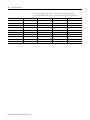
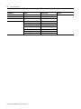
The MMCL project contains display templates for the following modules.
Module
Description
Display Template Names
MotorN
Normal Motor DOL
03_MotorN_small
03_MotorN_large
03_MotorN_param
000_Sim_MotorN
MotorN & E3p
Normal Motor DOL with
E3plus
03_MotorN_E3_small
03_MotorN_E3_large
000_Sim_MotorN_E3p
MotorR
Reverse Motor
03_MotorR_small
03_MotorR_large
03_MotorR_param
000_Sim_MotorR
MotorR & E3p
Reverse Motor with E3plus
03_MotorR_E3_small
03_MotorR_E3_large
000_Sim_MorotR_E3p
MotorD
Damper Motor
03_MotorD_small
03_MotorD_large
03_MotorD_param
000_Sim_MotorD
MotorD & E3p
Damper Motor with E3plus
03_MotorD_E3_small
03_MotorD_E3_large
000_Sim_MotorD_E3p
SubSys
Subsystem
03_SubSys_large
03_SubSys_small
03-SubSys_param
DigInp
Digital Input
04_DigInp
04_DigInp_param
000_sim_DigInp
DigInp2
Drift switch/Digital input
module with 2 inputs
04_DigInp2
04_DigInp2_param
000_Sim_DigInp2
Valve1
Valve with 1 position
03_Valve1_small
03_Valve1_large
03_Valve1_param
000_Sim_Valve1
Valve2
Valve with 2 positions
03_Valve2_small
03_Valve2_large
03_Valve2_param
000_Sim_Valve2
AnInp
Analog input
05_AnaInp
05_AnaInp_param
000_Sim_AnaInp
AnInpC
Analog input module with
enhanced Control
05_AnaInpC_small
05_AnaInpC_large
05_AnaInpC_param
Preface
Module
Description
Display Template Names
ActMod
Actuator Module
05_ActMod_small
05_ActMod_large
05_ActMod_param
000_Sim_ActMod
PidMod
PID Module
06_PidMod
06_PidMod_param
000_Sim_PidMod
CtrlGrp
Control Group Module
11_CtrlGrp
11_CtrlGrp_param
SysGrp
System Group
11_SysGrp
11_SysGrp_param
IPCom
Inter Process
Communication Module
NA
Motor2N
Two Speed Motor
03_Motor2N_small
03_Motor2N_large
Valve3
Valve with 3 positions
03_Valve3_large
03_Valve3_small
DigPulse
Digital Pulse Input
04_DigPulse
04_DigPulse_param
000_Sim_DigPulse
7
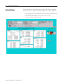
The MMCL project also provides the following sample displays.
Sample Display Provided
Description
Alarms
Alarm screen
Main
Main Screen for startup purpose
E50 Test Group
E50 Test Group screen
Crusher Group
Crusher Screen
RA_CEM_Library
Library screen with sample elements
Library_Graphics
Graphics Library for industrial applications
Network
Sample screen for Network supervision
System
Sample Screen of a system information screen
TrendA, TrendB
Sample Screen of a trend
Footer, Alarm Footer, Trend
Footer
Sample Screen of a Footer
Header
Sample Screen of a Header
Publication RA-UM001B-EN-P - November 2010
8
Preface
Reference Documents
• FactoryTalk View Site Edition User’s Guide,
publication VIEWSE-UM006
• Integrating the Mining, Mineral, and Cement Library (MMCL) into
RSLogix 5000 Applications, publication RA-RM002A-EN-P
• Using the Mining, Mineral, and Cement Library (MMCL) in
RSLogix 5000 Applications, publication RA-UM002B-EN-P
Publication RA-UM001B-EN-P - November 2010
Chapter
1
Developing an HMI Application
Prerequisites
Create a New Project
The creation of a HMI Application is based on the following files.
File
Source
MMCLibrary (FactoryTalk View Site Edition Project)
Library
HMITag-[shortcut name].csv
Data Retrieval Tool
Alarms-[shortcut name].csv
Data Retrieval Tool
HMIDerivedTags-[shortcut name].csv
HDRS Data Retrieval Tool
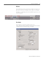
Complete the following procedure to create a new project.
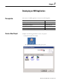
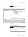
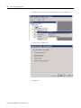
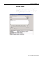
1. Start FactoryTalk View Studio.
The Application Type selection dialog box opens.
9
Publication RA-UM001B-EN-P - November 2010
10
Developing an HMI Application
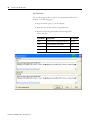
2. Select Site Edition (Network) and click Continue.
The Log On to FactoryTalk dialog box opens.
3. Enter your User name and Password and click OK.
The New/Open Site Edition (Network) Application dialog box opens.
4. On the New tab, enter a name for the overall project.
5. Select the language which corresponds to the regional setting of the
computer.
You will be able to translate the application into any other language at a
later state of development.
6. Click Create.
The FactoryTalk View window opens.
Publication RA-UM001B-EN-P - November 2010
Developing an HMI Application
11
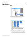
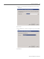
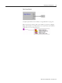
7. To split the project into different areas hosting an HMI Server,
right-click the CEM project and select New Area.
8. Type an area name and click OK.
9. Right-click the newly created area and select Add New Server > HMI
Server.
10. Select Create a new HMI server and click Next.
Publication RA-UM001B-EN-P - November 2010
12
Developing an HMI Application
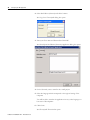
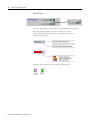
11. Type a name and description for the new HMI server.
12. Type or browse to the computer name that will host the new server.
13. Click Finish.
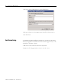
Data Server Setup
To communicate with the different controllers on the network, a data server
must be configured. For communication with ControlLogix processors, we are
using RSLinx Enterprise software.
A data server can be created for each area or per project.
Complete the following procedure to create a new data server.
Publication RA-UM001B-EN-P - November 2010
Developing an HMI Application
13
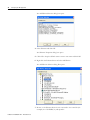
1. Right-click the newly created area and select Add New Server >
Rockwell Automation Device Server (RSLinx Enterprise).
The new data server is created.
2. To add a new driver, double-click Communication Setup.
The Communication Setup dialog box opens.
3. Right-click RSLinx Enterprise and select Add Driver
Publication RA-UM001B-EN-P - November 2010
14
Developing an HMI Application
The Add Driver Selection dialog box opens.
4. Select Ethernet and click OK.
The Ethernet Properties dialog box opens.
5. Click OK to keep the default name or enter a new name and click OK.
6. Right-click the Ethernet driver and select Add Device.
The Add Device Selection dialog Box opens.
7. Browse to the Ethernet device that is connected to the controller (for
example, the 1756-ENBT/A) and expand it.
Publication RA-UM001B-EN-P - November 2010
Developing an HMI Application
15
8. Select the revision that corresponds to your Ethernet device and click
OK.
TIP
In the following steps you create shortcuts to the HMI tags
in your controllers.
9. Browse to the controller and select it.
10. Click Add.
11. Type a shortcut name (do not use spaces) which corresponds to name
defined in the Data Retrieval Tool.
IMPORTANT
The shortcut name must correspond to the defined name
in the Data Retrieval Tool. These defined names can be
found within the file names of the files exported by the
Data Retrieval Tool (for example,
HMITag-[shortcut name].csv). The exported files are in the
Data Retrieval Tool directory.
12. Click Apply.
13. Repeat steps 1–12 for each controller.
Publication RA-UM001B-EN-P - November 2010
16
Developing an HMI Application
Import Templates from the
Library Project
In this section, the display templates are loaded into the empty HMI project.
Displays
1. Expand the project until the Graphics folder is expanded.
2. Right-click Display and select Add Component Into Application.
3. Browse to the Library Project and open the Gfx folder.
4. Select all the files in the folder and click Open.
The display templates and sample screens are imported into your
project.
Note: To properly utilize some graphic files migrated from Process
Control group, before adding display graphics Global Object graphics
should be added first. The steps to add Global Object graphics are the
same to adding display graphics. The Global Object graphics are stored
in the GGfx folder.
Publication RA-UM001B-EN-P - November 2010
Developing an HMI Application
17
Images
In this section bitmap images, which are used in the display templates, are
imported into the project.
1. Right-click Images and select Add Component Into Application.
2. Browse in the Library Project to the Images folder.
3. Select all the files in the folder and click Open.
The images are imported into your project.
Macros
In this section macros, which provide Startup and Shutdown batch commands,
are imported into the project.
1. Right-click Macro and select Add Component Into Application.
2. Browse in the Library Project and open the Mcr folder.
3. Select all the files in the folder and click Open.
The macros are imported into your project.
Events
In this section an event file, for communication supervision, is imported into
the project.
1. Right-click Events and select Add Component Into Application.
2. Browse in the Library Project and open the EDS folder.
3. Select the .eds file and click Open.
The event file is imported into your project.
Publication RA-UM001B-EN-P - November 2010
18
Developing an HMI Application
Derived Tags
In this section, a derived tag file, for heartbeat handshake with a ControlLogix
controller, is imported into the project.
1. Right-click Derived Tags and select Add Component Into Application.
2. Browse in the Library Project and open the DTS folder.
3. Select the heartbeatfct.dts file and click Open.
4. The derived file is imported into your project.
Publication RA-UM001B-EN-P - November 2010
Developing an HMI Application
Import Tags with the Data
Retrieval Tool
19
The Data Retrieval Tool can export all the required tag and alarm settings for
each object used in FactoryTalk View SE. The following three files are
generated for each processor:
• HMITag-[shortcut name].csv
• Alarms-[shortcut name].csv
• HMIDerivedTags-[shortcut name].csv
Where [shortcut name] is the shortcut created in the Communication Setup.
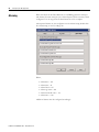
1. Under Tools select Tag Import and Export Wizard.
The Tag Import and Export Wizard dialog box opens.
2. Verify that Import FactoryTalk View tag CSV files is selected and click
Next.
3. Verify that Site Edition is selected for the Project type and click Next.
Publication RA-UM001B-EN-P - November 2010
20
Developing an HMI Application
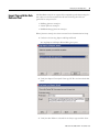
4. Browse to the .eds file for the project into which you want to import the
tags and click Next.
5. Browse to the .csv files for the Tags and Alarms which you want to
import and click Next.
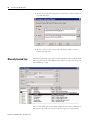
Manually Created Tags
The following memory tags must be created manually in FactoryTalk View SE.
These tags are used for some MMCL functionalities. To open this dialog box,
select HMI Tags > Tags.
Also, a Client folder with its sub folders (depends on how many HMI clients)
and memory tags need to be created to allow navigation to work properly.
Publication RA-UM001B-EN-P - November 2010
Developing an HMI Application
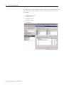
User Accounts
21
The following five security accounts must be created in FactoryTalk View SE
for the library templates:
•
•
•
•
•
Administrators
Engineers
Electricians
Operators
Viewers
To open this dialog box, under Settings, select Runtime Security.
Publication RA-UM001B-EN-P - November 2010
22
Developing an HMI Application
To assign security codes to different accounts, press Security Accounts button
and the Security window opens. The security code assignment to each account
is as follows:
•
•
•
•
•
Publication RA-UM001B-EN-P - November 2010
Administrators: A-P
Engineers: A-E
Electricians: A-C
Operators: A,B
Viewers: A
Developing an HMI Application
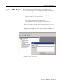
Import the MMCL Project
23
Instead of importing the individual elements of the MMCL project
one-by-one, the entire project can be imported and used as a base project.
Complete the following steps to import the project.
1. Copy the MMCL_HMI_Server_V2.zip file (or appropriate version)
from the MMCL CD to your hard drive.
2. Unzip the file into the working directory of FactoryTalk View SE.
For example: C:\Documents and Settings\All
Users\Documents\RSView Enterprise\SE\HMI Projects
3. In FactoryTalk View Studio, create a new Application if you do not
already have one open.
4. Right-click the Application name (in this example, CEM_Plant) and
select New Area.
5. Enter a name and click OK.
Publication RA-UM001B-EN-P - November 2010
24
Developing an HMI Application
6. Right-click the new area and select Add New Server > HMI Server.
7. Select Copy an HMI server.
8. Click Next.
Publication RA-UM001B-EN-P - November 2010
Developing an HMI Application
25
9. Browse to or enter the name of the computer that hosts the existing
HMI server.
10. Click Next.
11. Select MMCLibrary_v2 which was unzipped in step 2 from the MMCL
CD.
12. Click Next.
Publication RA-UM001B-EN-P - November 2010
26
Developing an HMI Application
13. Enter a name for the new server.
14. Click Finish.
15. Follow the steps in Data Server Setup on page 12 to add a new Data
Server.
Note: MMCL_HMI_Server_V2.zip also contains four other HMI server
folders which store overview graphics for different areas/departments in
Cement Industry for user reverence. They are MMC_Auxiliaries,
MMC_CementMills, MMC_Kiln, and MMC_RawMaterials.
Publication RA-UM001B-EN-P - November 2010
Developing an HMI Application
Creating New FactoryTalk
View SE Displays
27
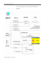
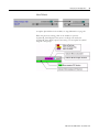
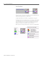
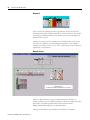
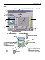
00_Header
00_Header Display must be configured always as startup page and may not be
closed at any time. This page contains Visual Basic code for supervising the
communication to the controller(s). It is monitoring the HMI tag “ComERR”
and popup the screen “20_ComErr”.
The HMI Tag ComErr is generated by the ComErr Event which is monitoring
the Heartbeat tag for communication errors.
If you want to monitor several processors for a communication error,
additional tags and expressions must be added to the Visual Basic code in the
00_Header Display and the ComErr Event.
Publication RA-UM001B-EN-P - November 2010
28
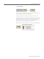
Developing an HMI Application
Communication Supervision of a Controller and FactoryTalk View SE
HMI Tag
Publication RA-UM001B-EN-P - November 2010
Developing an HMI Application
29
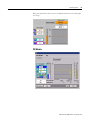
00_Footer
The 00_FTUserLogon macro opens the 00_Footer display at startup. You can
place a plant overview onto this display in order to jump to any sub-displays.
This display is a sample display which can be modified for quick access to any
location in the project.
User displays
The user displays are created using the library objects on the
99_RA_CEM_Library display. The displays are designed for screen resolutions
of 1280x1024. These are the default settings of the display.
Publication RA-UM001B-EN-P - November 2010
30
Developing an HMI Application
Tag Substitution
Use the following procedure to replace the standard placeholders in the
modules on the following pages.
1. Drag the module group to your new display.
2. Right-click the module and select Tag Substitution.
3. Replace the following placeholders with the appropriate
Asset Code (AC).
Publication RA-UM001B-EN-P - November 2010
Placeholder
Replace with
For example
[topic]
Shortcut name to the appropriate processor E50_V16
H123
AC Group Number of the module
E51
H456
AC Asset Unit
BC1
H78
AC Component
S1
Developing an HMI Application
31
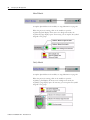
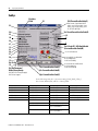
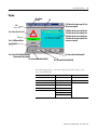
Digital Input Module
To replace placeholders in the module, see Tag Substitution on page 30.
When the project is running, click on the module to open the 04_DigInp
display. The module is not visible when it is in normal state. The module is
visible when it is in any abnormal state:
Publication RA-UM001B-EN-P - November 2010
32
Developing an HMI Application
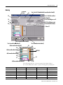
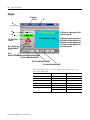
MotorN Module
To replace placeholders in the module, see Tag Substitution on page 30.
When the project is running, click on the module to open the
03_MotorN_small display. If the motor is in Single start mode, the
03_MotorN_large opens.
The motor symbol turns green to indicate the running state.
Publication RA-UM001B-EN-P - November 2010
Developing an HMI Application
33
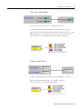
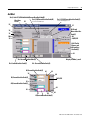
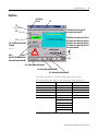
MotorR Module
To replace placeholders in the module, see Tag Substitution on page 30.
When the project is running, click on the module to open the
03_MotorR_small display. If the motor is in Single start mode, the
03_MotorR_large display opens. If necessary, you can replace the symbol
assigned to the group.
Publication RA-UM001B-EN-P - November 2010
34
Developing an HMI Application
MotorD Module
To replace placeholders in the module, see Tag Substitution on page 30.
When the project is running, click on the module to open the
03_MotorD_small display. If the motor is in Single start mode, the
03_MotorD_large display opens. If necessary, you can replace the symbol
assigned to the group.
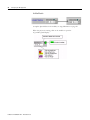
SubSys Module
To replace placeholders in the module, see Tag Substitution on page 30.
When the project is running, click on the module to open the
03_SubSys_small display. If the motor is in Single start mode, the
03_SubSys_large display opens. If necessary, you can replace the symbol
assigned to the group.
Publication RA-UM001B-EN-P - November 2010
Developing an HMI Application
35
Valve1, Valve2, Valve3 Module
To use Valve 2 or Valve 3, choose the appropriate module.
To replace placeholders in the module, see Tag Substitution on page 30.
When the project is running, click on the module to open the 03_Valve1_small
display. If the motor is in Single start mode, the 03_Valve1_large display
opens. If needed, you can replace the symbol assigned to the group.
AnaInp or AnaInpC Module
To replace placeholders in the module, see Tag Substitution on page 30.
When the project is running, click on the module to open the
05_AnaInp_small or 05_AnaInpC-small display.
Publication RA-UM001B-EN-P - November 2010
36
Developing an HMI Application
ActMod Module
To replace placeholders in the module, see Tag Substitution on page 30.
When the project is running, click on the module to open the
05_ActMod_small display.
Publication RA-UM001B-EN-P - November 2010
Developing an HMI Application
37
PID Module
To replace placeholders in the module, see Tag Substitution on page 30.
Click on the touch zone to open the 06_PIDMod display. You can find a
description of this faceplate in the operation description of the display.
Publication RA-UM001B-EN-P - November 2010
38
Developing an HMI Application
Control Group Module
Change the caption of the button from GRP to the AC Group Number of the
module (the H123 placeholder, for example, E51).
To replace placeholders in the module, see Tag Substitution on page 30.
The display is based on the assumption that a Control Group is always named
_H123_H456_H78 where H123 is the HAC Group Number, 456 is the AC
Asset Unit and H78 is the AC Component (for example, E51_000_00). If
needed, you can replace the name with a name of your choice.
When the project is running, click the button to open the 11_CtrlGrp display.
Publication RA-UM001B-EN-P - November 2010
Developing an HMI Application
39
System Group Module
Change the caption of the button from GRP to the AC Group Number of the
module (the H123 placeholder, for example, E50).
To replace placeholders in the module, see Tag Substitution on page 30.
The display is based on the assumption that a System Group is always named
H123_H456_H78. Where H123 is the HAC Group Number, H456 is the AC
Asset Unit and H78 is the AC Component (for example, E50_000_000). If
needed, you can replace the name with a name of your choice.
When the project is running, click the button to open the 11_SysGrp display.
Publication RA-UM001B-EN-P - November 2010
40
Developing an HMI Application
Creating Equipment
There are some preconfigured pieces of equipment, which can be dragged to
the user display.
Each piece of equipment is composed of several objects.
To replace placeholders in the equipment, see Tag Substitution on page 30.
Some pieces of equipment may not require all of the substitutions listed in the
procedure. For example, the belt conveyor, above, only requires that the H123
and H456 substitutions are made.
Publication RA-UM001B-EN-P - November 2010
Developing an HMI Application
Modifying Graphic Objects
When you are using template graphics, do not modify the whole template to
change the shape or size of individual objects. This distorts fonts and other
objects in the graphic. Instead, only modify that object which needs to be
changed. See the example below for further explanation.
Selection Buttons for
Machine Groups (MaGrp)
There are many ways to generate selection buttons or switches. This section
describes how to add template buttons.
41
Change the caption of the button as needed.
Use the Tag Substitution procedure on page 30 to replace the following
placeholders.
Placeholder
Replace with
For example
_TOPIC_
The appropriate shortcut name
E50_V16
MaGrp_
The appropriate Machine Group name
E51_000_02
Publication RA-UM001B-EN-P - November 2010
42
Developing an HMI Application
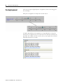
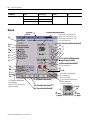
System Display
The system display is used for diagnostic purposes and is just an example. It
could be a base for creating system displays applying to the plant application.
• Server diagnostic for each HMI-, Data Server and FactoryTalk directory
• RSLinx Enterprise Diagnostic Counter for each shortcut
• System messages of each controller
Publication RA-UM001B-EN-P - November 2010
Developing an HMI Application
43
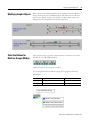
Communication
Supervision
The heartbeat mechanism is used to check if the FactoryTalk View SE Data
Server is still alive. The HMI tag Heartbeat reads a pulse from the
ControlLogix software. The derived tag function HeartbeatFct writes the
status of the Heartbeat tag to the derived tag HeartbeatRet. The
ControlLogix software monitors this tag for timeouts and generates an alarm.
Publication RA-UM001B-EN-P - November 2010
44
Developing an HMI Application
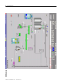
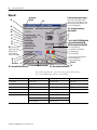
Diagnostic
The ControlLogix software provides a tag indication for proper Network
Communication {[E50_V16]NetworkOK.0}. On Network error, the module
color changes to RED. Clicking on the module opens a Network diagnostic
display for this network.
Clicking on the two processor modules next to DNB module in the chassis
also opens two different Controller Diagnostic faceplates. One is RSLinx
software-based and the other one is L_CPU_AOI instruction-based. Both are
provided as a user reference.
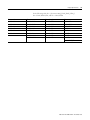
Network Screen
There is a direct reference tag used to indicate whether a module it is
healthy/available or not. For further information about the module status bits,
please refer to the RSLogix 5000 Online Help and search under
Module-Defined Data Types for the desired module.
The large red X indicates that modules are unhealthy/not available.
Publication RA-UM001B-EN-P - November 2010
Developing an HMI Application
Trends
45
To use the trend ActiveX in FactoryTalk View SE, the trend data must be
configured in an Data Log Model in order to be visible in the displays. The
following tags must be added to the Data Log Model named ‘day’.
Display Template
Tag
AnaInp
H123\H456\H78\Val\PV
ActMod
H123\H456\H78\Val\PV
PidMod
H123\H456\H78\Val\PV
H123\H456\H78\Val\BCZ
H123\H456\H78\Val\CV
H123\H456\H78\Val\SPZ
Trend Displays
Any other tag as required
Publication RA-UM001B-EN-P - November 2010
46
Developing an HMI Application
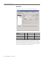
Alarming
When the files from the Data Retrieval Tool (HMITag-[shortcut name].csv
and Alarms-[shortcut name].csv) have been imported, all the necessary alarm
configuration of the Tags from the Data Retrieval Tool is complete.
The imported alarms use the configuration in the Alarm Setup (double-click
the Alarm Setup) on the User Msgs tab.
Where,
•
•
•
•
•
•
Alarm date = 11d
Alarm time = 8t
Alarm Label = 10l
Alarm tag name = 40n
Alarm threshold value = 15v
Alarm units = 10u
Additional alarms must be configured accordingly.
Publication RA-UM001B-EN-P - November 2010
Developing an HMI Application
47
Digital Alarms
The standard configuration is defined as follows.
These settings can be modified according to the project application’s
requirements.
Publication RA-UM001B-EN-P - November 2010
48
Developing an HMI Application
Analog Alarm
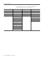
The standard configuration uses four thresholds, defined as follows.
Threshold
Severity
Alarm Label
Direction
H123\H456\H78\Set\NV
1
H123-H456.H78:NA
Decreasing
H123\H456\H78\Set\LV
2
H123-H456.H78:LA
Decreasing
H123\H456\H78\Set\HV
2
H123-H456.H78:HA
Increasing
H123\H456\H78\Set\MV
1
H123-H456.H78:MA
Increasing
An alarm is not clearable until the device in alarm is back in a normal state.
The analog alarm value H123\H456\H78\Val\PVA stays at the alarm level,
until it has been acknowledged by the operator with the display acknowledge
button. An analog alarm counts as 1 alarm, even if two messages are visible in
the alarm list (for example, High-alarm and Max-alarm).
Publication RA-UM001B-EN-P - November 2010
Developing an HMI Application
49
Derived Tags - Alarming
The last step to configure the alarm is to create a derived tag file named
‘Alarming’. One file from the HDRS Data Retrieval Tool
(HMIDerivedTags-[shortcut name].csv could be used to copy and paste
Derived Tag Name and Expression into this file.
Publication RA-UM001B-EN-P - November 2010
50
Developing an HMI Application
Notes:
Publication RA-UM001B-EN-P - November 2010
Chapter
2
Runtime Operation
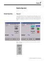
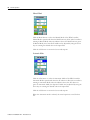
Common Operations
Singlestart
Click the Manual/Auto button to switch between the small and large versions
of the display. The large version of the display includes the Singlestart buttons.
This Manual/Auto button is enabled only if the user is logged in as Electrician,
Engineer, or Administrator. Singlestart mode is indicated when the button is
cyan.
When the Singlestart mode is terminated by the Group module, the buttons
are not accessible.
51
Publication RA-UM001B-EN-P - November 2010
52
Runtime Operation
Acknowledge
If an object has an unacknowledged alarm, that object’s Acknowledge button
is blue. Clicking this button sends an ACK command to the controller and
acknowledges alarms for the object or the group in the alarm function.
Local Mode
Clicking the Local button enables the Local mode of the object. This means
that the object can be controlled at the motor by the Start and Stop buttons.
The Local Mode is active when the button is white. This function can be
switched on or off by the Group module.
Publication RA-UM001B-EN-P - November 2010
Runtime Operation
53
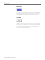
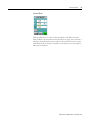
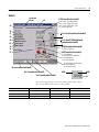
Info Function
Clicking the Info button brings up another popup faceplate to enter user
information for the device
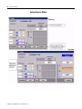
Value Input
The value input is used for the Analog and ActMod modules. Use the arrow
buttons to change the values within the range indicated. Each click changes the
value by 1% of the range in either direction.
You can also change the value by entering the desired number within the input
field.
Publication RA-UM001B-EN-P - November 2010
54
Runtime Operation
Analog/Actuator Module
Publication RA-UM001B-EN-P - November 2010
Runtime Operation
55
When the replacement value is active, the Replacement button and bar graph
are orange.
PID Module
Publication RA-UM001B-EN-P - November 2010
56
Runtime Operation
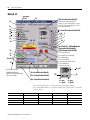
Manual Mode
Click the MAN button to select the Manual Mode of the PID Controller.
Manual Mode is preselected when the MAN button is yellow. The Controller is
running in Manual Mode when the indicator above the MAN button is green.
In Manual Mode, the Controlled Variable can be adjusted by using the arrow
keys or entering the desired value in the input field.
Click the ACC button to restore the last stored setpoint.
Automatic Mode
Click the AUT button to select the Automatic Mode of the PID Controller.
Automatic Mode is preselected when the AUT button is blue. The controller is
running in Automatic Mode when the indicator above the AUT button is
green. In Automatic Mode, the Setpoint Variable can be adjusted by using the
arrow keys or entering the desired value in the input field.
Click the ACC button to restore the last stored setpoint.
When the Automatic mode is selected, the actual setpoint is stored for later
use.
Publication RA-UM001B-EN-P - November 2010
Runtime Operation
57
External Mode
Click the EXT button to select the External Mode of the PID Controller.
External Mode is preselected when the EXT button is green. The controller is
running in External Mode when the indicator above the EXT button is green.
In External Mode, the Setpoint Variable is controlled by an external setpoint
and cannot be adjusted.
Publication RA-UM001B-EN-P - November 2010
Runtime Operation
E50 Example
58
Publication RA-UM001B-EN-P - November 2010
Appendix
A
Display Tag Reference
This appendix describes the tag references in the MMCL display templates.
59
Display Template
Page
Control Group
60
MotorN
62
MotorN_E3
63
MotorR
64
MotorR_E3
66
MotorD
68
MotorD_E3
70
SubSys
72
Analog Enhanced
73
Analog
75
ActMod
77
PIDMod
79
Valve1
81
Valve2
83
DigInp
85
DigInp2
86
DigPulse
87
Local Message Display
88
CommErr
88
Value Input
89
SysGrp
90
Publication RA-UM001B-EN-P - November 2010
60
Display Tag Reference
Control Group
52
54
22
2/CurrentUserHasCode(B)
35, 36
4/32/CurrentuserHasCode(B)
22
33
38
28
16/34/CurrentUserHasCode(D)
15/26/CurrentUserHasCode(B)
18/42/62
1/CurrentUserHasCode(B)
7/CurrentUserHasCode(B)
17/60/CurrentUserHasCode(B)
25
23
30/29
24
31
100–131
40
41
37
21
50
5/27/CurrentUserHasCode(B)
Set 3, Ack #2*/#2AlmUnAckd/
CurrentUserHasCode(B)
Vis If (#2\AlmUnAckd)=0) and
((#1_#2_#3_#4_C.Sta.W or
#1_#2_#3_#4_C.Sta.F)=1) then 1 else 0
25 or 28 or 23 or 29
Vis: CurrentUserHasCode(C)
28
55/23/61
Vis: CurrentUserHasCode(B)
In the following table, #1 = [shortcut name]_H123_H456_H78_C,
#2 = H123\H456\H78, and #3 = [Shortcut name]Global.
Commands
Status
Status (cont.)
MSGText
MSGText (cont.)
1=#1.Cmd.0
21=#1.Sta.ACT
37=#1.Sta.MAT
100=#2\MSGText\IntlStart00
116=#2\MSGText\IntlStop00
2=#1.Cmd.1
22=#1.Sta.RRQ
38=#1.Sta.CK
101=#2\MSGText\IntlStart01
117=#2\MSGText\IntlStop01
3=#1.Cmd.3
23=#1.Sta.STA
102=#2\MSGText\IntlStart02
118=#2\MSGText\IntlStop02
4=#1.Cmd.4
24=#1.Sta.STP
40=#1.Sta.PP
103=#2\MSGText\IntlStart03
119=#2\MSGText\IntlStop03
5=#1.Cmd.6
25=#1.Sta.WAI
120=#2\MSGText\IntlStop04
26=#1.Sta.RSB
41=#2\COMText\M
sgDisp00…15
104=#2\MSGText\IntlStart04
7=#1.Cmd.8
105=#2\MSGText\IntlStart05
121=#2\MSGText\IntlStop05
15=#1.Cmd.2
27=#1.Sta.IMS
122=#2\MSGText\IntlStop06
16=#1.Cmd.7
28=#1.Sta.STU
42=#1.Sta.GrpIdent 106=#2\MSGText\IntlStart06
ify
107=#2\MSGText\IntlStart07
Publication RA-UM001B-EN-P - November 2010
123=#2\MSGText\IntlStop07
Display Tag Reference
Commands
Status
Status (cont.)
MSGText
MSGText (cont.)
17=#1.Cmd.9
29=#1.Sta.RDY
Values
108=#2\MSGText\IntlStart08
124=#2\MSGText\ImmStop00
30=#1.Sta.RUN
50=#1.Val.RT
109=#2\MSGText\IntlStart09
125=#2\MSGText\ImmStop01
31=#1.Sta.STD
51=#1.Val.INR
110=#2\MSGText\IntlStart10
126=#2\MSGText\ImmStop02
32=#1.Sta.REU
52=#2\Name
111=#2\MSGText\IntlStart11
127=#2\MSGText\ImmStop03
33=#1.Sta.OCC
54=#2\Text
112=#2\MSGText\IntlStart12
128=#2\MSGText\ImmStop04
34=#1.Sta.RIR
55=#1.Val.STA_RT
113=#2\MSGText\IntlStart13
129=#2\MSGText\ImmStop05
35=#1.Sta.W
60=#1.Par.AllowSt
artPause
114=#2\MSGText\IntlStart14
130=#2\MSGText\ImmStop06
36=#1.Sta.F
61=#1.Par.Starting
TimeOutPreset
115=#2\MSGText\IntlStart15
131=#2\MSGText\ImmStop07
18=#1.Cmd.10
61
62=#3.Par.EnGrpIde
ntify
Publication RA-UM001B-EN-P - November 2010
62
Display Tag Reference
MotorN
52
5/34/CurrentUserHasCode(C)
24 yellow,
25 red
Alarm remark: Single Mode ON/OFF
MotorN_small: Display MotorN_large
MotorN_large: Display MotorN_small
Vis: #1.Par.DisableSingle
54
28
29
Vis: 34 and CurrentUser
HasCode(C)
2
1
30
22
26
27
Set 3, Ack #3\*/#2\AlmUnAck
/CurrentUserHasCode(B)
4/33/CurrentUserHasCode(B)
31
32
Vis: [Shortcut name]
Global HeavyStartup
AND (NOT #1.Par.
HeavyStartupIgn)
AND #1.Aux.Stopped
Vis: #1.Par.DisableLocal
#1.Sta.IntlkOK/#1.Sta.NbintlOK/
#1.Sta.IntlkBypActive
Vis.#1.Par.HasIntlObj
#1.Sta.PermOK/#1.Sta.NBPermOK
/#1.Sta.PermBypActive
Vis.#1.Par.HasPermObj
50
51
Vis: 55>0
Vis: CurrentUserHasCode(C) Vis: CurrentUserHasCode(B) Vis: CurrentUserHasCode(C)
35 or 23
35
In the following table, #1 = [shortcut name]_H123_H456_H78_C,
#2 = H123\H456\H78, and #3 = H123/H456.
Commands
Status
Status (cont.)
Values
1=#1.Cmd.0
20=#1.Sta.RP
28=#1.Sta.TAM
50=#1.Val.RT
2=#1.Cmd.1
21=#1.Sta.RU
29=#1.Sta.RAM
51=#1.Val.DC
3=#1.Cmd.3
22=#1.Sta.RM
30=#1.Sta.SAM
52=#2\Name
4=#1.Cmd.4
23=#1.Sta.WAI
31=#1.Sta.IDS
54=#2\Text
5=#1.Cmd.5
24=#1.Sta.W
32=#1.Sta.IDP
55=#1.Val.RST_RT
25=#1.Sta.F
33=#1.Sta.REU
26=#1.Sta.UAM
34=#1.Sta.REG
27=#1.Sta.KAM
35=#1.Sta.STU
Publication RA-UM001B-EN-P - November 2010
Display Tag Reference
63
MotorN_E3
24 yellow,
25 red
5/34/CurrentUserHasCode(C)
Alarm remark: Single Mode ON/OFF
MotorN_E3_small: Display
MotorN_E3_large
MotorN_E3_large: Display
54
52
Vis: 34 and
CurrentUserHasCode (C)
28
29
2
1
22
30
26
27
31
32
Set 3, Ack #4\*/#2\AlmUnAckd/
CurrentUserHasCode(B)
Vis: {Shortcut
name}Global
HeavyStartup
4/33/CurrentUserHasCode(B)
80
81
82
AND [NOT
#1.Par.HeavyStartupIgn)
AND#1.Aux.Stopped
Vis: #1.Par.DisableLocal
#1.Sta.IntlkOK/#1.Sta.NBIntlkOK/
#1.Sta.IntlkbypActive
Vis: #1.Par.HasIntlkObj
83
#1.Sta.PermOK/#1.Sta.NBPermOK/
#1.Sta.PermbypActive
Vis: #1.Par.HasPermObj
50
51
55
Vis: CurrentUserhasCode(C)
Vis: CurrentUserhasCode(C)
35 35 or 23
Vis: CurrentUserhasCode(B)
In the following table, #1 = [shortcut name]_H123_H456_H78_C,
#2 = H123\H456\H78, #3 = [shortcut name]_H123_H456_H78_e3,
and #4 = H123/H456.
Commands
Status
Status (cont.)
Values
E3
1=#1.Cmd.0
20=#1.Sta.RP
28=#1.Sta.TAM
50=#1.Val.RT
80=#3.DeviceStatus.1
2=#1.Cmd.1
21=#1.Sta.RU
29=#1.Sta.RAM
51=#1.Val.DC
81=#3.TripStatus
3=#1.Cmd.3
22=#1.Sta.RM
30=#1.Sta.SAM
52=#2\Name
82=#3.AverageCurrent
4=#1.Cmd.4
23=#1.Sta.WAI
31=#1.Sta.IDS
54=#2\Text
83=#3.ThermUtilized
5=#1.Cmd.5
24=#1.Sta.W
32=#1.Sta.IDP
55 = #1.Val.RST_RT
Publication RA-UM001B-EN-P - November 2010
64
Display Tag Reference
Commands
Status
Status (cont.)
25=#1.Sta.F
33=#1.Sta.REU
26=#1.Sta.UAM
34=#1.Sta.REG
27=#1.Sta.KAM
35=#1.Sta.STU
Values
E3
MotorR
24 yellow, 55
25 red
5/34/CurrentUserHasCode(C)
53
Vis: 34 and CurrentUserHasCode(C)
28
29
30
26
27
31
32
6
57
7
58
1
Vis: #1.Par.DisableLocal
35
35 or 23
51
50
52
Vis: 59>0
59
AND {NOT #1.Par.HeavyStaturIgn)
AND#1.AuxStopped
56
Set 3, Ack #3\*/#2\AlmUnAckd/
CurrentUserHasCode(B)
4/33/CurrentUserHasCode(B)
50
Vis:{Shortcut name}Global
HeavyStartup:
Alarm remark: Single Mode ON/OFF
MotorR_small: Display MotorR_large
MotorR_large: Display MotorR_small
Vis: #1.Par.DisableSingle
Vis: CurrentUserHasCode(C)
Vis: CurrentUserHasCode(C(1))
Vis: CurrentUserHasCode(B)
#1.Sta.IntlkOK/#1.Sta.NBIntlkOK/
#1.Sta.IntlkbypActive
Vis:#1.Par.HasIntlkObj
#1.Sta.PermOK/#1.Sta.NBPermOK/
#1.Sta.PermbypActive
Vis:#1.Par.HasPermObj
21 or 22
21
21
0 = gray
1 = green
Publication RA-UM001B-EN-P - November 2010
20
20
0 = gray
1 = green
Display Tag Reference
65
In the following table, #1 = [shortcut name]_H123_H456_H78_C,
#2 = H123\H456\H78, and #3 = H123/H456
Commands
Status
Status (cont.)
Values
1=#1.Cmd.0
20=#1.Sta.RXM
28=#1.Sta.TAM
50=#1.Val.RT
3=#1.Cmd.3
21=#1.Sta.RYM
29=#1.Sta.RAM
51=#1.Val.DCX
4=#1.Cmd.4
22=#1.Sta.RM
30=#1.Sta.SAM
52=#1.Val.DCY
5=#1.Cmd.5
23=#1.Sta.WAI
31=#1.Sta.IDS
53=#2\Name
6=#1.Cmd.1
24=#1.Sta.W
32=#1.Sta.IDP
55=#2\Text
7=#1.Cmd.2
25=#1.Sta.F
33=#1.Sta.REU
56=#2\XText
26=#1.Sta.UAM
34=#1.Sta.REG
57=#2\YText
27=#1.Sta.KAM
35=#1.Sta.STU
58=#2\0Text
59=#1.Val.RST_RT
Publication RA-UM001B-EN-P - November 2010
66
Display Tag Reference
MotorR_E3
24 yellow,
25 red
55
5/34 /CurrentUserHasCode(C)
53
Alarm remark: Single Mode ON/OFF
MotorR_E3_small: Display MotoR_E3_large
MotoR_E3_large: Display MotorR_E3_small
Vis: #1.Par.DisableSingle
28
29
30
26
27
31
32
Vis: 34 and CurrentUserHasCode(C)
56
6
57
7
58 1
80 81
Set 3, Ack #4\* /#2\AlmUnAckd
/CurrentUserHasCode(B)
4/33/CurrentUserHasCode(B)
50
51
52
Vis: 59>0
82
83
Vis: #1.Par.DisableLocal
35
35 or 23
#1.Sta.IntlkOK/#1.Sta.NBIntlkOK/
#1.Sta.IntlkbypActive
Vis:#1.Par.HasIntlkObj
#1.Sta.PermOK/#1.Sta.NBPermOK/
#1.Sta.PermbypActive
Vis:#1.Par.HasPermObj
59
21 or 22
Vis: [Shortcut name]
Global.HeavyStartup
Vis: CurrentUserHasCode(C)
AND (NOT #1.Par.HeavyStartupIgn)
AND #1.Aux.Stopped
Vis: CurrentUserHasCode(B)
21
20
21
0 = gray
1 = green
Vis: CurrentUserHasCode(C)
20
0 = gray
1 = green
In the following table, #1 = [shortcut name]_H123_H456_H78_C,
#2 = H123\H456\H78, #3 = [shortcut name]_H123_H456_H78_e3, and #4
= H123\H456.
Commands
Status
Status (cont.)
Values
E3
1=#1.Cmd.0
20=#1.Sta.RXM
28=#1.Sta.TAM
50=#1.Val.RT
80=#3.DeviceStatus.1
3=#1.Cmd.3
21=#1.Sta.RYM
29=#1.Sta.RAM
51=#1.Val.DCX
81=#3.TripStatus
4=#1.Cmd.4
22=#1.Sta.RM
30=#1.Sta.SAM
52=#1.Val.DCY
82=#3.AverageCurrent
5=#1.Cmd.5
23=#1.Sta.WAI
31=#1.Sta.IDS
53=#2\Name
83=#3.ThermUtilized
Publication RA-UM001B-EN-P - November 2010
Display Tag Reference
Commands
Status
Status (cont.)
Values
6=#1.Cmd.1
24=#1.Sta.W
32=#1.Sta.IDP
55=#2\Text
7=#1.Cmd.2
25=#1.Sta.F
33=#1.Sta.REU
56=#2\XText
26=#1.Sta.UAM
34=#1.Sta.REG
57=#2\YText
27=#1.Sta.KAM
35=#1.Sta.STU
58=#2\0Text
67
E3
59=#1.Val.RST_RT
Publication RA-UM001B-EN-P - November 2010
68
Display Tag Reference
MotorD
5/34 CurrentUserHasCode(C)
24 yellow,
25 red
55
53
Alarm remark: Single Mode ON/OFF
MotorD_small: Display MotorD_large
MotorD_large: Display MotorD_small
Vis: #1.Par.DisableSingle
Vis: 34 and CurrentUserHasCode(C)
56 6
28
29
57 7
30
26
58 1
27
31
32
36, 37
38, 39
40, 41
50
51
52
Vis: 59>0
59
Set 3, Ack #3\* /#2\AlmUnAckd
/CurrentUserHasCode(B)
4/33/CurrentUserHasCode(B)
Vis: #1.Par.DisableLocal
35
Vis: [Shortcut name]
Global.HeavyStartup
AND (NOT #1.Par.HeavyStartupIgn)
AND #1.Aux.Stopped
35 or 23
#1.Sta.IntlkOK/#1.Sta.NBIntlkOK/
#1.Sta.IntlkbypActive
Vis:#1.Par.HasIntlkObj
#1.Sta.PermOK/#1.Sta.NBPermOK/
#1.Sta.PermbypActive
Vis:#1.Par.HasPermObj
Vis: 39
Vis: 37
20 or 21
Vis: 38
Vis: 36
Vis: CurrentUserHasCode(C)
Vis: CurrentUserHasCode(B)
Vis: CurrentUserHasCode(C)
43
42
21
0 = gray
1 = green
20
0 = gray
1 = green
In the following table, #1 = [shortcut name]_H123_H456_H78_C,
#2 = H123\H456\H78 and #3 = H123/H456
Commands
Status
Status (cont.)
Status (cont.)
Values
1=#1.Cmd.0
20=#1.Sta.RXM
29=#1.Sta.RAM
37=#1.Sta.TYAM
50=#1.Val.RT
3=#1.Cmd.3
21=#1.Sta.RYM
30=#1.Sta.SAM
38=#1.Sta.XAM
51=#1.Val.DCX
4=#1.Cmd.4
23=#1.Sta.WAI
31=#1.Sta.IDS
39=#1.Sta.YAM
52=#1.Val.DCY
5=#1.Cmd.5
24=#1.Sta.W
32=#1.Sta.IDP
40=#1.Sta.ZXAM
53=#2\Name
6=#1.Cmd.1
25=#1.Sta.F
33=#1.Sta.REU
41=#1.Sta.ZYAM
55=#2\Text
7=#1.Cmd.2
26=#1.Sta.UAM
34=#1.Sta.REG
42=#1.Sta.ZX
56=#2\XText
Publication RA-UM001B-EN-P - November 2010
Display Tag Reference
Commands
Status
Status (cont.)
Status (cont.)
Values
27=#1.Sta.KAM
35=#1.Sta.STU
43=#1.Sta.ZY
57=#2\YText
28=#1.Sta.TAM
36=#1.Sta.TXAM
69
58=#2\0Text
59=#1.Val.RST_RT
Publication RA-UM001B-EN-P - November 2010
70
Display Tag Reference
MotorD_E3
24 yellow,
25 red
5/34/CurretnUserHasCode(C)
55
Alarm remark: Single Mode On/Off
MotorD_E3_small: Display MotorD_E3_large
MotorD_E3_large: Display MotorD_E3_small
Vis: #1.Par.DisableSingle
Vis: 34 and CurrentUserHasCode(C)
53
28
29
30
26
27
31
32
36, 37
38, 39
40, 41
80
81
82
83
50
51
52
Vis: 59>0
59
56
6
57
7
58
1
Set 3, Ack #4\*/#2/AlmUnAckd/
CurrentUserHasCode(B)
4/33/CurrentUserHasCode(B)
Vis: #1.Par.DisableLocal
35 or 23
35
#1.Sta.IntlkOK/#1.Sta.NBIntlkOK/
#1.Sta.IntlkbypActive
Vis:#1.Par.HasIntlkObj
#1.Sta.PermOK/#1.Sta.NBPermOK/
#1.Sta.PermbypActive
Vis:#1.Par.HasPermObj
Vis: 37
Vis:[Shortcutname]
Global.HeavyStartup AND
(NOT #1.Par.HeavyStartupIgn)
AND #1.Aux.Stopped
20 or 21
Vis: 39
Vis: CurrentUserHasCode(C)
Vis: CurrentUserHasCode(B)
Vis: CurrentUserHasCode(C)
Vis: 36
Vis: 38
42
43
21
0 = gray
1 = green
20
0 = gray
1 = green
In the following table, #1 = [shortcut name]_H123_H456_H78_C,
#2 = H123\H456\H78, #3=[Shortcut name]_H123_H456_H78_e3,
and #4 = H123/H456
Publication RA-UM001B-EN-P - November 2010
Display Tag Reference
Commands
Status
Status (cont.)
Values
E3
1=#1.Cmd.0
20=#1.Sta.RXM
32=#1.Sta.IDP
50=#1.Val.RT
80=#3.DeviceStatus.1
3=#1.Cmd.3
21=#1.Sta.RYM
33=#1.Sta.REU
51=#1.Val.DCX
81=#3.TripStatus
4=#1.Cmd.4
23=#1.Sta.WAI
34=#1.Sta.REG
52=#1.Val.DCY
82=#3.AverageCurrent
5=#1.Cmd.5
24=#1.Sta.W
35=#1.Sta.STU
53=#2\Name
83=#3.ThermUtilized
6=#1.Cmd.1
25=#1.Sta.F
36=#1.Sta.TXAM
55=#2\Text
7=#1.Cmd.2
26=#1.Sta.UAM
37=#1.Sta.TYAM
56=#2\XText
27=#1.Sta.KAM
38=#1.Sta.XAM
57=#2\YText
28=#1.Sta.TAM
39=#1.Sta.YAM
58=#2\0Text
29=#1.Sta.RAM
40=#1.Sta.ZXAM
59=#1.Val.RST_RT
30=#1.Sta.SAM
41=#1.Sta.ZYAM
31=#1.Sta.IDS
71
42=#1.Sta.ZX
43=#1.Sta.ZY
Publication RA-UM001B-EN-P - November 2010
72
Display Tag Reference
SubSys
24 yellow,
25 red
5/34 /CurrentUserHasCode(C)
54
Alarm remark: Single Mode ON/OFF
SubSys_small: Display SubSys_large
SubSys_large: Display SubSys_small
Vis: #1.Par.DisableSingle
52
28
29
Vis: 34 and CurrentUserHasCode(C)
22
2
30
26
1
27
31
32
36
37
50
Set 3, Ack #3\* /#2\ AlmUnAckd
/CurrentUserHasCode(B)
Vis: #1.Par.DisableLocal
35
35 or 23
51
Vis: 55>0
55
Vis:[Shortcutname]
Global.HeavyStartup
Vis: CurrentUserHasCode(B)
AND (NOT #1.Par.HeavyStartupIgn)
AND #1.Aux.Stopped
Vis: CurrentUserHasCode(C)
Vis: CurrentUserHasCode(C)
#1.Sta.IntlkOK/#1.Sta.NBIntlkOK/
#1.Sta.IntlkbypActive
Vis:#1.Par.HasIntlkObj
#1.Sta.PermOK/#1.Sta.NBPermOK/
#1.Sta.PermbypActive
Vis:#1.Par.HasPermObj
In the following table, #1 = [shortcut name]_H123_H456_H78_C,
#2 = H123\H456\H78, and #3 = H123_H456
Commands
Status
Status (cont.)
Values
1=#1.Cmd.0
20=#1.Sta.RP
29=#1.Sta.RAM
50=#1.Val.RT
2=#1.Cmd.1
21=#1.Sta.RU
30=#1.Sta.SAM
51=#1.Val.DC
3=#1.Cmd.3
22=#1.Sta.RM
31=#1.Sta.IDS
52=#2\Name
4=#1.Cmd.4
23=#1.Sta.WAI
32=#1.Sta.IDP
54=#2\Text
5=#1.Cmd.5
24=#1.Sta.W
33=#1.Sta.REU
55=#1.Val.RST_RT
25=#1.Sta.F
34=#1.Sta.REG
26=#1.Sta.UAM
35=#1.Sta.STU
27=#1.Sta.KAM
36=#2\Sta\WAM_0…7
Vis: #1.Sta.WAM.0...7
28=#1.Sta.TAM
37=#2\Sta\CAM_0…7
Vis: #1.Sta.CAM.0...7
Publication RA-UM001B-EN-P - November 2010
Display Tag Reference
73
Analog Enhanced
24 yellow,
25 red
54
52
Set 3, Ack #2\*/#2\AlmUnAckd/CurrentUserHasCode(B)
Set 1, 21/41/CurrentUserHasCode(C)
Vis: #1.Par.EnBypass or 21
56/20 and CurrentUserHasCode(C)
32
33
38
57
40/59/39
60
46/Current
UserHasCode(C)
47/Current
UserHasCode(C)
48/Current
UserHasCode(C)
61
49/Current
UserHasCode(C)
Display AnaInpC_small
Vis: CurrentUserHasCode(B)
41/#1.Par.EnBypass and CurrentUserHasCode(C)
Vis: CurrentUserHasCode(C)
Vis: CurrentUserHasCode(C)
42/CurrentUserHasCode(C)
34
42
43
60
43/CurrentUserHasCode(C)
50/21/39
35
44/CurrentUserHasCode(C)
61
36
37
44
45
45/CurrentUserHasCode(C)
Publication RA-UM001B-EN-P - November 2010
74
Display Tag Reference
In the following table, #1 = [shortcut name]_H123_H456_H78_C,
#2 = H123\H456\H78, and #3=[shortcut name]_H123_H456_H78
Commands
Status (cont.)
Status (cont.)
Set (cont.)
Values
1=#1.Cmd.0
25=#1.Sta.F
34=#3.EMA
42=#1.Set.MV
50=#1.Val.PV
3=#1.Cmd.3
26=#1.Sta.KA
35=#3.EHA
43=#1.Set.HV
51=#1.Val.PVA
27=#1.Sta.MA
36=#3.ELA
44=#1.Set.LV
52=#2\Name
Status
28=#1.Sta.HA
37=#3.ENA
45=#1.Set.NV
54=#2\Text
20=#1.Sta.ESP
29=#1.Sta.LA
38=#1.Sta.ParErr
46=#1.Set.CMV
56=#1.Val.SPZ
21=#1.Sta.RZ
30=#1.Sta.NA
39=#1.Sta.NegGrad
47=#1.Set.CHV
57=#1.Val.PVY
22=#1.Sta.KM
31=#1.Sta.EnBypass
Set
48=#1.Set.CLV
58=#1.Val.PVZ
23=#1.Sta.ERR
32=#1.Sta.KAM
40=#1.Set.SP
49=#1.Set.CNV
24=#1.Sta.W
33=#1.Sta.ERRM
41=#1.Set.PVZ
Publication RA-UM001B-EN-P - November 2010
60=#1.Val.MZ
61=#1.Val.NZ
Display Tag Reference
75
Analog
24 yellow,
25 red
54
Set 3, Ack #2\*/AlmUnAckd/CurrentUserHasCode(B)
52
32
Set 1, 21/41/CurrentUser
HasCode(C)
Vis: #1.Par.EnBypass or 21
33
38
41/#1.Par.EnBypass and
CurrentUserHasCode(C)
Value: 57
Vis: CurrentUserHasCode(B)
Vis: CurrentUserHasCode(C)
42/CurrentUserHasCode(C)
34
42
Vis: CurrentUserHasCode(C)
43
60
43/CurrentUserHasCode(C)
50/21/39
35
44/CurrentUserHasCode(C)
36
37
61
45/CurrentUserHasCode(C)
45
44
In the following table, #1 = [shortcut name]_H123_H456_H78_C,
#2 = H123\H456\H78, and #3 = [shortcut name]_H123_H456_H78
Commands
Status (cont.)
Status (cont.)
Set
Values
1=#1.Cmd.0
25=#1.Sta.F
34=#3.EMA
40=#1.Set.SP
50=#1.Val.PV
3=#1.Cmd.3
26=#1.Sta.KA
35=#3.EHA
41=#1.Set.PVZ
51=#1.Val.PVA
27=#1.Sta.MA
36=#3.ELA
42=#1.Set.MV
52=#2\Name
Status
28=#1.Sta.HA
37=#3.ENA
43=#1.Set.HV
54=#2\Text
20=#1.Sta.ESP
29=#1.Sta.LA
38=#1.Sta.ParErr
44=#1.Set.LV
56=#1.Val.SPZ
21=#1.Sta.RZ
30=#1.Sta.NA
39=#1.Sta.NegGrad
45=#1.Set.NV
57=#1.Val.PVY
Publication RA-UM001B-EN-P - November 2010
76
Display Tag Reference
Commands
Status (cont.)
22=#1.Sta.KM
31=#1.Sta.EnBypass
58=#1.Val.PVZ
23=#1.Sta.ERR
32=#1.Sta.KAM
60=#1.Val.MZ
24=#1.Sta.W
33=#1.Sta.ERRM
61=#1.Val.NZ
Publication RA-UM001B-EN-P - November 2010
Status (cont.)
Set
Values
Display Tag Reference
77
ActMod
Set 3, Ack #2\*/#2\AlmUnAckd/CurrentUserHasCode(B)
Set 4, 38/CurrentUserHasCode(B)
24 yellow,
Vis: #1.Par.DisableLocal
54
25 red
Set 1, 21/41/CurrentUserHasCode(C)
Vis: #1.Par.EnBypass or 21
52
57
56/20 and
CurrentUserHas
Code(C)
60
40/56/101
32
33
100
39
41/#1.Par.En
Bypass and
CurrentUser
HasCode(C)
61
Display ActMod_small
Vis: CurrentUserHasCode(B)
Vis: CurrentUserHasCode(C)
Vis: CurrentUserHasCode(C)
42/CurrentUserHasCode(C)
34
42
43
60
43/CurrentUserHasCode(C)
50/21/101
35
44/CurrentUserHasCode(C)
61
36
44
45
37
45/CurrentUserHasCode(C)
Publication RA-UM001B-EN-P - November 2010
78
Display Tag Reference
In the following table, #1 = [shortcut name]_H123_H456_H78_C,
#2 = H123\H456\H78, and #3 = [shortcut name]_H123_H456_H78
Commands
Status (cont.)
Status (cont.)
Set
Values
1=#1.Cmd.0
24=#1.Sta.W
33=#1.Sta.ERRM
40=#1.Set.SP
50=#1.Val.PV
3=#1.Cmd.3
25=#1.Sta.F
34=#3.EMA
41=#1.Set.PVZ
51=#1.Val.PVA
4=#1.Cmd.4
26=#1.Sta.KA
35=#3.EHA
42=#1.Set.MV
52=#2\Name
27=#1.Sta.MA
36=#3.ELA
43=#1.Set.HV
54=#2\Text
28=#1.Sta.HA
37=#3.ENA
44=#1.Set.LV
56=#1.Val.SPZ
Status
20=#1.Sta.ESP
29=#1.Sta.LA
38=#1.Sta.REU
45=#1.Set.NV
57=#1.Val.PVY
21=#1.Sta.RZ
30=#1.Sta.NA
39=#1.Sta.ParErr
46=#1.Set.CMV
58=#1.Val.PVZ
22=#1.Sta.KM
31=#1.Sta.EnBypass
100=#1.Sta.DevErrM
47=#1.Set.CHV
60=#1.Val.MZ
23=#1.Sta.ERR
32=#1.Sta.KAM
101=#1.Sta.NegGrad
48=#1.Set.CLV
61=#1.Val.NZ
49=#1.Set.CNV
Publication RA-UM001B-EN-P - November 2010
Display Tag Reference
79
PIDMod
24 yellow,
25 red
53
Set 3, Ack #2\*/#2\AlmUnAckd /CurrentUserHasCode(B)
52
26
23
60
50
51
58
62
51
50
61
58
56
57
44
43
42
Vis: CurrentUserHasCode(B)
Vis: CurrentUserHasCode(C)
Color: #20
Set 7, Set 40
Vis 22 and CurrentUserHasCode(B)
Vis: CurrentUserHasCode(C)
Val 51
Vis 21 and 33 and CurrentUserHasCode(B)
Color 33
Set 40
Label 51
Val 50
Label 50
Val 58
Vis 34 and CurrentUserHasCode(B)
Vis: 33 AND 21 AND CurrentUserHasCode(B)
Color 34
If 40>61 Then 40 = 40 - ((60-61)/100)
Set 41
Else 40 = 61 Endif
Label 58
Vis: 34 AND CurrentUserHasCode(B)
If 41>0 Then 41 = 41 - 1 Else 41 = 0 Endif
Vis: 33 AND 21 AND
Set 5
Set 6
CurrentUserHasCode(B)
Set 41
Vis 32 and
Vis 31 and
CurrentUserHasCode(B) If 40<60 Then 40 = 40 + ((60-61)/100) Else 40 =
60 Endif
CurrentUserHasCode(B) Set 4, Set 40
Color 38
Vis: 34 AND CurrentUserHasCode(B)
Color 37
Vis 30 and
Ind 35
If 41<100 Then 41 = 41 + 1 Else 41 = 100 Endif
Ind 35
CurrentUserHasCode(B)
Color 36
Ind 33
Publication RA-UM001B-EN-P - November 2010
80
Display Tag Reference
In the following table, #1 = [shortcut name]_H123_H456_H78_C,
#2 = H123\H456\H78, and #3 = AC numbers for CV.
Commands
Status
Set
Values
3=#1.Cmd.3
20=#1.Sta.E
40=#1.Set.SP
50=#1.Val.PV
4=#1.Cmd.1
21=#1.Sta.ESP
41=#1.Set.CVS
51=#1.Val.SPZ
5=#1.Cmd.0
22=#1.Sta.EAC
42=#1.Set.CP
52=#2\NamePID
6=#1.Cmd.2
23=#1.Sta.ERR
43=#1.Set.CI
53=#2\Text
7=#1.Cmd.4
24=#1.Sta.W
44=#1.Set.CD
56=#1.Val.ACC
25=#1.Sta.F
57=#1.Val.CE
26=#1.Sta.CDA
58=#1.Val.CV
27=#1.Sta.CFF
60= #1.Par.MZ
28=#1.Sta.RZ
61= #1.Par.NZ
30=#1.Sta.ECC
62=#2\Val\BCZ
31=#1.Sta.ECU
32=#1.Sta.ECX
33=#1.Sta.RCC
34=#1.Sta.RCU
35=#1.Sta.RCX
36=#1.Sta.BCC
37=#1.Sta.BCU
38=#1.Sta.BCX
Publication RA-UM001B-EN-P - November 2010
Display Tag Reference
81
Valve1
25 yellow,
26 red
5/37/CurrentUserHasCode(C)
54
Alarm remark: Single Mode ON/OFF
Valve1_small: Display Valve1_large
Valve1_large: Display Valve1_small
Vis: #1.Par.DisableSingle
52
31
27
Vis: 37 and CurrentUserHasCode(C)
2
Set 3, Ack #3\*/#2\AlmUnAckd/
CurrentUserHasCode(B)
1
4/36/CurrentUserHasCode(B)
28
34
35
32
33
51
Vis: #1.Par.DisableLocal
6/45/CurrentUserHasCode(C)
38 or 24
38
Vis: #1.Par.EnBypass
#1.Sta.IntlkOK/#1.Sta.NBIntlkOK/
#1.Sta.IntlkbypActive
Vis:#1.Par.HasIntlkObj
#1.Sta.PermOK/#1.Sta.NBPermOK/
#1.Sta.PermbypActive
Vis:#1.Par.HasPermObj
Vis: CurrentUserHasCode(C)
Vis: CurrentUserHasCode(B)
43/45
44/45
Vis: CurrentUserHasCode(C)
22
In the following table, #1 = [shortcut name]_H123_H456_H78_C,
#2 = H123\H456\H78, and #3 = H123_H456
Commands
Status
Status (cont.)
Values
1=#1.Cmd.0
20=#1.Sta.RPX
33=#1\.Sta.ZYAM
51=#1.Val.DCX
2=#1.Cmd.1
21=#1.Sta.RUX
34=#1.Sta.IDS
52=#2\Name
3=#1.Cmd.3
22=#1.Sta.RXM
35=#1.Sta.IDP
54=#2\Text
Publication RA-UM001B-EN-P - November 2010
82
Display Tag Reference
Commands
Status
Status (cont.)
4=#1.Cmd.4
23=#1.Sta.KM
36=#1.Sta.REU
5=#1.Cmd.5
24=#1.Sta.WAI
37=#1.Sta.REG
6=#1.Cmd.6
25=#1.Sta.W
38=#1.Sta.STU
26=#1.Sta.F
39=#1.Sta.SA
27=#1.Sta.UAM
40=#1.Sta.KA
28=#1.Sta.KAM
41=#1.Sta.ZXA
29=#1.Sta.TAM
42=#1.Sta.ZYA
30=#1.Sta.RAM
43=#1.Sta.ZX
31=#1.Sta.SAM
44=#1.Sta.ZY
32=#1.Sta.ZXAM
45=#1.Sta.BA
Publication RA-UM001B-EN-P - November 2010
Values
Display Tag Reference
83
Valve2
28 yellow,
29 red
5/40 /CurrentUserHasCode(C)
54
Alarm remark: Single Mode ON/OFF
Valve2_small: Display Valve2_large
Valve2_large: Display Valve2_small
Vis: #1:Par.DisableSingle
52
Vis: 40 and CurrentUserHasCode(C)
34
30
56
6
57
7
58
31
37
38
35
36
51
55
1
Set 3, Ack #3\*/#2\AlmUnAckd /
CurrentUserHasCode(B)
4/39/CurrentUserHasCode(B)
Vis: #1.Par.DisableLocal
8/48/CurrentUserHasCode(C)
Vis: #1.Par.EnBypass
#1.Sta.IntlkOK/#1.Sta.NBIntlkOK/
#1.Sta.IntlkbypActive
Vis:#1.Par.HasIntlkObj
Vis: CurrentUserHasCode(C)
41
Vis: CurrentUserHasCode(B)
41 or 27
#1.Sta.PermOK/#1.Sta.NBPermOK/
#1.Sta.PermbypActive
Vis:#1.Par.HasPermObj
Vis: CurrentUserHasCode(C)
46/48
47/48
24 or 25
25
24
In the following table, #1 = [shortcut name]_H123_H456_H78_C,
#2 = H123\H456\H78, and #3=H123/H456
Commands
Status
Status (cont.)
Status (cont.)
1=#1.Cmd.0
20=#1.Sta.RPX
32=#1.Sta.TAM
44=#1.Sta.ZXA
3=#1.Cmd.3
21=#1.Sta.RPY
33=#1.Sta.RAM
45=#1.Sta.ZYA
4=#1.Cmd.4
22=#1.Sta.RUX
34=#1.Sta.SAM
46=#1.Sta.ZX
5=#1.Cmd.5
23=#1.Sta.RUY
35=#1.Sta.ZXAM
47=#1.Sta.ZY
6=#1.Cmd.1
24=#1.Sta.RXM
36=#1\.Sta.ZYAM
48=#1.Sta.BA
7=#1.Cmd.2
25=#1.Sta.RYM
37=#1.Sta.IDS
Values
8=#1.Cmd.6
26=#1.Sta.KM
38=#1.Sta.IDP
51=#1.Val.DCX
Publication RA-UM001B-EN-P - November 2010
84
Display Tag Reference
Commands
Status
Status (cont.)
Status (cont.)
27=#1.Sta.WAI
39=#1.Sta.REU
52=#2\Name
28=#1.Sta.W
40=#1.Sta.REG
54=#2\Text
29=#1.Sta.F
41=#1.Sta.STU
55=#1.Val.DCX
30=#1.Sta.UAM
42=#1.Sta.SA
56=#2\XText
31=#1.Sta.KAM
43=#1.Sta.KA
57=#2\YText
58=#2\0Text
Publication RA-UM001B-EN-P - November 2010
Display Tag Reference
85
DigInp
23 yellow,
24 red
54
If 20 then local message #1 else
local message #0
53
(16 characters)
If 20 then local message #2 else
If 25 then local message #3 else
If 26 then local message #4 else
If 24 then local message #5 else
local message #0
Vis: 20 or 25 or 26 or 27
21
Set 1, 20/CurrentUser
HasCode(C)
Vis: 10
Set 3, Ack #2\*/#2\AlmUnAckd
/CurrentUserHasCode(B)
Vis: CurrentUserHasCode(C)
Vis: CurrentUserHasCode(C)
Vis: CurrentUserHasCode(B)
In the following table, #1 = [shortcut name]_H123_H456_H78_C, and
#2 = H123\H456\H78
Commands
Status
Values
1=#1.Cmd.0
20=#1.Sta.BA
53=#2\Name
21=#1.Sta.RB
54=#2\Text
3=#1.Cmd.3
22=#1.Sta.KM
Parameters
23=#1.Sta.W
10=#1.Par.EnBypass
24=#1.Sta.F
25=#1.Sta.KA
26=#1.Sta.WA
27=#1.Sta.MA
Publication RA-UM001B-EN-P - November 2010
86
Display Tag Reference
DigInp2
23 yellow,
24 red
54
53
(16 characters)
28
if 20 then local message #1 else
local message #0
29
If 20 then local message #2 else
If 25 then local message #3 else
If 26 then local message #4 else
If 27 then local message #5 else
local message #0
Vis: 20 or 25 or
26 or 27
Set 1, 20/Current
UserHasCode(C)
Vis: 10
Set 3,
Ack #2\*/#2\AlmUnAckd /CurrentUserHasCode(B)
Vis: CurrentUserHasCode(C)
Vis: CurrentUserHasCode(B)
Vis: CurrentUserHasCode(C)
In the following table, #1 = [shortcut name]_H123_H456_H78_C, and
#2 = H123\H456\H78
Commands
Status
Status (cont.)
1=#1.Cmd.0
20=#1.Sta.BA
27=#1.Sta.MA
3=#1.Cmd.3
Publication RA-UM001B-EN-P - November 2010
21=#1.Sta.RB
28=#1.Sta.WM
22=#1.Sta.KM
29=#1.Sta.FM
Parameters
23=#1.Sta.W
10=#1.Par.EnBypass
24=#1.Sta.F
Values
25=#1.Sta.KA
53=#2\Name
26=#1.Sta.WA
54=#2\Text
Display Tag Reference
87
DigPulse
23 yellow,
24 red
54
53
(16 characters)
If 20 then local message #1
else local message #0
55
If 20 then local message #2 else
If 25 then local message #3 else
If 26 then local message #4 else
If 27 then local message #5 else
local message #0
21
Set 1, 20/CurrentUserHas
Code(C)
Vis: 10
30
29
26 or 27
Set 3,
Ack #2\*/#2\AlmUnAckd
/CurrentUserHasCode(B)
28
Vis: CurrentUserHasCode(C)
Vis: CurrentUserHasCode(B)
Vis: CurrentUserHasCode(C)
In the following table, #1 = [shortcut name]_H123_H456_H78_C,
#2 = H123\H456\H78, and #3 = [shortcut name]_H123_H456_H78
Commands
Status
Values
1=#1.Cmd.0
20=#1.Sta.BA
53=#2\Name
3=#1.Cmd.3
21=#1.Sta.RB
54=#2\Text
22=#1.Sta.KM
Parameters
23=#1.Sta.W
Inputs
10=#1.Par.EnBypass
24=#1.Sta.F
55=#3.VSD
25=#1.Sta.KA
26=#1.Sta.WA
27=#1.Sta.MA
28=#1.Sta.Acc
29=#1.Sta.Run
30=#1.Sta.Dec
Publication RA-UM001B-EN-P - November 2010
88
Display Tag Reference
Local Message Display
CommErr
&Set CommERR 0 Abort
Publication RA-UM001B-EN-P - November 2010
Display Tag Reference
89
Value Input
{#2\#3\#4\Name}
{#2\#3\#4\Set\#5}
#1_#2_#3_#4_C.Set.#5
#1_#2_#3_#4_C.Val.NZ
#1_#2_#3_#4_C.Val.MZ
If {#1_#2_#3_#4_C.Set.#5}<{#1_#2_#3_#4_C.Val.MZ} Then
{#1_#2_#3_#4_C.Set.#5} = {#1_#2_#3_#4_C.Set.#5} +
(({#1_#2_#3_#4_C.Val.MZ}-{#1_#2_#3_#4_C.Val.NZ})/100)
Else #1_#2_#3_#4_C.Set.#5 = {#1_#2_#3_#4_C.Val.MZ}
Endif
If {#1_#2_#3_#4_C.Set.#5}>{#1_#2_#3_#4_C.Val.NZ} Then
{#1_#2_#3_#4_C.Set.#5} = {#1_#2_#3_#4_C.Set.#5} (({#1_#2_#3_#4_C.Val.MZ}-{#1_#2_#3_#4_C.Val.NZ})/100) Else
{#1_#2_#3_#4_C.Set.#5} = {#1_#2_#3_#4_C.Val.NZ} Endif
Publication RA-UM001B-EN-P - November 2010
90
Display Tag Reference
SysGrp
23 yellow,
24 red
52
Set 4, 26/CurrentUserHasCode(B)
51
CurrentUserHasCode(C)/
Display 00_System /t[E50_V16]
20
25
22
5/21/CurrentUserHasCode(B)
30
31
32
33
34
35
36
37
38
50
Set 3, Ack H123\*/#2\AlmUnAckd /
CurrentUserHasCode(B)
6/CurrentUserHasCode(B)
40
41
42
Vis: CurrentUserHasCode(C)
Vis: CurrentUserHasCode(B)
In the following table, #1 = [shortcut name]_H123_H456_H78_C, and
#2 = H123\H456\H78
Commands
Status
Status (cont.)
Values
3=#1.Cmd.3
20=#1.Sta.BatteryFault
33=#2\MSGText\WA04
50=#1.Val.RT
4=#1.Cmd.4
21=#1.Sta.IMS
34=#2MSGText\FA00
51=#2\Name
5=#1.Cmd.6
22=#1.Sta.PowerDipFault
35=#2\ MSGText\FA01
52=#2\Text
6=#1.Cmd.2
23=#1.Sta.W
36=#2\MSGText\FA02
24=#1.Sta.F
37=#2\MSGText\FA03
25=#1.Sta.HMI_Timeout
38=#2\MSGText\FA04
26=#1.Sta.REU
30=#2\MSGText\WA01
40=#1.Sta.WGong
31=#2\MSGText\WA02
41=#1.Sta.FGong
32=#2\MSGText\WA03
42=#2.Sta.CLX_Heartbeat}
Publication RA-UM001B-EN-P - November 2010
Rockwell Automation Support
Rockwell Automation provides technical information on the Web to assist you in using its products.
At http://www.rockwellautomation.com/support/, you can find technical manuals, a knowledge base of FAQs, technical and
application notes, sample code and links to software service packs, and a MySupport feature that you can customize to make the
best use of these tools.
For an additional level of technical phone support for installation, configuration, and troubleshooting, we offer TechConnect
support programs. For more information, contact your local distributor or Rockwell Automation representative,
or visit http://www.rockwellautomation.com/support/.
Installation Assistance
If you experience a problem within the first 24 hours of installation, review the information that is contained in this manual.
You can contact Customer Support for initial help in getting your product up and running.
United States or Canada
1.440.646.3434
Outside United States or
Canada
Use the Worldwide Locator at http://www.rockwellautomation.com/support/americas/phone_en.html, or contact
your local Rockwell Automation representative.
New Product Satisfaction Return
Rockwell Automation tests all of its products to ensure that they are fully operational when shipped from the manufacturing facility.
However, if your product is not functioning and needs to be returned, follow these procedures.
United States
Contact your distributor. You must provide a Customer Support case number (call the phone number above to obtain
one) to your distributor to complete the return process.
Outside United States
Please contact your local Rockwell Automation representative for the return procedure.
Documentation Feedback
Your comments will help us serve your documentation needs better. If you have any suggestions on how to improve this document,
complete this form, publication RA-DU002, available at http://www.rockwellautomation.com/literature/.
Rockwell Otomasyon Ticaret A.Ş., Kar Plaza İş Merkezi E Blok Kat:6 34752 İçerenköy, İstanbul, Tel: +90 (216) 5698400
Publication RA-UM001B-EN-P - November 2010 16
Supersedes Publication RA-UM001A-EN-P - September 2007
Copyright © 2010 Rockwell Automation, Inc. All rights reserved. Printed in the U.S.A.