1
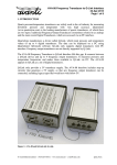
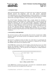
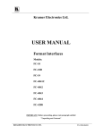
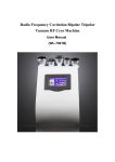
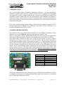
Digital Quartz Transducer Simulator (AVA-02-A)
06-JAN-2015
Page 1 of 6
1. INTRODUCTION
The Avanti Digital Quartz Transducer Simulator substitutes a pressure/temperature
transducer equipped with a two-wire serial I²C interface. It was designed to be compatible
with Quartzdyne's range of digital quartz pressure transducers and facilitates testing of data
acquisition systems without the need for real transducers. The simulator also features a
special error mode, which simulates erratic I²C behaviour. This is useful for checking how
well a data acquisition system recovers from a locked up I²C bus and whether it can detect
inconsistent data values.
In its latest implementation (model number AVA-02-A) the simulator supports the I²C
protocol enhancements introduced by Quartzdyne with ASIC V4.02 (and above). It is
backward compatible with earlier versions.
2. HARDWARE DESCRIPTION
The simulator consists of a small standalone PCB (circa 50 x 60mm), containing a microcontroller and a serial EEPROM, which are both connected to the I²C bus.
There are two rotary switches (labelled PF and TF) for setting pressure and temperature
values and a LED, which flashes whenever the simulator has been polled successfully.
Two jumper links (labelled A1 and A2) are provided for setting the device address,
allowing up to 4 devices on the same I²C bus. The address lines are fitted with pull-up
resistors and the jumpers make a connection to ground, i.e. a jumper inserted means the
address line is low and a jumper removed means the address line is high. The address lines
are also available externally via the 9-way D-type socket, so that alternatively the device
address can be coded through ground connections on the host-board. The jumper links
must be removed for this. The table below shows the pin-out of the D-type socket. The
pin-out is also printed on the bottom side of the PCB. Note that Quartzdyne transducer
cables that are terminated with a D-type plug have a different pin-out.
Pin-1
Pin-2
Pin-3
Pin-4
Pin-5
Pin-6
Pin-7
Pin-8
Pin-9
A1
SCL
GND
SDA
+VS (2.7V to 5.5V)
A2
GND
GND
GND
All external connections are over voltage and reverse voltage protected. However, in order
to minimise the possibility of damage through ESD, unnecessary touching of component
pins and PCB pads should be avoided.
© Avanti Elektronik Limited - (44) 01224 583132 - www.avanti.clara.net - [email protected]
dqdsim_15.doc
Digital Quartz Transducer Simulator (AVA-02-A)
06-JAN-2015
Page 2 of 6
3. I²C INTERFACE
With the introduction of their Digital ASIC in 2009 (V4.02), Quartzdyne made some
enhancements to the I²C protocol. These include a checksum as a 5th byte when reading
from the transducer, and the extension of the status/control register from a single byte to 4
bytes. These enhancements are backward compatible with earlier versions, i.e. a host
system designed for an earlier transducer version will still work with the latest version.
Since 2010, the Avanti Transducer Simulator also supports the enhanced I²C protocol of
V4.02 and later. Earlier simulators were based on Quartzdyne FPGA V3.02 and may be
upgraded on request. Likewise, a new simulator may still be purchased with the older
V3.02 firmware, should this be preferred (order as model AVA-02-F).
Old and new versions can be distinguished by their serial number. The old version serial
number contains digits only (e.g. SN: 0123) while the new version is suffixed with an 'A'
for ASIC (e.g. SN: 0123-A)
The Avanti Digital Quartz Transducer Simulator supports the following I²C commands.
For details refer to the Quartzdyne Digital Transducer Programming Manual.
- Query the pressure counter. This returns a 32-bit pressure reading plus a check byte.
Reading the check byte is optional. It may be used for validation of the pressure reading.
In case a mismatch is found, the pressure value and the check byte can be read again,
simply by continuing and reading 5 more bytes. When finished, the read access must be
terminated by issuing an I²C STOP.
- Query the temperature counter. This returns a 32-bit temperature reading plus an optional
check byte as above.
- Query the Version-ID. This returns a 32-bit version identifier plus an optional check byte
as above.
- Query the status register. Up to 4 status bytes plus a check byte may be read as above,
but in most applications only the information contained in the first status byte is of
relevance (state of the pressure/temperature counters and the EEPROM write protection
bit). The other 3 bytes are optional and have no function in the Avanti simulator, but
must be included if the check byte is to be verified.
- Write to control register. Up to 4 control bytes may be written, but as above, only the
first byte is of relevance in most applications. The first byte enables/disables the pressure
and temperature counters and locks/unlocks the EEPROM write access. The other 3
bytes may be written, but are simply ignored by the Avanti simulator.
- Read/Write the serial EEPROM. The EEPROM is an independent device that shares the
same I²C bus. The EEPROM is write protected by default and must be unlocked by
writing to the control register, if its contents is to be changed. The EEPROM contains
four redundant sets of coefficients at address locations 0...0xFF, 0x100...0x1FF,
0x200...0x2FF and 0x300...0x3FF.
© Avanti Elektronik Limited - (44) 01224 583132 - www.avanti.clara.net - [email protected]
dqdsim_15.doc
Digital Quartz Transducer Simulator (AVA-02-A)
06-JAN-2015
Page 3 of 6
The I²C bus was developed by Philips Semiconductors (now NXP) and its specification
can be downloaded from their web-site. In its standard version the I²C bus allows a
maximum clock/data frequency of 100kHz, i.e. minimum high and low times of clock and
data lines must be observed by the master. The I²C protocol also specifies a mechanism
called 'clock stretching', which allows slaves to slow down the bus to below 100kHz.
While in the actual Quartzdyne transducer the I²C interface is implemented in an FPGA or
ASIC (i.e. entirely in hardware), the Avanti simulator employs a micro-controller with bitlevel I²C support (i.e. a mixture of hardware and firmware). This means that the Avanti
simulator is slightly less forgiving with respect to I²C timing issues. In particular 'clock
stretching' must be recognised by the master if running at high speed. This happens
automatically if the host-micro uses a dedicated I²C port. However, if the I²C interface in
the host is 'bit-banged' using two ordinary port pins for SCL and SDA, the host firmware
should check explicitly for 'clock stretching'. This is quite simple to implement: It only
requires the host firmware to make sure the SCL line actually goes high whenever the SCL
pin is set high and, if necessary, to wait for this to happen before proceeding.
4. VALUES RETURNED
Pressure and temperature values can be set independently by means of the two rotary
switches. For positions 1...8 the returned value is the switch position multiplied by 10kHz,
i.e. 10...80kHz. In switch position 0 a ramp is generated, which is repeated every 10
minutes. The pressure ramp starts at 30kHz and ramps upwards at a rate of 1Hz per
second. The temperature ramp starts at 40kHz and ramps downwards at a rate of -1Hz per
second. In switch position 9 the simulator runs in error mode, which generates regular I²C
lockups and checksum errors (see paragraph 5 for details).
Switch
Position
1
2
3
4
5
6
7
8
9
0
PF
10000 Hz
20000 Hz
30000 Hz
40000 Hz
50000 Hz
60000 Hz
70000 Hz
80000 Hz
30000 Hz with
regular I²C errors
Ramp
30000...30600 Hz
at 1Hz/sec =>
Sawtooth edge
every 10 minutes
Raw-Pres
returned
0x005B05B1
0x00B60B61
0x01111111
0x016C16C1
0x01C71C72
0x02222222
0x027D27D4
0x02D82D84
0x01111111
Ramp
0x01111111...
0x01168720
TF
10000 Hz
20000 Hz
30000 Hz
40000 Hz
50000 Hz
60000 Hz
70000 Hz
80000 Hz
40000 Hz with
regular I²C errors
Ramp
40000...39400 Hz
at -1Hz/sec =>
Sawtooth edge
every 10 minutes
© Avanti Elektronik Limited - (44) 01224 583132 - www.avanti.clara.net - [email protected]
Raw-Temp
returned
0x005B05B1
0x00B60B61
0x01111111
0x016C16C1
0x01C71C72
0x02222222
0x027D27D4
0x02D82D84
0x016C16C1
Ramp
0x016C16C1..
.
0x0166A0B1
dqdsim_15.doc
Digital Quartz Transducer Simulator (AVA-02-A)
06-JAN-2015
Page 4 of 6
The simulator is shipped with coefficients pre-loaded in the EEPROM. These coefficients
were taken off a real transducer and therefore produce engineering values, which represent
a typical Quartzdyne transducer. Only the serial number and the calibration date were
modified to reflect the simulators serial number and date of manufacture. The following
table shows the psi and °C values obtained with these coefficients:
PF 10kHz 20kHz 30kHz 40kHz 50kHz 60kHz 70kHz 80kHz
TF
psi -5648.515 psi -252.348 psi 4842.551 psi 9711.851 psi 14431.22 psi 19076.35 psi 23722.88 psi
10kHz -11421.63
236.342 °C 236.342 °C 236.342 °C 236.342 °C 236.342 °C 236.342 °C 236.342 °C 236.342 °C
20kHz
30kHz
40kHz
50kHz
60kHz
70kHz
80kHz
-8745.46 psi
194.991 °C
-6871.39 psi
150.948 °C
-5689.32 psi
98.854 °C
-5089.159 psi
33.349 °C
-4960.809 psi
-50.927 °C
-5194.183 psi
-159.332 °C
-5679.18 psi
-297.226 °C
-3710.684 psi
194.991 °C
-2371.768 psi
150.948 °C
-1569.95 psi
98.854 °C
-1243.407 psi
33.349 °C
-1330.312 psi
-50.927 °C
-1768.852 psi
-159.332 °C
-2497.196 psi
-297.226 °C
1101.552 psi
194.991 °C
2000.479 psi
150.948 °C
2476.813 psi
98.854 °C
2562.94 psi
33.349 °C
2291.249 psi
-50.927 °C
1694.117 psi
-159.332 °C
803.938 psi
-297.226 °C
5728.189 psi
194.991 °C
6262.484 psi
150.948 °C
6459.496 psi
98.854 °C
6333.302 psi
33.349 °C
5897.976 psi
-50.927 °C
5167.578 psi
-159.332 °C
4156.19 psi
-297.226 °C
10206.17 psi
194.991 °C
10431.37 psi
150.948 °C
10386.63 psi
98.854 °C
10071.10 psi
33.349 °C
9483.968 psi
-50.927 °C
8624.385 psi
-159.332 °C
7491.532 psi
-297.226 °C
14572.43 psi
194.991 °C
14524.28 psi
150.948 °C
14266.73 psi
98.854 °C
13779.75 psi
33.349 °C
13043.32 psi
-50.927 °C
12037.38 psi
-159.332 °C
10741.93 psi
-297.226 °C
18863.92 psi
194.991 °C
18558.34 psi
150.948 °C
18108.34 psi
98.854 °C
17462.68 psi
33.349 °C
16570.13 psi
-50.927 °C
15379.43 psi
-159.332 °C
13839.35 psi
-297.226 °C
23117.58 psi
194.991 °C
22550.67 psi
150.948 °C
21919.97 psi
98.854 °C
21123.30 psi
33.349 °C
20058.50 psi
-50.927 °C
18623.38 psi
-159.332 °C
16715.77 psi
-297.226 °C
When queried for the Version-ID, the simulator returns the value 0x0D090403, which
reads as Quartzdyne Digital ASIC V4.03.
5. ERROR MODE
The Avanti simulator implements two error conditions when in error mode: I²C lockup and
checksum error.
a) I²C Lockup
The Philips/NXP I²C specification doesn't include any timeout mechanism. It is the
responsibility of the I²C master to recover from conditions, where the I²C sequence has
gone out of synch. This may happen if electrical noise is coupled into the SDA/SCL lines,
or if the I²C master is reset while an I²C transfer is in progress, e.g. by a watchdog timer.
Also, some of the earlier Quartzdyne transducers didn't always power up in the correct I²C
state. This can lead to a situation where the SDA line is stuck low, preventing the master
from generating a START or STOP. The I²C bus appears to be locked.
The master can overcome this situation by issuing 9 clock pulses while SDA is released.
After a maximum of 9 cycles the slave reaches the point where it reads the
acknowledgement from SDA. Since SDA is released, the slave reads this as a NACK and
terminates. The master should then finish with a STOP.
© Avanti Elektronik Limited - (44) 01224 583132 - www.avanti.clara.net - [email protected]
dqdsim_15.doc
Digital Quartz Transducer Simulator (AVA-02-A)
06-JAN-2015
Page 5 of 6
The operation of such a bus recovery procedure can be checked by setting the simulator
into error mode. If the pressure switch is set to position 9, the simulator locks SDA low
after every 10th pressure query. Likewise, if the temperature switch is set to position 9, the
simulator locks up after every 10th temperature query.
The 10th query itself is not affected and returns the correct result. However, the simulator
ignores the NACK and the STOP at the end of the transfer and expects the master to clock
out further data bits. The simulator is in a state as if it were interrupted during a read
access, just after putting data bit-6 onto the bus. The data byte is assumed to be 0x0C
(00001100), and therefore SDA is held low. A minimum of 7 clock pulses are required to
clock out the remaining data bits and assert a NACK. Additional clock pulses after the
NACK have no effect.
If both switches (pressure AND temperature) are in position 9, the simulator not only locks
up after every 10th pressure and every 10th temperature query, but also powers up in a
locked up state. Here the simulator assumes a data byte value of 0x0D (00001101) with
SDA stuck at bit-5.
While SDA is stuck low, the simulator turns on the LED. If the I²C master in the host
controller is implemented properly, it will be able to unlock a stuck I²C bus and no data
loss or data corruption should occur.
b) Checksum Error
If the pressure switch and the temperature switch are both set to position 9, the simulator
creates additional data errors every 30sec, which result in an invalid checksum. The data
error may occur during a pressure query or a temperature query, whichever is the first after
the 30sec error timer has elapsed.
In case of a data error, the MSByte of a pressure or temperature query is returned as 0x00
instead of 0x01. This shows up as a pressure frequency of 1875Hz instead of 30000Hz or a
temperature frequency of 11875Hz instead of 40000Hz.
If the host controller reads and verifies the checksum it will detect a mismatch and read the
data bytes again. On the second attempt the data is returned correctly and the checksum is
valid.
Since earlier versions of digital Quartzdyne transducers (prior to V4.02) do not return a
checksum, the host controller should first check the transducer's revision code by reading
the identifier, and then take action accordingly.
© Avanti Elektronik Limited - (44) 01224 583132 - www.avanti.clara.net - [email protected]
dqdsim_15.doc
Digital Quartz Transducer Simulator (AVA-02-A)
06-JAN-2015
Page 6 of 6
6. ACKNOWLEDGEMENTS AND FURTHER INFORMATION
Quartzdyne is a trademark of Quartzdyne Inc.
Information on their range of digital pressure transducers can be downloaded from their
web-site at http://www.quartzdyne.com
The following documents are of particular interest:
DigitalTransSpec.pdf - Digital Quartz Pressure Transducer Specifications
DigitalTransProg.pdf - Digital Transducer Programming Manual
I²C is a trademark of NXP Semiconductors (formerly Philips).
Specifications and application notes can be downloaded from their web-site at
http://www.nxp.com
The following documents are of particular interest:
i2c.bus.specification.pdf - I²C Specification and User Manual Rev.03 / 2007
i2cbits.zip - Software Implemented I2C Drivers ('bit-banged')
Avanti Part Number:
AVA-02-A
Avanti Serial Number:
Tested:
© Avanti Elektronik Limited - (44) 01224 583132 - www.avanti.clara.net - [email protected]
dqdsim_15.doc