1
OPERATING MANUAL
for
QUARTZDYNE®
Q-Link
QUARTZDYNE, INC.
1020 ATHERTON DRIVE
SALT LAKE CITY, UTAH 84123-3402
USA
801-266-6958; FAX 801-266-7985
www.quartzdyne.com
Quartzdyne reserves the right to change specifications without notice.
QUARTZDYNE, the Crystal Logo, and DOVER are Registered Trademarks of Dover Corporation and Affiliates
September 2008
©
Copyright 2003-5 by Quartzdyne, Inc.
QLinkManual200809.doc
Quartzdyne Q-Link
Operating Manual
Table of Contents
1.
INTRODUCTION................................................................................................................................ 3
2.
ELECTRICAL SPECIFICATIONS ..................................................................................................... 4
2.1
2.2
2.3
2.4
2.5
2.6
3.
HARDWARE ...................................................................................................................................... 5
3.1
3.2
3.3
3.4
4.
Absolute Maximum Ratings............................................................................................................ 4
Environmental................................................................................................................................. 4
Power Supply.................................................................................................................................. 4
Serial Communication .................................................................................................................... 4
I²C Communication......................................................................................................................... 4
Data Logging .................................................................................................................................. 4
Transducer Connections ................................................................................................................ 5
Serial Communications................................................................................................................... 5
Linear Wall Mount Power Supplies ................................................................................................ 6
Battery Replacement ...................................................................................................................... 7
COMMUNICATIONS PROTOCOL.................................................................................................... 8
4.1
Command Structure ....................................................................................................................... 8
4.2
Data Access Commands ................................................................................................................ 8
4.2.1
Read Data ............................................................................................................................... 8
4.2.2
Select Units ............................................................................................................................. 9
4.2.3
Program Units ......................................................................................................................... 9
4.3
Data Logging Commands............................................................................................................. 10
4.3.1
Time Commands ................................................................................................................... 10
4.3.2
Log Initialize/Delete ............................................................................................................... 10
4.3.3
Log Rate ................................................................................................................................ 11
4.3.4
Log Start/Stop........................................................................................................................ 11
4.3.5
Log Length............................................................................................................................. 11
4.3.6
Log Dump .............................................................................................................................. 11
4.3.7
Data Logging Example .......................................................................................................... 12
4.4
Frequency Counter Commands ................................................................................................... 12
4.4.1
Gatetime ................................................................................................................................ 12
4.4.2
Trigger ................................................................................................................................... 12
4.5
Calibration Commands ................................................................................................................. 12
4.5.1
Span and Zero....................................................................................................................... 12
4.5.2
Full Calibration ...................................................................................................................... 13
4.5.3
Get and Write Coefficients .................................................................................................... 14
4.5.4
Calibration Information .......................................................................................................... 14
4.5.5
Transducer Information ......................................................................................................... 14
4.6
Communications Protocol Commands ......................................................................................... 14
4.6.1
Device Address ..................................................................................................................... 14
4.6.2
Baud Rate.............................................................................................................................. 15
4.6.3
Reset ..................................................................................................................................... 15
4.6.4
Firmware Version .................................................................................................................. 15
4.7
Hardware Commands................................................................................................................... 15
4.7.1
EEPROM (Flash) Read, Write .............................................................................................. 15
4.7.2
Hardware Status Command.................................................................................................. 16
4.7.3
Error Message....................................................................................................................... 16
4.8
In-application Programming Feature ............................................................................................ 16
5.
COMMAND SUMMARY .................................................................................................................. 17
6.
ERROR MESSAGES....................................................................................................................... 18
QLinkManual200809.doc
Quartzdyne Q-Link Operating Manual September 2008
1.
Page 3
INTRODUCTION
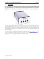
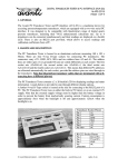
The QUARTZDYNE® Q-Link interface incorporates a microprocessor to compute pressure and temperature
for up to four digital transducers. Multiple Q-Links can be connected to the same RS-232 bus. Flash memory
is integrated for data logging and device settings. A real time clock is included for time stamping data. The
Q-Link provides four digital transducer ports, one RS-232 communications port, and one power input port.
The serial computer interface allows the user to select the units of pressure and temperature, and permits
zero and span adjustments. The user can select which data is transmitted to the computer. Q-Link
automatically downloads any connected digital transducer’s coefficient file. User-selected options (such as
units of pressure and temperature) can be written to memory, so that the Q-Link operates in the desired
mode on "power-up."
A user-friendly Q-Link update software package can be downloaded from www.quartzdyne.com. The
software will automatically load the new firmware via RS-232 into the Q-Link ’s flash memory. Quartzdyne
also provides a Q-Link interface software package that simplifies the setup.
QLinkManual200809.doc
Quartzdyne Q-Link Operating Manual September 2008
Page 4
2.
ELECTRICAL SPECIFICATIONS
2.1
Absolute Maximum Ratings
Supply Voltage ........................................0 to 6.8V*
Supply Current ........................................300mA
2.2
Environmental
Operating Temperature...........................0 to 60°C
Storage Temperature..............................-40 to +80°C
Hermeticity ..............................................Dust Proof
2.3
Power Supply
Power Supply Connector ........................3.5 x 1.3 mm center positive P-7
Supply Voltage ........................................3.6 to 6.3 VDC*
Supply Current ........................................135 mA typical (Q-Link only)
................................................................+10 mA per Digital Transducer
Recommended Power Supply ................3.0 VDC @ 400mA Unregulated*
2.4
Serial Communication
RS232 (IBM AT compatible) ...................8 data bits, 1 stop bit, no parity, Up to 115.2Kbaud
Cable .......................................................9 pin DB9 M-F straight through, fully shielded.
Max 15m
2.5
I²C Communication
Input Voltage ...........................................3V Logic Levels
Internal Pull-Up Resistor .........................10 kΩ
Cable .......................................................Fully shielded. Max 2m
2.6
Data Logging
Flash RAM ..............................................896KB Storage Space
Data Points..............................................229,376 Data Items
................................................................76,458 data sets (time, pressure, temperature)
Data Retention ........................................>10 Years
*Warning – Unregulated supplies may have dangerously high DC voltages. Do not use a supply that
exceeds maximum voltage at minimum supply current. See section 3.3.
QLinkManual200809.doc
Page 5
Quartzdyne Q-Link Operating Manual September 2008
HARDWARE
3.
3.1
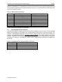
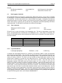
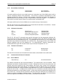
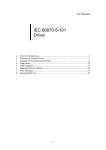
Transducer Connections
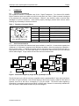
The transducer interface is compatible with Q-Link Digital Transducers. Four female 6-Pin MiniDin
Digital Transducer ports are located on the Q-Link back panel (see Table 1). Each connector is designed
to be protected from reasonable static discharges. However, care should be taken to prevent static
discharges to Q-Link’s connectors. Users should properly discharge potential static sources before
handling any of Quartzdyne’s electronic devices.
Table 1. Transducer Connector Pinout
GND
SDA
SCL
Pin #
Label
Description
1
A2
Device Address
2
Vcc
3VDC Output
3
A1
Device Address
4
SCL
I²C Clock 100KHz Max
5
SDA
I²C Data 100KHz Max
6
GND
Ground
A1
Vcc
A2
6-Pin Mini DIN Connector
3.2
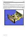
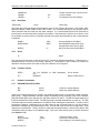
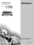
Serial Communications
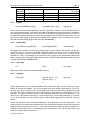
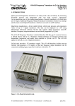
Q-LINK can communicate with standard serial ports available on most PCs. Communication speeds from
1200baud to 115.2kbaud are supported, with 9600 baud as default. Other line settings are 8 data bits, 1
stop bit, and no parity. A multi-device network may be connected using a common serial port and a YType cable for all devices. The total cable length in a multi-device network is the sum of the individual
branch cables lengths. Longer cables will lower the network’s max baud rate.
RS-232
RS-232
Y-Cable
I2C
Q-Link
Q-Link
(a)
I2C
Digital Transducer
(b)
Digital Transducer
Figure 1. Connection Diagram (a) single Q-Link, (b) Multiple Q-Links.
The RS-232 port on the Q-Link is directly compatible with the standard IBM AT style (9-pin) serial port,
see Table 4 for pin functionality. Note that the labeling of the RX and TX pins is relative to the device in
question; thus RX on the host is connected to TX on the Q-LINK. The RS-232 cable supplied by
Quartzdyne is a standard straight through DB-9P to DB-9P cable. Beware of commercially available RS232 “null modem” cables where several of the pins are swapped.
QLinkManual200809.doc
Page 6
Quartzdyne Q-Link Operating Manual September 2008
Hardware handshaking is not required by the protocol. Since most AT type computers require DTR and
CTS to be active, these lines are supported through a loop back. Communications are half-duplex (only
one device may talk at a time).
Table 2. RS232 Cable Connections
Pin Number RS232 DTE (IBM AT)
1
*Receive Line Signal Detect
2
Receive Data (RXD)
3
Transmit Data (TXD)
4
Data Terminal Ready (DTR)
5
Signal Ground
6
Data Set Ready (DSR)
7
Request to Send (RTS)
8
Clear to Send (CTS)
9
*Ring Indicator (RI)
* These lines are not required for communication.
Transducer Interface (DCE)
DSR/DTR
Transmit Data
Receive Data
DSR/DTR
Signal Ground
DSR/DTR
CTS/RTS
CTS/RTS
*N/A
3.3
Linear Wall Mount Power Supplies
Linear power supplies are simple devices rated to provide a voltage at a given current. Any linear power
supply’s output voltage will be greater than its rating when the load current is less than its rating. For
example a 3.0DC@400mA supply will have a much higher output voltage if the load current is 50mA. This
property could potentially create an over/under voltage problem if the power supply is not chosen
carefully. Quartzdyne recommends a 3.0 Vdc @ 400mA supply, but we do recognize that this may not be
possible for all customers. The following is a table of power supply ratings that should be compatible with
the Q-LINK.
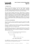
Table 3. Unregulated Power Supply Voltage vs. Current
Voltage(V)
6.0
5.0
4.5
3.0
QLinkManual200809.doc
Current(mA)
100
100-150
150-250
250-400
Quartzdyne Q-Link Operating Manual September 2008
Page 7
3.4
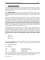
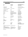
Battery Replacement
Warning! The Q-Link Digital Transducer Interface contains static sensitive devices. Use static
prevention measures when accessing the inside of the case. Work only in an ESD safe work area.
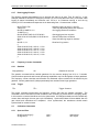
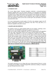
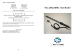
To open the case, remove the four screws from the front end of the enclosure. Carefully slide the front
panel and plastic trim from the enclosure exposing the electronics as shown in Figure 2. Insert a flat
head screwdriver in the slot on the battery holder, and gently pry the battery up until it can be slid out if its
socket. Insert the new battery with the “+” sign on the top. Use only Panasonic type BR2330 or
equivalent batteries. Slide front panel and electronics into enclosure using the bottom PCB groove and
insert and tighten the four screws.
Figure 2. Battery Replacement
QLinkManual200809.doc
Quartzdyne Q-Link Operating Manual September 2008
4.
Page 8
COMMUNICATIONS PROTOCOL
Any commercially available terminal emulator can be used to communicate with the Q-Link. The program
“LTalk.exe” available from Quartzdyne is specifically tailored for this use. The Windows program
“QConsole.exe”, also available from Quartzdyne implements all of the commands listed below with a
simple windows interface.
4.1
Command Structure
In the command documentation square brackets ([]) indicate optional parameters; a vertical bar (|)
indicates alternate parameters. Uppercase letters indicate literal expressions, lowercase letters indicate
data formats and italics represent data values and descriptions. The "¬" character indicates a CR-LF
sequence.
Commands are prefixed by the hash character (#) followed by two numeric digits, which indicate the
address. Up to four devices may be connected to each Q-Link. Because each device must have its own
unique address, the Q-Link will occupy a range of four consecutive addresses on the bus. For example,
if the Q-Link is set at address #01 (the default), its four devices can be accessed using addresses #01
through #04. The connector on the left, labeled 'A', will be associated with the lowest address, and so
forth. Address #00 is an all-call, or global command; all Q-Link modules on the bus will execute the
command, but none will reply. If multiple Q-Link modules are to be used on the same serial port, their
addresses must include unique ranges. For example, a second Q-Link could be set to use addresses
#05-#08. The Q-Link base address may be changed by issuing the AD (set address) command. Please
refer to Section 4.6.1 for more details about the AD command.
Commands and responses are terminated by a CR-LF (¬) sequence. The null command (#nn¬) can be
used to repeat the previous command. The equal sign (=) is used to program a value. Data items within
a command or response are separated by commas (,). Multiple commands may be sent in a single
command line with each command separated by a semicolon (;). The responses will be comma
separated (see example). Braces ({}) are used to enclose commands that include CR-LF sequences
such as the contents of log data or a calibration file. Invalid commands or data respond with "ERROR
nn¬", where nn indicates the particular error (See Section 6). A typical command/response sequence is
shown.
#01D1;D2¬
4522.45,120.24¬
#01¬
4522.47,120.22¬
A copy of all programmable data is stored in nonvolatile memory. On power-up, defaults are assigned
based on the contents of this memory. The contents of this memory are accessed using EEPROM
commands (See Section 4.7.1).
4.2
Data Access Commands
4.2.1
Read Data
D[1]¬
D2¬
D3¬
D4¬
±nnnnn.nnn
±nnnnn.nnn
Nnnnnnnnn
Nnnnnnnnn
Primary Output (Pressure)
Secondary Output (Temperature)
Frequency Ratio 1
Frequency Ratio 2
Data commands are used to read the intelligent transducer data. Only fresh data will be sent (i.e. data
which hasn't already been read), so there may be a delay of up to one gatetime before the response is
sent. If data is not available for any other reason, an appropriate error indicator will be sent.
QLinkManual200809.doc
Page 9
Quartzdyne Q-Link Operating Manual September 2008
D1 and D2 are the calculated Primary (Pressure) and Secondary (Temperature) outputs reported in
either the default or alternate calibrated units as described in Section 4.2.2. D3 and D4 are 32-bit
integers equal to 2^32 times the sensor frequencies divided by the reference frequency. These numbers
are used as the inputs to the polynomials defined by the coefficient files.
It may be useful to combine multiple data statements in the same command line so that one request for
data will return all of the data needed. The data commands can be used in the global mode to set up a
command format as illustrated below.
Command
#00D3;D4¬
#01¬
#02¬
4.2.2
Response
Comments
global command for F1 and F2
#01's response
#02's response
13054114,32541297¬
12463731,31031324¬
Select Units
UN[1][=n|name]¬
UN2[=n|name]¬
name¬
name¬
Primary Units (Pressure)
Secondary Units (Temperature)
UN selects the units to be used from the programmed units table. The units may be selected by name or
number. The name of the currently programmed units is returned. The name search is not case
sensitive. If the number is out of range [1-8] or the name cannot be found, an error is returned.
#01UN1=psi¬
#01UN1=Bar¬
#01UN2=C¬
#01UN2=F¬
4.2.3
psi¬
Bar¬
C¬
F¬
Pressure Units to psi
Pressure Units to bar
Temperature Units to °C
Temperature Units to °F
Program Units
UP[1][=name[,scale[,offset]]]¬
UPn[=name[,scale[,offset]]]¬
name,scale,offset¬
name,scale,offset¬
Units Program 1
Units Programs 2-8
The UPn command is used to program each of the eight available units programs. If n is not specified, 1
is assumed. The units program includes a name by which the units are referred (maximum 5 characters),
a scale factor, and an offset. The scale factor defaults to 1.0 and the offset to 0.0. The output is
computed based on the following equation where the units of each term are shown in parentheses.
Dout ( units) = scale ( units / CU ) × Dcalc ( CU ) + offset ( units) .
CU is the calibrated unit as specified in the coefficient file (See Section 4.5.4). For QUARTZDYNE®
Pressure Transducers, the calibrated units are psi for D1 (primary output) and °C for D2 (secondary
output). It is the user's responsibility to verify that the scale factors are appropriate for the calibration
type. Note: Programming a unit does not select it! The Q-Link is initially programmed with the units
conversion factors shown below. Any of these may be changed by the user. Each program can be used
with either D1 or D2. Use the EW command (Section 4.7.1) to store the changes permanently.
Program
UP1
UP2
UP3
UP4
UP5
UP6
UP7
UP8
QLinkManual200809.doc
Name
psi
bar
MPa
mH2O
C
K
F
R
Scale
1.0
0.0689476
0.00689476
0.70307
1.0
1.0
1.8
1.8
Offset
0.0
0.0
0.0
10.335
0.0
273.15
32
523.67
Page 10
Quartzdyne Q-Link Operating Manual September 2008
Example:
#01UP8=Atm,0.0680272¬
#01UN1=8¬
4.3
Atm,0.0680272,0¬
Atm¬
Units Program 8 to Atmospheres
Select Atm as Pressure units
Data Logging Commands
The QUARTZDYNE® Q-Link Interface is supplied with 1MB of flash memory, most of which is available
for data logging. It also has a battery-backed timekeeping chip so that time information may be included
in the data log. Q-Link's power must be on in order for data to be logged. Configuration and data are
retained when power is removed. If power is removed during an active logging session, data logging will
resume when power is restored. The Log data and Log configuration are stored separately from device
configuration data. The EW and ER commands do not affect the data logger.
4.3.1
Time Commands
TM[=[yy]yy:mm:dd:hh:mm:[ss]]¬
TS[=ts]¬
yyyy:mm:dd:hh:mm:ss¬
ts¬
Time
Time in seconds
TM and TS set or report the setting of the timekeeping chip. TM uses an international 24 hour time
format. TS reports/sets time in seconds since 12:00 Midnight on Jan. 1, 1970 (1970:01:01:00:00:00). The
TM and TS commands are also used to determine the format of the LD command. The range of the TM
format is as follows:
[yy]yy
Mm
Dd
Hh
Mm
Ss
4.3.2
[19]70-[20]69
1-12
1-31
0-23
0-59
0-59
Year
Month
Day of Month
Hours
Minutes
Seconds
Log Initialize/Delete
LI[=dd[,dd][,dd][,dd][,dd]]¬
TM|TS[,D1] ... [,D4]¬
Initialize Log
LI initializes the data logging functions for a channel (or all channels if #00LI is used), and programs
which data items will be stored. This command may take several seconds to complete, because it may
have to erase the flash memory, which is a time consuming process. The response will come after any
erasing of memory is finished. The data in the log is stored as 4 byte floating point numbers. Time is
always stored, in addition to at least one of the data items D1-D4. The table below shows how many
points can be stored depending on how many data items are stored. Note that there are four
independent channels (A-D) which share this memory space, so if you log data on more than one
channel, the number of points per channel is reduced accordingly. Within the data logging memory are
fourteen sectors. Each of these sectors is allocated to one of the four channels on a ‘first come, first
served’ basis. A sector cannot be shared by more than one channel. This means that one channel might
report that its log is full (Error 14), while other channels still have room for more data points. Use the
#00LI= command to erase logged data for all channels, ensuring that the maximum amount of space is
available for subsequent data logging. After the log is initialized, the log rate and start/stop time must be
set for logging to commence. Power must be on for data to be logged. The log settings and logged data
are preserved during power down. (See example in Section 4.3.7.)
QLinkManual200809.doc
Page 11
Quartzdyne Q-Link Operating Manual September 2008
Number of Example Command
Data Items
1 #01TM,D1
2 #01TM,D1,D2
3 #01TM,D1,D3,D4
4 #01TM,D1,D2,D3,D4
4.3.3
Points per Sector
8192
5461
4096
3276
Points per Full Log
(14 Sectors)
114688
76454
57344
45864
Log Rate
LR[=nsec[AND|OR Dn=step]]¬
nsec[AND|OR Dn = step]¬
Logging rate
Data is stored at time intervals specified in seconds. Optionally a condition may be included based on
one of the logged data items. In the AND mode, data will be logged at the time interval only if the data Dn
has changed by at least the value of step. In the OR mode data will be logged at the time interval OR if
the data has changed by at least step since it was last logged. If the number of seconds is set to zero, all
data points will be logged as they become available (at the gatetime rate). The logging rate may be
changed while data is being logged. (See example in Section 4.3.7.)
4.3.4
Log Start/Stop
LS[=START|start[,stop]|STOP]¬
start[,stop]|STOPPED¬
Start/Stop times
Data logging will commence when the time programmed by start is reached and continue until the time
specified in stop. If no stop time is specified, logging will continue until the log is full. To start/stop data
logging immediately, use the words START or STOP instead of the actual times. The times will be
reported as in TM or TS depending on the last format used. Logging may be stopped and started at will
without destroying previously logged data. Only the most recently programmed start and stop times are
reported. (See example in Section 4.3.7.)
4.3.5
Log Length
LL¬
nnnnn¬
Log Length
Reports the number of data sets currently stored in the log.
4.3.6
Log Dump
LD[n1[,n2]]¬
time,nnnn.nn[,nn ... ]¬| {¬
time,nnnn.nn[,nn ... ]
.
}¬
Dump Log
Dumps data from the log in the format specified above. When more than one line of data is returned,
braces will enclose the response. Time will be reported in the most recently used format (LI, TM or TS).
All other items will be dumped in the currently programmed units and with currently programmed scale
and offset. Units may be changed during the data logging. A single data set is transmitted if only n1 is
specified. The range of data sets from n1 to n2 is transmitted if both n1 and n2 are specified. n1 can
range from 1 to the number returned by LL. n2 can range from n1 to the number returned by LL. If neither
n1 nor n2 are specified, the entire data log will be dumped. Data logging will be suspended during log
dumps.
Please note that serial communications handshaking is not supported by the Log Dump function. This
means that there is a chance that characters will be lost if the receiving program cannot keep up with the
character stream being sent by the Q-Link. If you find that some lines of data are missing characters, try
dumping at a slower baud rate, or try dumping the log in smaller pieces. Also, the only way to abort a log
dump is to cycle the power on the Q-Link.
QLinkManual200809.doc
Page 12
Quartzdyne Q-Link Operating Manual September 2008
4.3.7
Data Logging Example
The following example demonstrates how to program the data log to store Time, D1 and D2. In this
example, data will be stored if D1 changes by at least 1.0, but no more than once every 10 seconds. Data
logging is started immediately and continues until 7:00 a.m. on Christmas morning or until the log
memory is full. Commands and responses are on alternating lines. Comments are in italics.
#01LI=TM,D1,D2¬
TM,D1,D2¬
#01LR=10 AND D1=1.0
10 AND D1=1¬
#01LS=START,2003:12:25:07:00:00¬
2003:12:24:16:59:59,2003:12:25:05:00:00¬
#01LL¬
15¬
#01LD 11,15¬
{¬
2003:12:24:23:59:45, 1012.21, 1.512¬
2003:12:24:23:59:55, 1018.32, 1.513¬
2003:12:25:00:00:10, 1017.31, 1.514¬
2003:12:25:00:05:23, 1016.31, 1.515¬
2003:12:25:00:05:33, 1013.15, 1.516¬
}¬
4.4
Frequency Counter Commands
4.4.1
Gatetime
GA[=gatetime]¬
nn¬
Initialize Logging for time, D1 and D2
There may be a delay before this response
Set Logging Rate and Conditions
Start logging and set stop time.
Start and Stop times confirmed.
Some time later log length is checked.
Read last 5 log entries.
Gatetime in seconds
The gatetime command allows variable gatetimes for the counters ranging from 0.01 to 2 seconds.
Communications protocols and internal processing capabilities may limit throughput at faster gatetimes.
The frequency counter resolution and therefore the calculated output resolution will be affected by the
gatetime. Shorter gatetimes will yield proportionately less resolution than longer gatetimes.
4.4.2
Trigger
TR¬
TR¬
Trigger Counters
The trigger command synchronizes the frequency counter gate with the software command. The
command is most useful when several transducers are monitoring a process which is changing rapidly.
In this case the command should be sent in the global mode. All intelligent transducers will invalidate any
current data, and begin the next gate cycle immediately. Synchronized data will be available after the
gate closes and calculations are completed. Once synchronized, the transducers should remain
synchronized for several minutes.
4.5
Calibration Commands
4.5.1
Span and Zero
S[1|2][=span[,range]]¬
Z[1|2][=zero]¬
QLinkManual200809.doc
span¬
zero¬
Span Adjust
Zero Adjust
Page 13
Quartzdyne Q-Link Operating Manual September 2008
The S and Z commands set the span and zero for two point calibrations. S[1] and Z[1] refer to the
primary output (pressure). S2 and Z2 refer to the secondary output (temperature). Zero and span are
input in the current units. They are adjusted automatically when units are changed. The span adjustment
is the desired change at full scale. If a value other than full scale is used to calculate the span
adjustment, include that value in the range argument. The following equation is used to calculate the
interface output.
span ⎞
⎛
⎟ × ( Dcalc + zero) .
Dout = ⎜1 +
⎝
D max ⎠
In a typical two point calibration, the span and zero are initially set to zero. Data is taken at the zero point
and zero is calculated as:
zero = Dactual - Dmeasured .
Enter the zero using the Z command.
#01Z1=zero¬
zero¬
Next, data is taken at a known point near full scale. Span is calculated as:
span = Dactual - Dmeasured .
Enter the span adjustment using the S command.
#01S1=span, Dmeasured ¬
span¬
The returned span will have been adjusted for the calibrated full scale load. Use the EW command
(Section 4.7.1) to store the changes permanently.
#01EW¬
0¬
Note: Two point calibration trimming is not generally recommended for QUARTZDYNE® Transducers.
4.5.2
Full Calibration
CA[L][={file contents}]¬
{¬file contents}¬
Full Calibration
CA accepts and echoes a hex coefficient file in the format provided by Quartzdyne. The format of this file
is described in the digital transducer user's manual and documentation disk. The file contents are sent
with surrounding braces ({}). Both primary and secondary coefficients are included in the hex coefficient
file. If the file's format is incorrect, or if its checksums are not received correctly, an error will be returned
and the coefficients will be marked as invalid. Coefficients may be restored to a valid state by sending a
correct coefficient file via the CA command.
Note that the CAL command reads (or stores) coefficients from (or in) Q-Link RAM, which is only
temporary. To copy the coefficients to the non-volatile memory in the transducer itself, making them
more permanent, use the CW command described below. In the example below, the full command is
sent before any response is received. Previous coefficients may be restored by rebooting Q-Link or by
issuing the CG command.
COMMAND
#01CA={¬
FileContents
}¬
RESPONSE
{¬
FileContents
}¬
MEANING
Calibration
#01CW¬
0¬
Store Permanently
QLinkManual200809.doc
Page 14
Quartzdyne Q-Link Operating Manual September 2008
4.5.3
Get and Write Coefficients
CG¬
CW¬
channel status¬
channel status¬
Get Coefficients
Write Coefficients
CG copies coefficients from the non-volatile memory of a transducer into Q-link's RAM, where it will be
used for calculating pressure and temperature. This function is performed automatically for each
attached transducer on boot-up. During normal operation, Q-Link polls all inactive I2C channels on
approximately a one-second interval to see if a new transducer has been plugged in. If a transducer is
discovered on a formerly inactive channel, its coefficients are automatically read.
CW copies coefficients from Q-Link's RAM to the non-volatile memory of the transducer.
Both CG and CW return the channel status for the channel that the transducer is connected to. A status
of 0 is normal. A non-zero status indicates an error.
4.5.4
Calibration Information
CD¬
CU[1|2]¬
CR¬
CT[1|2]¬
dd mmm yyyy¬
Default units, alternate units¬
Pmax, Pmin, Smax, Smin¬
Pressure|Temperature|Other¬
Calibration Date
Calibrated Units
Calibration Range
Calibration Type
The CD, CU, CR, and CT commands return specific information from the programmed calibration file.
CR will return the primary range (Pmax and Pmin) in the default units for D1 and the secondary range
(Smax and Smin) in the default units for D2. The calibration type returned by CT is the name of the
parameter being measured as specified in the coefficient file. CU returns the name of the default and
alternate calibrated units from the calibration file. For QUARTZDYNE® Pressure Transducers, the
standard calibration types and units are Pressure in psi or Bar and Temperature in C or F.
4.5.5
Transducer Information
M¬
ID¬
nnnnn-nnnn¬
nnnnnnnn¬
Model Number
Serial Number
The M and ID commands return the model and serial number as downloaded in the coefficient file.
4.6
Communications Protocol Commands
4.6.1
Device Address
AD[=address] ¬
nn¬
Q-Link Base Address
The address command sets the Q-Link base address. The response will be the new address. Base
addresses are limited to numbers between 01 and 96. Because the Q-Link has four device ports, and
because each device requires its own unique address, each Q-Link uses a range of four consecutive
addresses beginning with the base address. For example, if the Q-Link address is set to 01 (the default),
the devices connected to it may be accessed using addresses 01-04, with 01 corresponding to the port
labeled 'A' and so forth. If multiple Q-Link modules are to be connected to the same serial port, they
should be programmed to unique address ranges. In other words, assuming that the base address of the
first Q-Link is 01, a second Q-Link connected to the same serial port should be set to address 05 or
greater to avoid the overlapping of address ranges. To avoid conflict, the address of a second Q-Link
must be changed from the default of 01 while it alone is connected to the serial port.
QLinkManual200809.doc
Page 15
Quartzdyne Q-Link Operating Manual September 2008
#00AD=05¬
#05AD¬
#05EW¬
4.6.2
05¬
0¬
Global: Assumes only 1 device on bus
Confirm change
Permanently store new address
Baud Rate
BR[=baud]¬
nnnn¬
Baud Rate
The baud rate command allows communications at any of the following baud rates: 1200, 2400, 4800,
9600 (the default), 19200, 38400, 57600, and 115200. The command will reply at the old baud rate to
allow verification that the baud rate has been changed. It is recommended that an EW command be
issued (at the new baud rate) after setting this command. If the baud rate of a device is not known, it will
be necessary to issue a series of command requests at the baud rates listed above until a valid response
is obtained.
4.6.3
#01BR¬
#01BR=9600¬
1200¬
9600¬
#01EW¬
0¬
Communicating at 1200 Baud
Set 9600 Baud (reply still at 1200)
Change Baud rate of host to 9600
Store new baud rate at 9600 Baud
Reset
X¬
Reset
This command cycles power to the I2C ports A-D, resetting all attached transducers. Following this, a
watchdog timeout is forced on Q-Link itself, rebooting it. The purpose of this command is to allow the
operator to remotely cause a full reset in case of a transducer or Q-Link glitch.
4.6.4
Firmware Version
VE[R]¬
VF¬
Ver 2.01 03/02/03 (c) 1996 Quartzdyne,
Inc.¬
0D020201
4.7
Hardware Commands
4.7.1
EEPROM (Flash) Read, Write
ER¬
EW
status¬
status¬
Q-Link Version
Device FPGA Version
Read Non-Volatile Memory
Write Non-Volatile Memory
Certain key Q-Link parameters are stored in non-volatile (Flash) memory, so that they persist even after
power down. These parameters (and their related commands) include: Gatetime (GA), Device Address
(AD), Baud Rate (BR), Units (UN and UP), and Span and Zero (S and Z). The ER command copies all of
these parameters from Flash to RAM. The ER command is invoked automatically on power up. The EW
command copies all of these parameters from RAM to Flash, making them permanent. In order to avoid
permanently changing a parameter that you didn't intend to, we recommend that you use the following
procedure to change only one parameter at a time: First call ER to get Q-Link into a known state. Then
change the one parameter. Finally, call EW to make that change permanent. Both the ER and the EW
commands return the status of the hardware flags. This is the same status given by the ES command
(see Section 4.7.2).
#01EW¬
#01CA={cffile}¬
#01EW¬
QLinkManual200809.doc
19, 0
{cffile}¬
0¬
Clear Error State (?)mg
Download Coefficient File
Save settings in non volatile memory
Page 16
Quartzdyne Q-Link Operating Manual September 2008
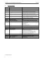
4.7.2
Hardware Status Command
ES¬
status¬
Hardware Status
The status of certain hardware conditions can be read. If this value is non-zero, an error state exists.
The hardware status flags are bit mapped into a 16 bit integer. The bit fields are shown in Table 4. If
errors persist after the suggested corrective action has been taken, please note the conditions and status
codes and report them to Quartzdyne.
Table 4. Hardware Status Bit Definitions
Bit
0
1
2
3
4
5
6
7
8
Value
1
2
4
8
16
32
64
128
256
Meaning
No Pressure Frequency
No Temperature Frequency
No Transducer Detected
Bad or No Coefficient File
Checksum Error
Dead Battery
Bad Command
Real Time Clock Error
Timer Overflow
9
512
Event Overflow
10
11
12
13
1024
2048
4096
8192
Zero Divide
Stray Interrupt
Flash Memory Error
I2C Error
4.7.3
Corrective Action
Check Transducer and Cable
Check Transducer and Cable
Check Transducer and Cable
Download Coefficients/Check Transducer
Download Coefficients
Replace Battery
Check Host Software
Check Battery/Hardware Problem
Reduce Baud Rate or RS232 Traffic. Increase
Gate Time.
Reduce Baud Rate of RS232 Traffic. Increase
Gate Time.
Software Error
Hardware Problem
Hardware Problem
Check Transducer and Cable
Error Message
EM[nn]¬
message¬
Error Message
If a command is not recognized, data is out of range, or the transducer is not operating properly, the text
"ERROR n" will be sent instead of the normal response to a command. To receive a full message rather
than a number, issue the EM[n] command where n is the number of the message you want to receive. If
[n] is omitted, the message corresponding to the most recent error will be sent. The error messages and
likely causes and remedies are listed in Section 6.
Some error states are persistent, causing them to be reported at the beginning of each reply. These error
messages may be suppressed by issuing an EM[n] command where n is either explicitly set to the
persistent error message number or defaults to it because it was the last error reported. Once an error
has been suppressed in this fashion, it will not be reported until the condition corrects itself and then fails
again or the power is cycled off then on.
The ES command will continue to report the suppressed error condition as long as it persists.
4.8
In-application Programming Feature
Q-Link has an in-application programming feature, meaning that its firmware can be upgraded via the RS232 serial port. As new versions of the software are developed, these will be posted on Quartzdyne's
website (www.quartzdyne.com) for downloading. The QConsole application supplied by Quartzdyne is
used to upload the software updates into the Q-Link.
QLinkManual200809.doc
Page 17
Quartzdyne Q-Link Operating Manual September 2008
5.
COMMAND SUMMARY
D[1]¬
D2¬
D3¬
D4¬
±nnnnn.nnn
±nnnnn.nnn
nnnnnnnnn
nnnnnnnnn
Primary Data (Pressure)
Secondary Data (Temperature)
Frequency Ratio 1
Frequency Ratio 2
UN[1][=n|name]¬
UN2[=n|name]¬
name¬
name¬
Primary Units (Pressure)
Secondary Units (Temperature)
UP[n][=name[,scale[,offset]]]¬
name,scale,offset¬
Unit Program (1-8)
S[1|2][=span[,range]] ¬
Z[1|2][=zero] ¬
span¬
zero¬
Span Adjust
Zero Adjust
CA[L][={file contents}]¬
CD¬
CU[1|2]¬
CR¬
CT[1|2]¬
M¬
ID¬
{¬cffile contents}¬
dd mmm yyyy¬
default units, alternate units¬
Pmax, Pmin,S max, Smin¬
Pressure|Temperature|Other¬
nnnnn-nnnn¬
nnnnnnnn¬
Full Calibration
Calibration Date
Calibrated Units
Calibration Range
Calibration Type
Model Number
Serial Number
CG¬
CW¬
channel status¬
channel status¬
Get Coefficients
Write Coefficients
GA[=gatetime]¬
TR¬
0.01 up to 2¬
TR¬
Gatetime in Seconds
Trigger Counters
VF¬
VE[R]¬
AD[=address] ¬
BR[=baud]¬
X¬
nnnnnnnn¬
revision message¬
nn¬
nnnn¬
FPGA Revision
Software Revision
Response Address
Baud Rate
Reset
EM[nn]¬
ES¬
ER¬
EW
message¬
status¬
status¬
status¬
Error Message
Hardware Status
Read Configuration from Flash
Write Configuration to Flash
TM[=[yy]yy:mm:dd:hh:mm:[ss]]
¬
TS[=ts]¬
LI[=dd[,dd][,dd][,dd][,dd]]¬
LR[=nsec[AND|OR Dn=step]]¬
LS[=START|start[,stop]|STOP]¬
LL¬
LD[n1[,n2]]¬
yyyy:mm:dd:hh:mm:ss¬
Time
TM|TS[,D1] ... [,D4]¬
nsec[AND|OR Dn = step]¬
start[,stop]|STOPPED¬
nnnnn¬
Time in seconds
Initialize Log
Logging rate
Start/Stop times
Log Length
Dump Log
QLinkManual200809.doc
Page 18
Quartzdyne Q-Link Operating Manual September 2008
6.
ERROR MESSAGES
Error
Error 0
Error 1
Error 2
Error 3
Description
No Error
Bad Coefficients
Error 4
Invalid Data
Error 5
Named Units Not Found
Error 6
Numeric Overflow
Error 7
Error 8
Error 9
Error 10
Error 11
Command Too Long
Response Too Long
Serial Port Overrun Error
Serial Port Parity Error
Serial Port Framing Error
Error 12
Error 13
Error 14
Error 15
Error 16
Log Hardware Not Installed
Log Initialization Error
Data Log is Full
Data Log is Empty
Protocol Overrun
Error 17
Error 18
Error 19
Error 20
Error >20
Hardware Error - Check Status (ES)
Sensor Frequency or Timebase Error
Memory Checksum Error
Battery Low Error
Hardware Error (Number = ES)
Unrecognized Command
QLinkManual200809.doc
Possible Causes/Relevant Commands
Download using CAL1={file contents}
N/A
Semicolon instead of comma
Missing characters in host serial software
Numeric data out of range
String data contains too many characters
UN[1|2]=name - name not found in units table
Use UPn to program units into the units table
Inappropriate Coefficients (CA)
Transducer readings out of range
Try shorter commands
N/A
Try shorter commands, slower baud rate (BR)
N/A
Incorrect Baud Rate (BR)
Polarity Reversal
ESD Event
Break Character Sent
Timekeeper Chip not responding (TM,TS, LI)
No log settings, try setting log.
N/A
N/A
Characters sent by host or other device before
addressed device respondedHost time-out shorter than gatetime (GA)
Multiple devices set to same address (AD)
Too much time between CR and LF
See Table 4
See Table 4
EEPROM Data corrupt, See Table 4
Replace Battery
See Table 4