1
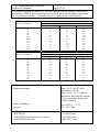
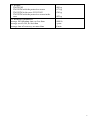
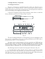
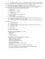
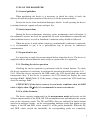
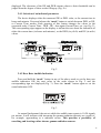
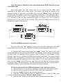
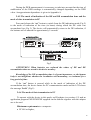
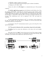
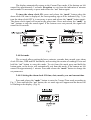
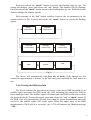
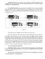
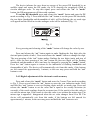
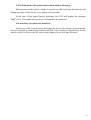
PROGRAMMABLE DOSIMETER
PM1203M
OPERATING MANUAL
POLIMASTER Ltd.
Minsk 2001
1
CONTENTS
1 DESCRIPTION AND OPERATION OF THE DOSIMETER ....
1.1 Application of the dosimeter………………………………….….
1.2 Delivery kit ………………………………………………………
1.3 Specifications …………………………………………………….
1.4 Design and theory of operation ……………………………..……
2 USE OF THE DOSIMETER …….……………………………….
2.1 General guidelines …………………………………………..……
2.2 Safety instructions ………………………………………………..
2.3 Preparation for use ………………………………………..………
2.4 Use of the dosimeter ……………………………………..……….
3 MAINTENANCE …………………………………………………..
4 TROUBLESHOOTING ……………………………………………
5 VERIFICATION TECHNIQUE………………………..…….……
6 STORAGE AND SHIPPING …………………………….………...
7 WARRANTY ……………………………………………….……….
Page
4
4
5
6
9
11
11
11
11
11
21
22
23
27
28
ATTACHMENT A Dependence of time of reading stabilization on
the DER value…………..….……………………
29
2
This Operating Manual combined with the passport is intended to describe the
design, operation and use of the programmable dosimeter PM1203M. The Operating
Manual includes the general description, specifications of the dosimeter, instructions for
its maintenance, as well as some other information necessary for the proper operation of
the dosimeter and a full realization of its possibilities.
During manufacturing of the programmable dosimeter PM1203M some changes
may be introduced in its electrical scheme, construction and software that do not
influence the specifications and metrological parameters and, therefore, may be not
specified in this manual.
3
1 DESCRIPTION AND OPERATION OF THE DOSIMETER
1.1 Application of the dosimeter
The PM1203M programmable dosimeter (hereinafter referred to as the device) is
designed to provide:
- continuous measurement of the ambient dose equivalent rate of gamma
•
radiation Η * (10) (hereinafter DER);
- measurement of the ambient dose equivalent of gamma radiation H*(10)
(hereinafter DE);
- measurement of the time of the ambient dose equivalent accumulation;
- storage in the memory and transmission to a personal computer of the DER
measurement history;
- indication of the time in hours, minutes and seconds, the date and month and
year on the digital liquid crystal display.
The PM1203M programmable dosimeter may be used by a variety of specialists
(personnel of nuclear facilities, radiological and isotope laboratories, officers of the
emergency services, civil defence, fire brigades, police, customs and border services), as
well as by a wide range of users to measure the DER and DE of gamma radiation.
4
1.2 Delivery kit
Table 1.
Item
Programmable
dosimeter
PM1203M
Battery 1)
Operating manual
IR adapter IR
Computer Link ACTIR220L
Case for shipping
Type
Quantity
14804920.006-2001
1
V357
412118.006-01
2
1
426434.008
1
412915.002-07
1
Note
The present
operating manual
contains verification
technique
Available as an
option
Note:
1) similar types of batteries are acceptable
5
1.3 SPECIFICATIONS
1.DER measurement range
2.DER threshold range
0.1 – 2000 µSv/h
0.1 – 1999.99 µSv/h,
step is 0.01µSv/h
3. Maximum permissible intrinsic relative ± (15 + A1/! + A2·!) %,
where ! − DER value, µSv/h;
error of DER measurement
A1 – coefficient 1.5 (µSv/h);
A2 – coefficient 0.0025 (µSv/h)-1
4. DE measurement range
0.01 - 9999 mSv
5. DE threshold range
0.01 – 9999.999 mSv,
step is 0.001 mSv
6. Maximum permissible intrinsic relative ± 20 %
error of DE measurement
7.Coefficient of variation
10 %
8. Range of the dose accumulation time
1 – 9999 h, step is 1 h
9.Maximum permissible additional relative
error of measurement:
- due to temperature variations from
normal to high or low
± 15 %
- at limiting values of power voltage
± 10 %
- due to humidity variations from normal
to high
± 10 %
10.Energy range
0.06 - 1.5 MeV
11.Energy response relative to 0.662 MeV
(137Cs) in the energy range:
0.06 - 0.662 MeV
± 25 %
0.662 - 1.5 MeV
± 15 %
12. DER measurement time, no more than 36 s
13.Response time when DER value is
increased more than 10 times, no more
10 s
than
14. Instability of readings during 24 hour
continuous work, no more than
±5%
15. Search mode is available
16. DER measurement start is available
17. Electronic watch accuracy at normal
conditions may be set using digital
correction at
±1 s/24 hours
18. Power supply
19. Battery discharge warning:
3 V (two V357 type batteries)
indication of partial and of critical
battery discharge
20. Battery lifetime at natural background
and audible signals activated for more than
1 year
2 min/24 hours, at least
6
21. PC communication by infrared
up to 0.2 m
interface at a distance
22. Angular response of the device for each energy does not exceed values (in %)
presented in Table 2, when the device is rotated in the horizontal plane and values
(in %) presented in Table 3 when the device is rotated in the vertical plane
Table 2
Angle of detection relative to the
direction of graduation, °
0
30
60
90
120
150
180
-30
-60
-90
-120
-150
0,059
0
±5
±5
±5
±15
±15
±15
-30
-75
-65
-35
-30
Angular response, %
Energy of gamma radiation, MeV
0,662
0
±15
±5
±5
±5
±15
±15
±15
±10
±10
±10
±15
1,25
0
±10
±10
±10
±10
±10
±10
±15
±10
±10
±10
±10
0,059
0
-20
-50
-35
-65
-30
±15
-20
±65
-95
-70
-15
Angular response, %
Energy of gamma radiation, MeV
0,662
0
±15
±15
-50
±15
±15
±15
±15
±15
-55
±15
±15
1,25
0
±15
±15
-35
±15
±15
±15
±15
±15
±15
±15
±15
Table 3
Angle of detection relative to the
direction of graduation, °
0
30
60
90
120
150
180
-30
-60
-90
-120
-150
23. Operating conditions:
- temperature range
from –15 to +60 °C with
indication on LCD,
from –40 to –15 °C without
indication, but with the storage
of the measuring data in nonvolatile memory
- relative humidity
- pressure
up to 80% at + 35 °C
84 − 106.7 kPa
24. Dimensions:
- PM1203M
- PM1203M with the protective screen
- PM1203M in the case
125x42x24 mm
125x47x25 mm
180x135x71 mm
7
25. Weight:
- PM1203M
- PM1203M with the protective screen
- PM1203M in the case 412915.002
- PM1203M with the protective screen in the
case
26. Reliability parameters:
average full operating time, no less than
average service life, no less than
average time of recovery, no more than
0.09 kg
0.17 kg
0.34 kg
0.42 kg
10000 h
6 years
60 min
8
1.4 Design and theory of operation
1.4.1 Design of the device
The device is designed as a monoblock housed in a plastic case. The device uses a
Geiger-Muller tube as a radiation detector, which converts gamma radiation quanta to
electric pulses that are processed by the microprocessor. The microprocessor controls as
well over the display, power supply and electronic watch.
A direction of graduation and the detector geometric center relative to which the
factory calibration is performed are shown in Figs. 1a and 1b.
direction of graduation
Fig.1 a
17
6
7
8
9
13
10
15
14
MODE
2
1
Sv/h
mSv
sound
set
IR
9
DOSIMETER
49
3
4
5
SET
11
12
16
geometric center of the detector
Fig. 1b
The time of reading stabilization is set automatically in inverse dependence on the
dose rate level. A dependence of the time of reading stabilization on the DER value is
presented in the Table A.1 of the Attachment A.
The device allows setting thresholds of the dose equivalent rate (DER) and dose
equivalent (DE) values. An excess of the preset thresholds may be controlled visually
(from the display readings), or audibly. The DER and DE measurements are carried out
continuously and are independent on a value indicated at the moment on the display.
The following controls are located at the front panel of the device (Fig. 1b).
1 − the “set” button is used to enter the reference mode or to exit from it (to check
the alarm clock ON time; date and month, year, minutes and seconds), to enter the set
mode and exit from it, as well as to enter the data storage mode, DER measurement
start mode, data transmission mode and to exit from these modes.
9
2 − the “mode” button is used to switch between DER, or DE, or Current Time
modes, to set the dose rate audible indication ON/OFF, to change the parameters as well
as to start measurements in the DER mode and to store the DER values.
The “set” and “mode” buttons are used in two ways: pressing (for approx. 1
second) and releasing, or pressing and holding (for approx. 3 or more seconds).
The display has the following indication elements:
3 − digital panel;
4 − dividing sign “:” (colon);
5 − dividing sign “.” (point);
6 − circular element;
7 − circular analogue scale of DE values;
8 – linear element;
9 – linear analogue scale of DER values;
10 – “dosimeter” sign indicating that the device operates in the dosimeter mode;
11 − "Current Time mode" sign (“clock" sign);
12 − "Alarm clock ON" sign indicating that the alarm clock will sound at the
preset time;
13 − "DER mode" sign;
14 − "DE mode" sign;
15 − "Sound ON" sign showing that the dose rate audible indication is set ON;
16 − "Set mode" sign;
17 – IR data port.
1.4.2 Operation modes
The main operation modes are as follows:
- DER mode;
- DE mode;
- current time mode.
The auxiliary modes of operation are as follows:
- DER measurement start mode;
- DER value storage mode;
- audible DER indication mode;
- data transmission mode;
- alarm clock and calendar reference mode;
- set mode;
- mode of digital adjustment of electronic watch accuracy;
- the mode of indication of the partial and critical battery discharge;
- the mode of indication of the device failure.
10
2 USE OF THE DOSIMETER
2.1 General guidelines
When purchasing the device it is necessary to check the safety of seals, the
delivery kit and the proper operation of the device in all the operation modes.
Protect the device from mechanical damages, shocks. Avoid exposing the device
to strong chemicals, organic solvents and open fire.
2.2 Safety instructions
During the device adjustment, checking, repair, maintenance and verification, if
the radioactive sources are used, the regulations for work with radioactive materials and
other radiation sources, as well as Standards of radiation safety should be followed.
When the device is used within a territory contaminated by radioactive materials,
it is recommended to put it in a polyethylene bag to prevent its radioactive
contamination.
2.3 Preparation for use
It is necessary to study the present manual before using the device. The device is
supplied with the inserted batteries and is ready to operate after it is unpacked.
2.3.1 Checking the device operation
Checking the device operation is performed with the control buttons. To check
the device operation it is necessary to perform the operations described in points 2.4.1 –
2.4.9. When the device operates in the DER mode, the LCD should show the natural
background value. If the device is operative, the LCD should not display the error
messages Er01 – Er04 (Table 4). If the battery voltage is normal, the LCD should not
show the message “bAt”.
ATTENTION! If the device seems to be used under conditions when the DER
value is higher than 100 µSv/h, it is recommended to insert new batteries.
2.4 Use of the dosimeter
The device operates continuously in the measurement mode and carries out the
24 hour measurements of the DER, DE, DE accumulation time and indicates the current
time on the electronic watch. The DE and DER values are indicated in digital format
and also in analogue format - on the corresponding analogue scales that appear on the
display, if the DE and DER values exceed 0.1 of the preset thresholds. When the DE
and DER values exceed the thresholds, the corresponding scales are completely
11
displayed. The closeness of the DE and DER current values to their thresholds can be
judged from the degree of these scales filling up (Fig. 1b).
2.4.1 Selection of an indicated parameter
The device displays either the measured DE or DER value, or the current time in
hours and minutes. Press and release the “mode” button to switch between DER, or DE,
or Current Time modes. Each pressing of this button changes the values in the
sequential order: Current Time - DER - DE - then again Current Time, etc. (see Fig. 2).
The corresponding signs appear on the display to inform the user about the indication of
either the current time (in hours and minutes), or the DER (in µSv/h) and DE (in mSv)
values.
MODE
MODE
Sv/h
mSv
sound
set
Sv/h
mSv
sound
set
SET
SET
MODE
Sv/h
mSv
sound
set
SET
Fig. 2
2.4.2 Dose Rate Audible Indication
Press and hold the “mode” button in any of the above mode to set the dose rate
audible indication ON; the next value in the order shown in Fig. 2 and the
corresponding sign are displayed (Fig. 3). Press the “mode” button again to set the
sound indication OFF.
MODE
Sv/h
mSv
sound
set
SET
Fig. 3
At natural background, the rate at which the audible tone repeats is 10-20 signals
per minute. It will increase with increasing the gamma radiation intensity as a result of,
for example, approaching to a radiation source. This provides a possibility of
searching and locating rather intense gamma-radiation sources.
12
2.4.3 The mode of indication of the current measured DER value and storage
of the DER value
Press and release the “set” button (Fig. 4) to switch from the DER value
indication to the DER value storage mode. The display will show the number of an
expected reading. To store the current DER value, press the “mode” button. The display
will show the next number of an expected reading increased by 1. The indication “rd - -“
means that the memory is full, i.e. 100 readings were stored. To view the stored history
it is necessary to use the data transmission mode (see point 2.4.5). The counter of
readings may be reset while in the set mode. Then each new reading will be stored in
the memory instead of the old one.
MODE
MODE
Sv/h
mSv
sound
set
Sv/h
mSv
sound
set
SET
SET
MODE
Sv/h
mSv
sound
set
SET
Fig. 4
2.4.4 The DER measurement start mode
Press two times the ”set” button to switch from the DER indication to the DER
measurement start mode (Fig.4). The LCD will show not flashing digits 00.00 µSv/h.
To start the DER measurements press the “mode” button. The digits on the LCD
will be flashing until the first measured DER value appears. As the device is measuring
the DER value, the flashing circular analogue scale is filling in. The flashing circular
analogue scale serves to indicate the DER measurement start mode. The empty circular
analogue scale corresponds to a statistical error more than 100 %; the completely filled
in scale corresponds the statistical error no more than 20 %. To store the measured DER
value, use the “mode” button. Press the “set” button to exit from the following modes:
beginning of the DER measurement, the DER measurement before the analogue scale is
completely filled in, or the mode after the measured value was stored.
The device operation in the DER measurement start mode is as follows:
1) switch the device to the state of readiness to starting the DER measurement;
2) place the device to a point where the DER value is to be measured;
3) press the “mode” button to start the measurement;
4) when the circular analogue scale is completely filled in, read the DER value
or store it in the device memory using the “mode” button;
5) press the “set” button to exit from the DER measurement start mode.
13
During the DER measurement it is necessary to take into account that the time of
stabilization of the DER readings is automatically changed depending on the DER
value. An approximate dependence is given in Appendix A.
2.4.5 The mode of indication of the DE and DE accumulation time and the
mode of data transmission to PC
Press and release the “set” button to switch from the DE indication mode (Fig.2)
to the mode of indication of the time (in hours) during which the DE value was
accumulated (see Fig 5). The device will automatically return to the DE indication, if
the buttons are left unused for approximately 5 seconds.
MODE
MODE
Sv/h
Sv/h
mSv
sound
set
mSv
sound
set
SET
SET
MODE
Sv/h
mSv
sound
set
SET
Fig.5
ATTENTION! When batteries are replaced the values of DE and DE
accumulation time are stored in the device memory.
Knowledge of the DE accumulation time is of great importance, as the human
body is not indifferent whether the irradiation was momentary, or continued for a
long period of time.
If the “set” button is pressed while in the mode of indication of the DE
accumulation time, the device enters the PC communication mode and the LCD shows
the message “IrdA” (Fig.5).
2.4.6 The mode of data transmission to PC
To operate with the device in this mode, an IR adapter (see section 1.2) and an
application program PM1203M.EXE supplied on the diskette together with the adapter
are to be used.
Minimum requirements to a computer:
• PC 486 or higher;
14
• 800X600 or higher resolution of a monitor.
• 2 Mb free on the hard disk and an adequate space available for database;
• Windows 9x, NT, ME or 2000.
Connect the cable of the IR adapter to a communication port of the personal
computer.
To load the application program insert the diskette into the diskette drive. Run
the program SETUP.EXE. Following the instructions given in the program, install
PM1203M.EXE into the computer. Run the program PM1203M.EXE. An application
window PM1203M will appear on the monitor. Select the communication port, which
the IR adapter is connected to, and click "OK". If the port is selected erroneously, the
message "Port initialization error" will be displayed. Click "OK" and repeat the
operation.
For data transmission from dosimeter to PC it is necessary to place dosimeter's
IR data port opposite PC's IR data port at a distance of 10-20 cm and select data
transmission mode by pressing buttons.
A description of the PC communication mode is given in the help file of the
application program.
2.4.7 The mode of indication of the current time, alarm clock and calendar
Switching from the current time indication to the alarm clock and calendar
reference mode.
Press and release the “mode” button and enter the Current Time mode according
to Fig. 2a. Then press the “set” button to see sequentially the alarm clock ON time, date
and month, year, minutes and seconds in the order shown in Fig. 6.
MODE
Sv/h
mSv
sound
set
MODE
Sv/h
mSv
sound
set
SET
SET
MODE
MODE
Sv/h
Sv/h
mSv
sound
set
SET
SET
MODE
Sv/h
mSv
sound
set
mSv
sound
set
SET
Fig. 6
15
The display automatically returns to the Current Time mode, if the buttons are left
unused for approximately 5 seconds. Exception: to exit from the indication of minutes
and seconds it is necessary to press and release the “set” button again.
To turn the alarm clock ON, press and release the “mode” button when the
alarm clock ON time is displayed; the corresponding sign will be indicated (Fig. 7) (to
turn the alarm clock OFF it is necessary to press and release the “mode” button again).
The alarm clock signal will sound at the preset time. Press and release the “mode” or
“set” buttons to stop the sound signal. If the buttons were not pressed, the signal will
sound for 60 seconds.
MODE
MODE
Sv/h
mSv
sound
set
Sv/h
mSv
sound
set
SET
SET
Fig. 7
2.4.8 Set mode
The set mode allows setting the hours, minutes, seconds, date, month, year, alarm
clock ON time, DER and DE thresholds, and resetting the counter of readings. Press and
hold the “set” button to enter this mode. To exit from this mode press and hold this
button again, or the device will automatically exit from this mode, if the buttons are left
unused for approximately 1 minute. Press and release the “mode” button to change the
set parameters.
2.4.8.1 Setting the alarm clock ON time, date, month, year and current time
Press and release the “mode” button to enter the Current Time mode according to
Fig. 2. Press and hold the “set” button, the set mode sign will appear and the hours will
be flashing on the display. (Fig. 8).
MODE
Sv/h
mSv
sound
set
SET
Fig. 8
16
Press and release the “mode” button to correct the flashing digit by one. For
setting the minutes, press and release the “set” button. The minutes will be flashing.
Each pressing of the "mode" button increases the flashing digit by one. Hold this button
down to change the minutes rapidly.
Each pressing of the “set” button switches between the set parameters in the
rotation shown in Fig. 9 (press and release the “mode” button to correct the flashing
digits).
hours,
alarmclock
minutes,
alarmclock
seconds,
current time
minutes,
current time
hours,
current time
date
month
year
Fig. 9
The device will automatically exit from the set mode, if the buttons are left
unused for approximately 1 minute, or the user may press and hold the "set" button to
exit.
2.4.8.2 Setting the DER threshold
The device informs the user about an excess of the preset DER threshold by an
audible signal and enters the DER mode, the LCD indicating the completely filled in
linear analogue scale. The audible signal will sound until the DER becomes lower than
the preset threshold. To stop this signal, press and release the "set" or "mode" button. If
the DER value will subsequently become lower than the preset threshold and then will
exceed it, the audible signal will sound again. When the upper limit of the DER
measurement of 2400 µSv/h is exceeded, the LCD will indicate the flashing message
“–HI– “.
17
ATTENTION! When the batteries are replaced, the DER threshold is not
changed. The user may set it at his own discretion taking into account the relevant
Standards or recommendations.
To set DER threshold, press and release the “mode” button and enter the DER
mode according to Fig. 2. Press and hold the “set” button to see the preset DER
threshold; the two least significant digits (tenths and hundredths of µSv/h) will be
flashing, the set mode sign will appear and the filled in linear analogue scale will be
indicated (Fig. 10).
MODE
MODE
Sv/h
mSv
sound
set
Sv/h
mSv
sound
set
SET
SET
MODE
MODE
Sv/h
mSv
sound
set
Sv/h
mSv
sound
set
SET
SET
Fig. 10
Press and release the “mode” button to change the value by one.
Press and release the “set” button again to make flashing the first two digits on
the display (units and tens of µSv/h). Press and release the “mode” button to change
these digits. The next pressing of the “set” button makes flashing the last two digits on
the display (hundreds and thousands of µSv/h), which may be changed by pressing the
“mode” button. After the next pressing of the “set” button the device will enter the state
when the counter of reading may be reset. This may be done by pressing the “mode”
button. Press the “mode” button again to cancel the reset of the counter. The device will
automatically exit from this mode, if the buttons are left unused for approximately 1
minute, or the user may press and hold the “set” button to exit.
2.4.8.3 Setting the DE threshold
WARNING! When viewing or setting the DE threshold, please remember that
the DE threshold changing causes the reset of the accumulated DE value and DE
accumulation time.
The user may set the DE threshold at his own discretion taking into account the
relevant Standards or recommendations.
18
The device informs the user about an excess of the preset DE threshold by an
audible signal and enters the DE mode, the LCD showing the completely filled in
circular analogue scale. To stop this signal, press and release the "set" or "mode"
button, the DE measurement will therewith continue.
To set the DE threshold, press and release the “mode” button and enter the DE
mode according to Fig. 2. Press and hold the “set” button to see the preset DE threshold;
the two digits (hundredths and thousandths of mSv) will be flashing, the set mode sign
will appear and the filled in circular analogue scale will be indicated (Fig. 11).
MODE
Sv/h
mSv
sound
set
SET
Fig. 11
Every pressing and releasing of the “mode” button will change the value by one.
Press and release the “set” button again to make flashing the first digit after the
decimal point (tenths of mSv). Press and release the “mode” button to change this digit.
The next pressing of the “set” button makes flashing the two digits (units and tens of
mSv). After the next pressing of the “set” button the first two digits will be flashing
(hundreds and thousands of mSv) and may be changed by pressing the “mode” button.
Press the “set” button again to returns to the indication of flashing hundredths and
thousandths of mSv. The device will automatically exit from this mode, if the buttons
are left unused for approximately 1 minute, or the user may press and hold the “set”
button to exit.
2.4.9 Digital adjustment of the electronic watch accuracy
Press and release the “mode” button and enter the Current Time mode according
to Fig. 2. Press several times the “set” button to enter the year indication mode. Press
and hold the “set” button to see two flashing digits and the set mode sign. Press and
release the “mode” button to set the value that is equal to the weekly deviation (in
seconds) of the watch readings from the accurate time. If the watch is fast this value is
set with the minus sign. If the watch is slow this value is set without the minus sign. The
minus sign is appeared / disappeared when the set value changes from 99 to 00. The
device will automatically exit from this mode, if the buttons are left unused for
approximately 1 minute, or the user may press and hold the “set” button to exit.
19
2.4.10 Indication of the partial and critical battery discharge
Measurement of the battery voltage is carried out after replacing the batteries and
during operation of the device every minute at 00 seconds.
In the case of the partial battery discharge the LCD will display the message
“bAt” every 10 seconds and the device will continue its operation.
It is necessary to replace the batteries!
In the case of the critical battery discharge the device discontinues measurements,
does not respond to controls and indicates the DE value existing at that moment. In this
state the device will save the DE value on the display for no less than 24 hours.
20
3 MAINTENANCE
Maintenance involves:
- battery replacement in proper time,
- keeping the device clean.
Maintenance is carried out by the user.
The verification of the device is performed by appropriate institutions that are
allowed to make these procedures.
ATTENTION! Insert new batteries before sending the device for verification.
3.1 Battery replacement
Take off the plastic cover at the back panel of the device. Remove old batteries.
After approximately 5 minutes (this time is necessary for discharging the capacitors)
put two new batteries observing the polarity indicated on a label at the back panel of the
device, and close the cover. Immediately after inserting the batteries all segments will
be displayed and the device will enter the DER indication mode.
ATTENTION! All necessary parameters are renewed in the non-volatile
memory of the device every 10 minutes. Thus the following information is regained
after the battery replacement:
- the accumulated DE value;
- the DE accumulation time;
- the DE threshold value;
- the DER threshold value;
- the value of the counter of readings and the whole history;
- the date, month, year, hours, tens of minutes;
- a coefficient of accuracy of the watch;
- time of the alarm clock turning ON.
After the battery replacement the user needs to set the accurate time only to
return the device into the initial state. The batteries described in the clause 1.3 should
be used. Otherwise the specifications of the device can not be guaranteed.
21
4 TROUBLESHOOTING
Table 4
Problem
No indications on the
LCD
The device does not
respond to pressing a
button, the LCD
indicates incorrect
symbols
The LCD indicates:
“Er01”
“Er02”
“Er03”
“Er04”
Cause
Batteries discharge
Solution
Replace the batteries
Batteries are inserted
incorrectly
Bad contact between
springs and batteries
Microprocessor error
condition
Insert the batteries in the
proper way
Clean and tight spring
contacts
Remove the batteries and
insert them again in 5 minutes
Transducer failure
Detector failure
Registration block
failure
Memory failure
Send the device for repair
22
5 VERIFICATION TECHNIQUE
5.1 Introduction
This technique extends to the programmable dosimeters PM1203M, corresponds
to the Methodical Instructions 1788 "Radiation-monitoring devices for measuring the
exposure dose and exposure dose rate, absorbed dose and absorbed dose rate of photon
radiation in air. Verification technique" and establishes the verification technique for
dosimeters.
The verification should be carried out by local bodies of the metrological
department of the State Standard Committee and by institutions authorized to carry out
these works.
The verification of a dosimeter should be carried out when releasing for sale,
when releasing from repair and during operation and storage with a time interval of 12
months.
5.2 Operations and measuring instruments
The operations that should be performed during the verification procedure and
measuring instruments that should be used are listed in Table 5.
Table 5
Operations
External examination
Testing
Determination of metrological
data
Technique
section #
5.7.1
5.7.2
5.7.3
"
5.5
"
5.5
"
"
"
5.5
5.5
5.5
Names of reference and auxiliary measuring instruments and
major performances
Dosimetric verification assembly according to Methodical
Instructions 2050-90. The maximum certified error of the
assembly should be not higher than ± 5 % at 0.95 confidence
level.
Barometer with the least division of 1kPa. Measurement
range from 60 to 120 kPa.
Thermometer with the least division of 0.1 °C.
Measurement range from 10 to 30 °C.
Hygrometer with measurement range from 30 to 90 %.
Stopwatch with measurement range from 1 to 600 seconds.
Dosimeter DBG-06T. Intrinsic error is ±15 % (Other
dosimeters providing the required accuracy of measurements
may be used).
5.3 Expertise requirements to officers carrying out the verification tests
Persons certified as State Verification Officers are allowed to carry out
verification tests and/or to interpret the results obtained.
5.4 Safety requirements
The following safety requirements should be satisfied when verification tests are
carried out by officers:
- works involving the use of radioactive sources should be carried out in
conformity to requirements cited in "Major health rules for treating radioactive
materials and other sources of ionizing radiation" and "Standards of radiation safety", as
23
well as to instructions for the accident prevention that are in force in the site where
verification tests are carried out;
The verification process should be considered as work under special conditions.
5.5 Verification conditions
The following conditions are required for carrying out verification tests:
temperature of the environment, ° C
relative air humidity, %
atmospheric pressure, kPa
Background gamma-radiation, µSv/h
20 ± 5;
up to 80;
100 ± 4 (750 ± 50 mm Hg);
≤ 0,20.
5.6 Preparation for verification tests
Verification officers should study the Operating Manual of the dosimeter before
the verification tests.
5.7 Verification procedure
5.7.1 During the external examination the dosimeter should be tested against the
following requirements:
- the delivery kit of the tested dosimeter should be the same as described in the
manual;
- the initial or last verification should be recorded in the manual;
- the dosimeter should be marked with clear inscriptions;
- pollution and mechanical damages that may influence the work of the dosimeter
should be eliminated.
5.7.2 During testing it is necessary:
- to check the operation of the dosimeter as described in sections 2.3.1 of the
manual;
- to set the threshold values as follows:
1) DER threshold value equals to 1999.99 µSv/h;
2) DE threshold value equals to 9999.999 mSv
5.7.3 The intrinsic relative errors of the DER and DE measurements should be
established during the determination of metrological data.
5.7.3.1 To determine the intrinsic relative error δ of the DER measurements the
following operations should be performed:
1) enter the DER mode using the “mode” button;
2) place the dosimeter on a dosimetric verification assembly with a 137Cs gamma
radiation source; the graduation direction should coincide with the direction of radiation
flow and the longitudinal axis of radiation flow should pass through the geometric
center of the detector;
24
3) calculate the average background value. For this purpose in no less than 360 s
take 5 readings of "bi at intervals of no less than 30 s and calculate the average
background value using an equation:
•
n
•
H =
b
∑H
bi
i =1
,
n
(1)
where n – the number of measurements and equals to 5.
4) create DER !0j = 3.0 µSv/h at a point of the geometric center of the detector
and irradiate the device;
5) in no less than 300 s after the beginning of irradiation, take 5 readings of !ji at
intervals of no less than 30 s and calculate the average value !j using an equation:
1
H = ∑H
n
•
n
j
•
ji
i =1
,
(2)
where n – the number of measurements at each point and equals to 5.
6) repeat measurements for points where the dose rate value !oj is equal to 30.0;
80.0; 300.0; 1600 µSv/h;
7) calculate for each point the relative error of measurements using an equation:
⎛⎜ H − H
Q= ⎝
H
•
⎞⎟ − H
⎠
× 100 %
•
•
b
j
j
oj
•
(3)
oj
8) calculate the confidential limits of the permissible intrinsic error of the DER
measurement (in %) using an equation:
δ = 1.1 (Q ) + (Q )
2
o
j max
2
,
(4)
where Qo – is an error of a standard dosimetric assembly (in %);
Qjmax – is the maximum relative error of measurement (in %), determined from
the formula (3).
Compare δ with an acceptable value of δacc that is calculated using an equation:
δacc = ±(15 + A1/! + A2!) %, where ! – DER value, µSv/h; A1 – coefficient 1.5 (µSv/h); A2
– coefficient 0.0025 (µSv/h)-1. If δ > ⎢δacc⎟, the dosimeter is rejected.
If δ < ⎢δacc⎟, the dosimeter is considered to be good.
25
5.7.3.2 To determine the intrinsic relative error of the DE measurements the
following operations should be performed:
1) set the maximum values of the DER and DE thresholds and enter the DE
mode, resetting the accumulated DE value;
2) place the dosimeter on a dosimetric verification assembly with a 137Cs gamma
radiation source; the graduation direction should coincide with the direction of radiation
flow and the longitudinal axis of radiation flow should pass through the geometric
center of the detector;
3) read the initial DE value Hij;
4) create DER !0j = 80.0 µSv/h at a point of the geometric center of the detector
and irradiate the device during the time period of 1 hour;
5) read the final DE value Hej after the end of irradiation;
6) calculate the intrinsic relative error of measurement Gj using an equation:
•
Gj =
(Hej − H j ) − H oj ⋅ T
i
•
× 100 %
H oj ⋅ T
;
(5)
7) repeat measurements as described in clauses 3-6 for points where the
calculated DER value !oj is equal to 800.0; 1600 µSv/h;
8) calculate the confidential limits of the permissible intrinsic error of DE
measurement δ (in %) using an equation:
δ = 1. 1 ( G ) + ( G
2
o
j max
)
2
,
(6)
where Go – is an error of a standard dosimetric assembly (in %);
Qjmax – is the maximum relative error of measurement (in %), determined
from the formula (8).
Compare δ with an acceptable value of ± 20 %. If δ > ⎢20 %⎟, the dosimeter is
rejected. If δ < ⎢20 %⎟, the dosimeter is considered to be good.
5.8 Presentation of the verification results
5.8.1 The results of verification are entered in the record.
5.8.2 With good results of the initial verification, a signature and a verification
mark of an officer, as well as a stamp of the institution, in which the verification was
carried out and the date of verification are put in section 10 (Acceptance Certificate) of
the operating manual.
26
6 STORAGE AND SHIPPING
6.1 Devices in package are to be stored at the air temperature from -15 °C to
+50 °C and humidity up to 95% at a temperature of 35 °C.
Devices without package are to be stored at the air temperature from +10 °C to
35 °C and humidity up to 80 % at a temperature of 25 °C.
The storage place should be free of dust, vapours of strong chemicals, aggressive
gases and other substances that may cause corrosion.
6.2 Devices in package may be shipped by any kinds of closed transport.
When carried by see, devices in package should be placed in hermetic plastic
bags with silicagel.
When carried by air, devices in package should be placed in hermetic
compartments.
When shipping dosimeters, the environmental conditions should be within the
following limits:
- air temperature from -50 °C to +50 °C,
- air relative humidity up to 100 % at temperature of 40 °C.
6.3 Devices in package should be arranged and fastened in the transport so that
their stable position is ensured and shocks are avoided.
27
7 WARRANTY
7.1 The manufacturer guaranties that the device meets the requirements of
Technical Conditions provided that the customer will observe the guidelines of its use,
shipping and storage described in this manual
7.2 The warranty period of use is 18 months since the date of placing the device
in service.
7.3 The warranty period of storage is 6 month since the date of acceptance of the
device by the officer of the Quality Control Department of the manufacturer.
7.4 Warranty and after-warranty repair is carried out by the manufacturer or the
institutions that have a permission of the manufacturer.
7.5 Warranty does not cover the devices:
- without the manual;
- those subjected to the customer service;
- with mechanical damages;
- if the requirements of exploitation and storage were not satisfied;
- after expiration of the warranty period stated in p. 7.2.
7.6 The warranty period of use is prolonged for a period of warranty repair.
7.7 Warranty does not cover the batteries. The claims concerning the batteries
quality are not accepted. The batteries replacement is not considered as the warranty
repair.
28
Appendix A
Dependence of the time of reading stabilization on the DER value
Table A.1
DER range,
µSv/h
0.1 - 0.8
0.8 – 8
8 – 20
≥ 20
Time of reading stabilization (seconds)
at a coefficient of variation
30 %
20 %
10 %
150-100
360-300
1000-600
100-10
300-30
600-60
10-3
30-5
60-15
3
5
15
Note: within the range limits the time is in inverse dependence on the DER value
29