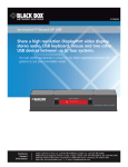
1
KV2004A KV2204A May 2010 KV2304A KV2404A ServSwitch Wizard DVI DL Control up to four computer systems and share BLACK BOX peripherals among them. ® KV2004A supports one video head per channel, KV2204A supports two, KV2304A supports three, and KV2404A supports four. Customer Support Information Order toll-free in the U.S.: Call 877-877-BBOX (outside U.S. call 724-746-5500) • FREE technical support 24 hours a day, 7 days a week: Call 724-746-5500 or fax 724-746-0746 • Mailing address: Black Box Corporation, 1000 Park Drive, Lawrence, PA 15055-1018 • Web site: www.blackbox.com • E-mail: [email protected] ServSwitch Wizard DVI DL Trademarks Used in this Manual Black Box and the Double Diamond logo are registered trademarks, and ServSwitch Wizard is a trademark, of BB Technologies, Inc. Apple and Mac are registered trademarks of Apple Computer, Inc. IBM is a registered trademark of International Business Machines Corporation. Linux is a registered trademark of Linus Torvalds. Windows is a registered trademark of Microsoft Corporation. Sun is a registered trademark of Sun Microsystems, Inc. Unix is a registered trademark of UNIX System Laboratories, Inc. Any other trademarks mentioned in this manual are acknowledged to be the property of the trademark owners. We‘re here to help! If you have any questions about your application or our products, contact Black Box Tech Support at 724-746-5500 or go to blackbox.com and click on “Talk to Black Box.” You’ll be live with one of our technical experts in less than 20 seconds. Page 2 724-746-5500 | blackbox.com FCC and IC RFI Statements Federal Communications Commission and Industry Canada Radio Frequency Interference Statements This equipment generates, uses, and can radiate radio-frequency energy, and if not installed and used properly, that is, in strict accordance with the manufacturer’s instructions, may cause interference to radio communication. It has been tested and found to comply with the limits for a Class A computing device in accordance with the specifications in Subpart B of Part 15 of FCC rules, which are designed to provide reasonable protection against such interference when the equipment is operated in a commercial environment. Operation of this equipment in a residential area is likely to cause interference, in which case the user at his own expense will be required to take whatever measures may be necessary to correct the interference. Changes or modifications not expressly approved by the party responsible for compliance could void the user’s authority to operate the equipment. This digital apparatus does not exceed the Class A limits for radio noise emission from digital apparatus set out in the Radio Interference Regulation of Industry Canada. Le présent appareil numérique n’émet pas de bruits radioélectriques dépassant les limites applicables aux appareils numériques de la classe A prescrites dans le Règlement sur le brouillage radioélectrique publié par Industrie Canada. 724-746-5500 | blackbox.com Page 3 ServSwitch Wizard DVI DL Instrucciones de Seguridad (Normas Oficiales Mexicanas Electrical Safety Statement) 1. Todas las instrucciones de seguridad y operación deberán ser leídas antes de que el aparato eléctrico sea operado. 2. Las instrucciones de seguridad y operación deberán ser guardadas para referencia futura. 3. Todas las advertencias en el aparato eléctrico y en sus instrucciones de operación deben ser respetadas. 4. Todas las instrucciones de operación y uso deben ser seguidas. 5. El aparato eléctrico no deberá ser usado cerca del agua—por ejemplo, cerca de la tina de baño, lavabo, sótano mojado o cerca de una alberca, etc. 6. El aparato eléctrico debe ser usado únicamente con carritos o pedestales que sean recomendados por el fabricante. 7. El aparato eléctrico debe ser montado a la pared o al techo sólo como sea recomendado por el fabricante. 8. Servicio—El usuario no debe intentar dar servicio al equipo eléctrico más allá a lo descrito en las instrucciones de operación. Todo otro servicio deberá ser referido a personal de servicio calificado. 9. El aparato eléctrico debe ser situado de tal manera que su posición no interfiera su uso. La colocación del aparato eléctrico sobre una cama, sofá, alfombra o superficie similar puede bloquea la ventilación, no se debe colocar en libreros o gabinetes que impidan el flujo de aire por los orificios de ventilación. 10. El equipo eléctrico deber ser situado fuera del alcance de fuentes de calor como radiadores, registros de calor, estufas u otros aparatos (incluyendo amplificadores) que producen calor. 11. El aparato eléctrico deberá ser connectado a una fuente de poder sólo del tipo descrito en el instructivo de operación, o como se indique en el aparato. 12. Precaución debe ser tomada de tal manera que la tierra fisica y la polarización del equipo no sea eliminada. 13. Los cables de la fuente de poder deben ser guiados de tal manera que no sean pisados ni pellizcados por objetos colocados sobre o contra ellos, poniendo particular atención a los contactos y receptáculos donde salen del aparato. 14. El equipo eléctrico debe ser limpiado únicamente de acuerdo a las recomendaciones del fabricante. 15. En caso de existir, una antena externa deberá ser localizada lejos de las lineas de energia. 16. El cable de corriente deberá ser desconectado del cuando el equipo no sea usado por un largo periodo de tiempo. 17. Cuidado debe ser tomado de tal manera que objectos liquidos no sean derramados sobre la cubierta u orificios de ventilación. 18. Servicio por personal calificado deberá ser provisto cuando: A: El cable de poder o el contacto ha sido dañado; u B: Objectos han caído o líquido ha sido derramado dentro del aparato; o C: El aparato ha sido expuesto a la lluvia; o D: El aparato parece no operar normalmente o muestra un cambio en su desempeño; o E: El aparato ha sido tirado o su cubierta ha sido dañada. Page 4 724-746-5500 | blackbox.com Table of Contents Table of Contents 1. Specifications ..........................................................................................................................................................................6 2. Overview ..........................................................................................................................................................................8 2.1 Introduction......................................................................................................................................................................8 2.2 Features ..........................................................................................................................................................................8 2.3 What’s Included................................................................................................................................................................9 2.4 Additional Items You May Need.........................................................................................................................................9 2.5 Hardware Description, Single-Head Version (KV2004A).................................................................................................. 10 2.5.1 Front Panel....................................................................................................................................................... 10 2.5.2 Back Panel........................................................................................................................................................ 11 2.6 Hardware Description, Multi-Head Versions (KV2204A, KV2304A, and KV2404A)......................................................... 12 2.6.1 Front Panel....................................................................................................................................................... 12 2.6.2 Back Panel........................................................................................................................................................ 13 3. Installation ........................................................................................................................................................................ 14 3.1 Mounting........................................................................................................................................................................ 14 3.2 Connections.................................................................................................................................................................... 14 3.2.1 User Console.................................................................................................................................................... 14 3.2.2 Computer Systems............................................................................................................................................ 17 3.2.3 Power In Connection........................................................................................................................................ 19 3.2.4 Switching Control by Computer........................................................................................................................20 3.2.5 Synchronizing Multiple Units............................................................................................................................. 21 3.2.6 Managing EDID VIdeo Display Information........................................................................................................22 4. Configuration ........................................................................................................................................................................23 4.1 Using the Configuration Menu........................................................................................................................................23 4.2 General Configuration.....................................................................................................................................................24 4.2.1 Changing Hotkeys............................................................................................................................................24 4.2.2 Mouse Switching..............................................................................................................................................25 4.2.3 Miscellaneous Functions...................................................................................................................................25 4.3 Performing Upgrades......................................................................................................................................................25 5. Operation ........................................................................................................................................................................28 5.1 Selecting a Computer......................................................................................................................................................28 5.1.1 Select a Computer Using the Front Panel..........................................................................................................28 5.1.2 Select a Computer Using Hotkeys.....................................................................................................................29 5.1.3 Select a Computer Using the Mouse Buttons....................................................................................................30 5.2 Autoscanning..................................................................................................................................................................30 Appendix A. What Is True Emulation?.....................................................................................................................................................32 A.1 Enumerated USB Switching..............................................................................................................................................32 A.2 Emulated USB Switching..................................................................................................................................................32 A.3 True Emulation................................................................................................................................................................32 Appendix B. Default EDID Video Modes..................................................................................................................................................34 Appendix C. Cable Pinouts.....................................................................................................................................................................35 Appendix D. Safety Information..............................................................................................................................................................36 724-746-5500 | blackbox.com Page 5 ServSwitch Wizard DVI DL 1. Specifications Approvals: CE, FCC Hardware Compatibility: All computers with USB interfaces Software Compatibility: Operates with all known software and operating systems including Windows®, Linux®, Unix®, BSD, all Sun® OS, all Mac® OS, NetWare®, etc. Connectors: KV2004A: User Console: (1) DVI-I F (dual-link support), (2) USB Type A F (for keyboard and mouse, emulated), (2) USB Type A F (for USB 2.0 peripheral support, not emulated), (1) 3.5-mm audio jack; Computer Channels: (4) DVI-I F (dual-link support), (4) USB Type B F, (4) 3.5-mm stereo jack; Other: (1) barrel power jack, (1) RJ-45, 10P10C options port for serial upgrade or RS-232 switching; KV2204A: User Console: (2) DVI-I F (dual-link support), (2) USB Type A female (for keyboard and mouse, emulated), (2) USB Type A F (for USB 2.0 peripheral support, not emulated); (1) 3.5-mm stereo jack; Computer Channels: Video: (8) DVI-I F (dual-link support); (4) USB Type B F; (4) 3.5-mm stereo jack; Other: (1) barrel power jack, (1) RJ-45, 10P10C options port for serial upgrade or RS-232 switching; KV2304A: User Console: (3) DVI-I F (dual-link support). (2) USB Type A F (for keyboard and mouse, emulated), (2) USB Type A F (for USB 2.0 peripheral support, not emulated), (1) 3.5-mm stereo jack; Switched USB: (2) USB Type A (USB 2.0, emulated); Computer channels: (12) DVI-I F (dual-link support), (4) USB Type B F, (4) 3.5-mm stereo jacks, Other: (1) barrel power jack, (1) RJ-45, 10P10C options port for serial upgrade or RS-232 switching; KV2404A: User Console: (4) DVI-I F (dual-link support), (2) USB Type A F (for keyboard and mouse, emulated), (2) USB Type A female (for USB 2.0 peripheral support, not emulated, (1) 3.5-mm stereo jack; Computer Channels: (16) DVI-I F (dual-link support), (4) USB Type B F, (4) 3.5-mm stereo jack; Other: (1) barrel power jack, (1) RJ-45, 10P10C options port for serial upgrade or RS-232 switching Operating Temperature: 32 to 104° F (0 to 40° C) Page 6 724-746-5500 | blackbox.com Chapter 1: Specifications Power: 2.5-mm DC jack (power adapter included), Input: 100–240 VAC, 50/60 Hz, Output: KV2004A: 5-VDC, 2.5-A; KV2204A, KV2304A, KV2404A: 5-VDC, 4-A; Power consumption: KV2004A: 12.5 watts, KV2204A, KV2304A, KV2404A: 20 watts Size: KV2004A: 1.73"H (1U) x 9.21"W x 4.72"D (4.39 x 23.39 x 11.99 cm); KV2204A, KV2304A, KV2404A: 4.375"H (2.5U) x 9.21"W x 4.72"D (11.13 x 23.39 x 11.99 cm) Weight: KV2004A: 1.87 lb. (0.85 kg); KV2204A: 2 lb. (0.91 kg) KV2304A: 2.1 lb. (0.95 kg); KV2404A: 2.2 lb. (1 kg) 724-746-5500 | blackbox.com Page 7 ServSwitch Wizard DVI DL 2. Overview 2.1 Introduction There are four versions of the four-way ServSwitch Wizard™ DVI DL, each of which allows a single operator to control up to four computer systems and share peripherals among them in a very flexible manner. The KV2004A can support one video head per channel, whereas the slightly larger KV2204A, KV2304A, and KV2404A units support two, three, and four video heads per channel, respectively. Thanks to high quality, efficient switching technology, each video head can support dual link digital video at up to 530 Mpixels per second. In addition to the video performance, these units offer more than just straight switching between four systems. The KVM, speakers, and two separate USB devices attached to the Wizard DVI DL units can either be switched in unison, or you can share your peripherals between any of the systems to suit your current tasks. For instance, you could be creating e-mails on one system, listening to a soundtrack from another while a third is sending documents to your printer, and a fourth is performing another task with a different USB peripheral. The ServSwitch Wizard DVI DL front panels make it easy to control which peripherals should connect to each system. The ServSwitch Wizard DVI DL units feature True Emulation (see Appendix A), which ensures that the full characteristics of the connected keyboard and mouse are passed to every system. 2.2 Features 2SPKKVMCOMPUTERKVMSPKUSB1USB2MODEWizardDVIDL Multiscreen Versions The ServSwitch Wizard DVI DL includes separate models to support one, two, three, or four video heads per channel. Multiple Switching The attached peripheral devices can be switched collectively to any computer system, or they can be linked to separate systems to achieve multiple tasks in parallel. Multiple switching can be controlled from the front-panel buttons, keyboard hotkeys, mouse buttons, or optional 4-button key switch unit. This unit does not support On-Screen Display (OSD) control. Digital and Analog Video The ServSwitch Wizard DVI DL uses DVI-I (Integrated) connectors throughout so that DVI digital or VGA analog video may be used (VGA requires the use of suitable adapter cables). Do not mix and match analog and digital inputs at the same time. True Emulation Earlier USB KVM switches relied upon standard keyboard and mouse templates to tell each computer system how to deal with the connected peripherals. The ServSwitch Wizard DVI DL range gathers the true identities of the connected keyboard and mouse and presents those “real” profiles concurrently to every system. Thus, specialized keyboards and mice can be fully supported. Intelligent Display Information The ServSwitch Wizard DVI DL uses an EDID emulation feature to ensure that all computers are supplied with the correct information about each connected video display. It supports hybrid DDC routing (DDC is emulated when not selected and switched through when selected). This enables DDC-CI (DDC Command Interface) to be supported. Page 8 724-746-5500 | blackbox.com Chapter 2: Overview USB Remote Wakeup The ServSwitch Wizard fully supports the USB Remote Wakeup feature. Any connected computer can go into sleep mode and be awakened (when its channel is selected) as soon as you press a key or move the mouse. Note that the computer and peripherals must also support the USB Remote Wakeup feature. Figure 2-1. Typical application. 2.3 What’s Included Your package should contain the following items. If anything is missing or damaged, contact Black Box Technical Support at 724-746-5500 or [email protected]. • ServSwitch Wizard DVI DL unit (KV2004A) or ServSwitch Wizard DVI DL Multihead unit (KV2204A, KV2304A, or KV2304A) • 12.5-watt or 20-watt power adapter and country-specific power cord • (4) self-adhesive feet • CD-ROM containing this user’s manual in PDF format 2.4 Additional Items You May Need • DVI to VGA adapter (FA462) • Single-link DVI-D to DVI-D video cable (EVNDVI02-XXXX) • Combined dual-link DVI-I and USB (USB Type A to B) cable (EHN900024U-XXXX) • Audio cable (EJ110-XXXX) • Flash upgrade adapter plus standard 9.6-ft. (3-m) patch lead • For KV2004A: (2) rackmount brackets and (4) screws (RMK2007); For multihead versions: call tech support at 724-746-5500 724-746-5500 | blackbox.com Page 9 ServSwitch Wizard DVI DL 2.5 Hardware Description, Single-Head Version (KV2004A) 2.5.1 Front Panel Figure 2-2 shows the front panel of the ServSwitch Wizard DVI DL. Table 2-1 describes its components. 2 1 3 Figure 2-2. Front panel. Table 2-1. Front-panel components. Number Component Description 1 COMPUTER button Press to change to the next computer channel. 2 IndicatorsThe four indicators (KVM, SPK, USB1, USB2) show which peripherals are switched to the current computer channel or (as you begin pressing the MODE button) the peripherals that will be switched during the next press(es) of the COMPUTER button. The seven-segment numeric display indicates the computer channel that is currently active. 3 MODE buttonPress to determine which peripherals should be switched to another computer channel (will occur when you press the COMPUTER button). Page 10 724-746-5500 | blackbox.com Chapter 2: Overview 2.5.2 Back Panel Figure 2-3 shows the back panel of the ServSwitch Wizard DVI DL. Table 2-2 describes its components. 4 5 6 11 11 11 7 9 8 10 9 10 9 10 11 9 10 12 Figure 2-3. Back panel. Table 2-2. Back panel components. Number Component Description 4 Barrel connector Power input or power supply connects here. 5 (2) USB Type A connectors Connect the console’s USB keyboard and mouse to these connectors. 6 3.5-mm RCA connector User console audio port: Connect optional speakers to this connector. 7 DVI-I connector Connect the console’s DVI-I monitor to this port. 8 RJ-45 port*Options port: This 10p10c port is used to update the internal firmware when necessary by connectng to a computer. 9 (4) USB Type B connectors 10 (4) 3.5-mm RCA connectorsComputer audio port: connect to the computer’s audio output socket, or sound card. 11 (4) DVI-I connectors Connect to the computer’s video output or graphics card. 12 (2) USB Type A connectors Connect to USB 2.0 peripheral devices. Connect to the computer’s USB port. *NOTE: The OPTIONS port uses a 10p10c socket, which can accommodate both 10p10c connectors as well as the much more common 8p8c connectors, which are used on Ethernet leads and patch cables. The pin-outs for both types of connectors are listed in Appendix C. 724-746-5500 | blackbox.com Page 11 ServSwitch Wizard DVI DL 2.6 Hardware Description, Multihead Versions (KV2204A, KV2304A, and KV2404A) 2.6.1 Front Panel Figure 2-4 shows the front panel of the ServSwitch Wizard DVI DL, multihead versions. Table 2-2 describes its components. 1 2 3 Figure 2-4. Front panel. Table 2-3. Front-panel components. Number Component Description 1 COMPUTER button Press to change to the next computer channel. 2 IndicatorsThe four indicators (KVM, SPK, USB1, USB2) show which peripherals are switched to the current computer channel or (as you begin pressing the MODE button) the peripherals that will be switched during the next press(es) of the COMPUTER button. NOTE: The multiscreen versions also include four additional indicators, labeled V1 to V4, that show the video channels being switched. The seven-segment numeric display indicates the computer channel that is currently active. 3 Page 12 MODE buttonPress to determine which peripherals should be switched to another computer channel (will occur when you press the COMPUTER button). 724-746-5500 | blackbox.com Chapter 2: Overview 2.6.2 Back Panel Figure 2-5 shows the back panel of the ServSwitch Wizard DVI DL. Table 2-4 describes its components. 11 7 4 5 8 6 9 10 9 11 11 11 10 9 10 9 10 12 Figure 2-5. Back panel. Table 2-4. Back panel components. Number Component Description 4 Barrel connector Power input or power supply connects here. 5 (2) USB Type A connectors Connect the console’s USB keyboard and mouse to these connectors. 6 3.5-mm RCA connector User console audio port: Connect optional speakers to this connector. 7 (4) DVI-I connectors Connect the console’s DVI-I monitor to this port. 8 RJ-45 portOptions port: This 10p10c port is used to update the internal firmware when necessary by connectng to a computer. 9 (4) USB Type B connectors 10 (4) 3.5-mm RCA connectorsComputer audio port: connect to the computer’s audio output socket, or sound card. 11 (16) DVI-I connectorsConnect to the computer’s video output or graphics card. 12 (2) USB Type A connectors Connect to the computer’s USB port. Connect to USB 2.0 peripheral devices. 724-746-5500 | blackbox.com Page 13 ServSwitch Wizard DVI DL 3. Installation 3.1 Mounting There are two main mounting methods: • Via the (4) supplied self-adhesive rubber feet • Via optional rackmount brackets (RMK4007 for KV2004A; Call Tech Support for KV2204A, KV2304A, or KV2404A) Rack brackets: The optional brackets (plus four screws), enable the unit to be secured within a standard rack slot. See Figure 3-1. Figure 3-1. Rackmount brackets. NOTE: Both the Wizard DVI DL unit and its power supply generate heat when in operation and will become warm to the touch. Do not enclose them or place them in locations where air cannot circulate to cool the equipment. Do not operate the equipment in ambient temperatures exceeding 104° F (40° C). Do not place the products in contact with equipment whose surface temperature exceeds 104° F (40° C). 3.2 Connections Connections do not need to be carried out in the order given within this guide, however, where possible connect the power as a final step. 3.2.1 User Console The ports on the user console side of the switch are where you attach the peripherals that will be shared between the computer systems. Make sure that power is disconnected from the unit. To connect peripherals to the user console: 1. Position your peripheral devices close together so their cables will easily reach. 2. Keyboard and mouse: Attach the leads from your USB keyboard and mouse to the USB connectors on the switch that are specifically labeled with keyboard and mouse symbols. The keyboard and mouse will operate in any of the USB connectors, however, True Emulation is not available on connectors labeled USB1 or USB2. See Figure 3-2. Page 14 724-746-5500 | blackbox.com Chapter 3: Installation From USB keyboard and mouse Figure 3-2. Connecting the keyboard/mouse to the user console. NOTE: The unit’s True Emulation feature will read the full characteristics of the keyboard and mouse and will present those to each connected computer concurrently. This ensures that specialized keyboards and mice are fully supported. 3. USB devices. Where required, attach the leads from your USB peripherals to the USB connectors labeled USB1 and USB2. See Figure 3-3. From USB peripherals Figure 3-3. Connecting USB peripherals to the user console. 4. Video monitor(s): DVI-I (integrated) video ports are used throughout to enable digital DVI and/or VGA analog (via adapter cables) signals to be switched, as required. 724-746-5500 | blackbox.com Page 15 ServSwitch Wizard DVI DL Single-head units: Attach the lead from the video monitor to the DVI-I connector of the user console area. See Figure 3-4. From video monitor Figure 3-4. Connecting a video monitor to the user console. NOTE: During initial powerup, the ServSwitch Wizard DVI DL unit will attempt to read the EDID information from the connected display(s). See Section 3.2.6 for details. Some displays require the EDID function to be encoded manuallly (see Section 4.2.3 for details). Multihead units: Attach the lead from each video monitor to a DVI-I connector of the user console area. See Figure 3-5. NOTE: On the rear panel of the unit, the connectors at each horizontal level (V1 to V4) will be switched through to the user console DVI-I connector that is at the same level. From video monitors Figure 3-5. Connecting four video monitors to the user console. Page 16 724-746-5500 | blackbox.com Chapter 3: Installation 5. Audio: Where required, connect the lead from your speakers to the audio connector. See Figure 3-6. From speakers Figure 3-6. Connecting speakers to the user console. 3.2.2 Computer Systems Each computer system is connected to the Wizard DVI DL unit using up to three cables. To connect a computer system: 1. Make sure that power is disconnected from the Wizard DVI DL unit and the system to be connected. 2. Use a USB cable (Type A to Type B) to link a USB port on the computer system to the USB port of the required channel on the rear of the unit. 3. If required, use a stereo audio link cable (3.5-mm jacks at either end) to link the speaker port on the computer system to the audio port of the required channel on the rear of the unit. See Figure 3-7. From the speaker port on the computer Figure 3-7. Connecting a computer unit to the Wizard DVI DL unit. 724-746-5500 | blackbox.com Page 17 ServSwitch Wizard DVI DL 4. Single-head units: Use a DVI cable or a VGA to DVI-I adapter cable (if using analog signals) to link the video output of the computer’s graphic port to the DVI-I port of the required channel on the rear of the unit. See Figure 3-8. From the video port on the computer Figure 3-8. Connecting the video output to the DVI-I port. NOTE: A combined DVI-D and USB (Type A to B) cable is also available for linking computers to the Wizard DVI DL unit. During initial powerup, the Wizard DVI DL unit will attempt to read the EDID information from the connected display(s). See Section 3.2.6 for details. Multihead units: Use DVI or VGA to DVI-I adapter cables (if using analog signals) to link the video outputs of each computer to the DVI-I ports on the rear of the unit (see Figure 3-9 and the note below). Figure 3-9. Connecting mutliple video outputs to the DVI-I ports. NOTE: On the rear panel of the unit, connectors belonging to the same channel are stacked vertically. The connectors at each horizontal level (V1 to V4) will be switched through to the user console DVI-I connector which is at the same level. See Figure 3-10. Page 18 724-746-5500 | blackbox.com Chapter 3: Installation Figure 3-10. Vertically stacked connectors linked to the same channels. 3.2.3 Power In Connection The Wizard DVI DL unit is supplied with either a 12.5 W (single-head version) or 20 W (multihead versions) power adapter. There is no on/off switch on the unit, so operation begins as soon as the power adapter is connected. To connect the power adapter: 1. Attach the output lead from the power adapter to the 5V socket on the rear panel of the unit. See Figure 3-11. Figure 3-11. Connecting the power adapter. 724-746-5500 | blackbox.com Page 19 ServSwitch Wizard DVI DL 2. Connect the IEC connector of the supplied country-specific power lead to the power adapter’s connector. See Figure 3-12. Figure 3-12. Connecting the power lead to the power adapter’s connector. 3. Connect the power lead to a nearby power outlet. NOTE: Both the unit and its power supply generate heat when in operation and will become warm to the touch. Do not enclose them or place them in locations where air cannot circulate to cool the equipment. Do not operate the equipment in ambient temperatures exceeding 104° F (40° C). Do not place the products in contact with equipment whose surface temperature exceeds 104° F (40° C). 3.2.4 Switching Control by Computer The OPTIONS port featured on every ServSwitch Wizard DVI DL enables an external serial input, typically from a computer, to control the selection of the various channels. For more details about the necessary cable, see Appendix C. Upon receipt of the correct code, the ServSwitch Wizard DVI DL switches immediately to the appropriate channel. Connecting a computer for remote control: The cable link from the computer needs to connect the transmit (TXD) line of the computer to the receive (RXD) input of the Wizard DVI DL and also link the ground terminals (GND) of the two devices. See Appendix C for details. To connect a computer remote control: 1. Insert the 8p8c or 10p10c connector of the cable to the OPTIONS port on the rear panel of the unit. Figure 3-13. Connecting a computer remote control. 2. Connect the other end of the cable to a vacant serial port on the computer. Page 20 724-746-5500 | blackbox.com Chapter 3: Installation Serial port parameter settings: Make sure that the chosen serial port is configured as follows: • Baud rate: 1200 • Data bits: 8 • Stop bit: 1 • Parity: None For channel selection codes, see Table 3-1. Table 3-1. Channel selection codes. Number ASCII Hex Decimal Channel 1 1 0x31 49 Channel 2 2 0x32 50 Channel 3 3 0x33 51 Channel 4 4 0x34 52 3.2.5 Synchronizing Multiple Units ServSwitch Wizard DVI DL units can be connected together so that they operate in a synchronized manner. Thus, two KV2004A units can be made to switch two video heads in a similar manner to an KV2204A. Additonally, two KV2204A (dual) units could be made to resemble an KV2404A (quad), while two KV2404A units could be combined in order to switch up to eight video heads simultaneously. Whenever a ServSwitch Wizard DVI DL channel is switched, it sends an RS-232 command out on its serial interface (marked OPTIONS on the rear panel). A ServSwitch Wizard DVI DL will switch its channel if it receives the same command on its serial interface. Consequently, by linking the serial interfaces, a master unit may be made to automatically switch one or more slave units as shown in Figure 3-14. Note that the synchronization cable deliberately does not have the transmit pin of the Slave End connector linked to the receive pin of the Master End connector. To do so would cause the Slave unit to be able to switch the Master unit. This would setup an endless cyclical switching sequence that would prevent the ServSwitch Wizard DVI DL devices from operating correctly. For more details about the serial synchronization cables, see Appendix C. Serial synchronization cable Slave ServSwitch Wizard DVI DL Master ServSwitch Wizard DVI DL Slave monitor Slave moni- Master monitor Computers fitted with multiple video heads Figure 3-14. Synchronizing multiple units. 724-746-5500 | blackbox.com Page 21 ServSwitch Wizard DVI DL 3.2.6 Managing EDID Video Display Information Whenever a ServSwitch Wizard DVI DL unit is powered on (or when the option is selected from the configuration menu), it will interrogate the connected monitor(s) to determine whether EDID (Extended Display Identification Data) information is available. If EDID information is available, it will be copied and used; otherwise a default set of data, stored within the ServSwitch Wizard DVI DL, will be substituted. The ServSwitch Wizard DVI DL units use the EDID emulation feature to ensure that the collected EDID information (up to two pages) is correctly supplied to every connected computer. In the multihead (KV2204A, KV2304A and KV2404A) units, the EDID emulation and hybrid DDC features ensure that separate EDID data from each video display will be distributed through to the appropriate video adapters within each computer. Figure 3-15. Multiscreen configuration. Refreshing EDID information during use: You can refresh the EDID information from the connected monitor(s) without the need to power cycle the Wizard DVI DL. To refresh EDID information during use: 1. Enter the Configuration menu. 2. Press the F key to enter the Functions menu. 3. Press 2 and then the Enter key. 4. Press E and then Enter to exit the menu. Page 22 724-746-5500 | blackbox.com Chapter 4: Configuration 4. Configuration 4.1 Using the Configuration Menu The configuration mode allows you to determine numerous aspects of the Wizard DVI DL unit capabilities. To use the configuration menu: During normal use, the seven-segment display on the front panel shows the number of the currently selected computer channel. From this condition, enter configuration mode as follows: 1. Press and hold the front-panel COMPUTER button for roughly five seconds. The display will show: C 2. On the keyboard, press the letter key for the required menu section, for example: S The display will show the pressed letter, for example: S 3. Press the number of the required setting, for example: 4 The display will show the pressed number, for example: 4 4. Press Enter to accept the setting and return to the main menu section. The display will show: C 5. You can now continue with your next configuration change (go back to Step 2), or exit from the configuration menu (see below). To exit the configuration menu and save changes: • Press E and then press Enter to exit and save changes. To exit the configuration menu without saving: • Press either of the front-panel buttons. Table 4-1. Configuration menu. NOTE: You can press the Esc key at any point to exit from an option and return to the main menu ( [ ) section. Letter Number F Description Enter the Functions menu 1 Show current firmware version 2 Refresh EDID information from the connected video display 3 Reset the configuration to the factory defaults (r is displayed momentarily) H Enter the Hotkey menu 1 Ctrl + Alt 2 Ctrl +Shift 3 Alt + Shift 4 Right Alt 5 Alt 6 Left-Ctrl + Alt 7 Right-Ctrl + Alt 8 Hotkeys disabled NOTE: The Configuration menu is continued on the next page. 724-746-5500 | blackbox.com Page 23 ServSwitch Wizard DVI DL Table 4-1 (Continued). Configuration menu. Letter Number S Description Enter the Switch Mode menu 1 All 2 KVM + speaker 3 KVM only 4 Speaker only 5 USB 1 only 6 USB 2 only T Enter the Autoscan Time Delay menu 1 Autoscan disabled 2 2 seconds 3 5 seconds 4 7 seconds 5 15 seconds 6 30 seconds 7 1 minute 8 5 minutes U Enter the User Preferences menu 1 Enable mouse switching 2 Disable mouse switching 3 Cycle all ports (when using “Hotkey + Tab” or “Autoscan”) 4 Cycle only active ports (when using “Hotkey + Tab” or “Autoscan”) 4.2 General Configuration 4.2.1 Changing Hotkeys ServSwitch Wizard DVI DL units use Ctrl and Alt as their standard hotkeys. These can be changed if they clash with other software or hardware within the installation. To change the hotkeys: 1. Enter the Configuration menu. 2. Press H to enter the Hotkey menu and then press either: 1 to choose Ctrl + Alt 5 to choose Alt 2 to choose Ctrl + Shift 6 to choose Left-Ctrl + Alt 3 to choose Alt + Shift 7 to choose Right-Ctrl + Alt 4 to choose Right Alt 8 to disable the Hotkeys Page 24 724-746-5500 | blackbox.com Chapter 4: Configuration 4.2.2 Mouse Switching You can enable or disable mouse switching to suit your installation requirements. To enable/disable mouse switching: 1. Enter the Configuration menu. 2. Press U to enter the User Preferences menu and then press either: 1 to Enable mouse switching 2 to Disable mouse switching 3. Press Enter to accept the setting and return to the main menu section. 4. Press E and then Enter to exit the menu and save changes. 4.2.3 Miscellaneous Functions To refresh EDID information from the monitor: 1. Enter the Configuration menu. 2. Press F to enter the Functions menu 3. Press 2 and then Enter. 4. Press E and then Enter to exit the menu and save changes. To reset configuration to factory defaults: 1. Enter the Configuration menu. 2 Press F to enter the Functions menu. 3. Press 8 and then Enter. The display will show r momentarily. 4. Press E and then Enter to exit the menu and save changes. To show the current firmware version: 1. Enter the Configuration menu. 2. Press F to enter the Functions menu 3. Press 1 and then Enter. The display will blank for a short while and then the major number of the firmware revision will be shown. The display will blank again and then show the first digit of the minor number. Following another blank, the second digit of the minor number will be displayed, for example: <blank> 1 <blank> 0 <blank> 2 <blank> equals v1.02 4. Press E and then Enter to exit the menu and save changes. 4.3 Performing Upgrades The The Wizard DVI DL unit is fully upgradable via Flash upgrade. Such upgrades require a Windows® based computer system to be linked via the OPTIONS port. Items required to perform an upgrade include: • Optional upgrade cable (see Appendix C for pinout specifications) • A Windows based upgrade computer with an RS-232 serial port • The latest version of the KVM Firmware Uploader and firmware files for the ServSwitch Wizard DVI DL unit (available from Black Box Technical Support—call 724-746-5500 or send an e-mail to [email protected]) 724-746-5500 | blackbox.com Page 25 ServSwitch Wizard DVI DL To use the KVM Firmware Uploader utility: 1. Obtain and run the KVM Firmware Uploader. (Contact Black Box Technical Support at 724-746-5500 or [email protected].) Download the latest ServSwitch Wizard DVI DL unit KVM Firmware Uploader from Black Box Technical Support and install it on a Windows based upgrade computer that will be connected to the ServSwitch Wizard DVI DL unit. The files are supplied as a compressed ZIP file. Decompress the ZIP file with an appropriate tool such as WinZip (www.winzip.com) and copy all contained files to the same folder on the upgrade computer. 2. Power off the ServSwitch Wizard DVI DL unit. Remove the power supply plug from the rear panel of the unit. 3. Connect the upgrade computer to the ServSwitch Wizard DVI DL unit. Connect the serial port of the upgrade computer to the OPTIONS port on the rear panel of the unit using the optional upgrade cable. 4. Invoke upgrade mode. While powering on or when already powered: Press and hold the COMPUTER and MODE buttons (for up to ten seconds) until the numeric indicator shows ‘U’. 5. Run the KVM Firmware Uploader utility. From that folder, select the KVMUploader icon to run the upgrade utility. The KVM Firmware Uploader dialog will be displayed as shown in Figure 4-1. Figure 4-1. KVM Firmware Uploader utility screen. 6. Query the ServSwitch Wizard DVI DL unit. Click the “Query Unit” button to confirm that communication is possible with the ServSwitch Wizard DVI DL unit and to establish its firmware details. If successful, the “Unit connected” field should show the name of the ServSwitch Wizard DVI DL unit and the current firmware will also be listed. If the application cannot contact the ServSwitch Wizard DVI DL unit, re-check the connection cable and click the “Advanced...” button to check that the correct serial port is being used. Change the serial port within the Advanced... section, if necessary. NOTE: There is no need to adjust the computer’s serial port settings because the application will do this automatically. 7. Select the upgrade file you want to use. From the main KVM Firmware Uploader dialog, click on the the “Browse...” button and select the upgrade file: DVIDL4_xxx.txt where xxx is the firmware version. The upgrade file details will be displayed within the dialog. Page 26 724-746-5500 | blackbox.com Chapter 4: Configuration IMPORTANT: Check that the “Intended Target Units” field matches the “Unit connected” field. If these fields do not match, then you may have an incorrect upgrade file, and you should check with Black Box Technical Support before proceeding. Check also that the “New firmware version” is greater than the “Current firmware version.” See Figure 4-2. Check that the “Intended Target Units” field matches the “Unit connected” field. Check also that the “New firmware version” is greater than the “Current firmware version.” Figure 4-2. Selecting the upgrade file from the KVM Firmware Uploader window. 8. Begin the upgrade. To begin the upgrade process, click the “Upload Now” button. The progress will be shown within the dialog. If you decide not to continue with the upload at any stage, click the “Abort” button; response to this is usually immediate, however, during an erase command, the upload will not be aborted until the erase is complete (this may take a few seconds). 9. Cycle the power. Disconnect the power. When the power is re-applied, the ServSwitch Wizard DVI DL unit will operate using the new firmware. Issues to consider when performing flash upgrades: The upgrade program rewrites the internal firmware code. If the upgrade process is interrupted, then the unit will have invalid code and will not be able to operate. It is therefore good practice to make sure that the upgrade process is always fully completed. A partial or failed upgrade may be rectified by performing another upgrade. WARNING: Running faulty or partially upgraded code may have unpredictable results and may damage your ServSwitch Wizard DVI DL unit or computing equipment. 724-746-5500 | blackbox.com Page 27 ServSwitch Wizard DVI DL 5. Operation 5.1 Selecting a Computer There are three main ways to switch the common peripherals to specific computer channels: • Using the front-panel controls • Using hotkeys • Using mouse button presses 5.1.1 Select a Computer Using the Front Panel The front panel allows you to determine how the various peripherals are switched to one or more computer channels. Indicates the number of the currently selected computer The KVM, SPK, USB1, and USB2 indicators show which peripherals are switched to the current computer channel OR (as you begin pressing the MODE button) the peripherals that will be switched during the next press(es) of the COMPUTER button. Multihead models only: The V1 Use this button to choose to V4 indicators show which video the next required computer. monitors are switched to the current computer channel. Figure 5-1. Front-panel buttons. 1. Optional: If you need to selectively switch some of your peripherals, press the “MODE” button repeatedly to change the switching mode (It toggles through the different selections.): Press the “MODE” button until the “KVM,” “SPK,” “USB1,” “USB2” LEDs are all lit to switch all peripherals together. Press the “MODE” button until the “KVM” and “SPK” LEDs are both lit to switch keyboard, video, mouse, and speakers. Press the “MODE” button until the “KVM” LED is lit to switch only the keyboard, video, and mouse. Press the “MODE” button until the “SPK” LD is lit to switch only the speakers. Press the “MODE” button until the “USB1” LED is lit to switch only USB peripheral 1. Press the “MODE” button until the “USB2” LED is lit to switch only USB peripheral 2. NOTE: If an indicator flashes, it signifies that the respective peripheral is currently switched to another computer channel. 2. Press the “COMPUTER” button repeatedly to select the required computer channel. Page 28 724-746-5500 | blackbox.com Chapter 5: Operation 5.1.2 Selecting a Computer Using Hotkeys Using hotkey combinations, you can quickly switch the keyboard, video monitor(s), mouse. speakers. and USB peripherals to any computer channel. The Ctrl and Alt keys when pressed in combination are called ”hotkeys,“ and they signal to the ServSwitch Wizard DVI DL unit that you want to control it, rather than the computer. However, if these particular hotkeys clash with another device or program, you can change them to a different combination within the Configuration menu. There are two main ways to use hotkeys: Standard and Additional. Standard hotkey press combinations: The standard hotkey press combinations enable you to change channels with the minimum of key presses: 1. Simultaneously press and hold Ctrl and Alt (or other hotkeys, if altered). 2. While still holding Ctrl and Alt, press the number key of the required channel address (or the TAB key), then release all the keys. NOTE: The numbers on your keyboard’s numeric keypad are not valid, use only the numeral keys above the QWERTY section. The ports (KVM, audio, and/or USB) that are switched using this method depend upon the switching mode that is currently set using the front-panel buttons (as described in Section 5.1.1). The range of standard hotkey combinations is as follows: NOTE: If your hotkeys have been changed, substitute them for the examples given here. Ctrl + Alt + 1 Selects channel 1 Ctrl + Alt + 2 Selects channel 2 Ctrl + Alt + 3 Selects channel 3 Ctrl + Alt + 4 Selects channel 4 Ctrl + Alt + Tab Isolates the user console from all channels. Selects the next channel. Choosing which computers are accessed when using hotkeys +tab: The computer channels that are selected when you use the hotkeys + tab (or mouse buttons/autoscan) are determined by a setting within the Configuration menu: 1. Enter the Configuration menu. 2. Press U and then press either: 7 to choose Cycle all ports, or 8 to choose Cycle only active ports 3. Press Enter to accept the setting and return to the main menu section. 4. Press E and then Enter to exit the menu and save changes. Additional hotkey press combinations: In addition to the standard hotkey press combinations (shown above), you can also add additional keypresses to determine which peripherals are switched: 1. Simultaneously press and hold Ctrl + Alt, and hold while pressing and releasing a command key: A to switch all peripherals S to switch only the speakers K to switch only the keyboard, video, and mouse U to switch only USB1 and USB2 2. Press and release the required channel number (1 to 4) using only the keys above the QWERTY section). 3. Release Ctrl and Alt. 724-746-5500 | blackbox.com Page 29 ServSwitch Wizard DVI DL The appropriate peripherals will change to the chosen channel. NOTE: Regardless of which peripherals were switched, the front-panel indicators will continue to show the switching mode that was last determined using the front-panel controls. 5.1.3 Selecting a Computer Using the Mouse Buttons Using the mouse buttons, you can quickly switch the keyboard, mouse, video monitor(s), speakers and/or USB peripherals to any computer channel. NOTE: These procedures only work with three-button or IntelliMouse devices and only if the “Mouse Switching”option is enabled. To select a computer using the mouse buttons: 1. Hold down the middle button (or scroll wheel) of the mouse. 2. Click the left mouse button to increase the channel number or click the right mouse button to decrease the channel. When you reach the correct channel, release the middle button. When using this method of switching: • The computer channels that are selected depend upon the configuration menu setting. • The ports (KVM, audio, and/or USB) that are switched using this method depend upon the switching mode that is currently set using the front-panel buttons. Choosing which computers are accessed when using mouse buttons: The computer channels that are selected when you use the mouse buttons (or hotkeys + tab/autoscan) are determined by a setting within the Configuration menu: 1. Enter the Configuration menu. 2. Press U and then press either: 7 to choose Cycle all ports, or 8 to choose Cycle only active ports 3. Press Enter to accept the setting and return to the main menu section. 4. Press E and then Enter to exit the menu and save changes. 5.2 Autoscanning When enabled, the autoscan mode switches between the connected computers in sequence. Use this to sample activity among the connected computers. Two scanning modes are available: • Cycle all ports: This mode selects, in turn, each connected computer. Use this mode with care (see the CAUTION below). To prepare for this autoscan mode, choose within the configuration menu as described on the next page. • Cycle only active ports: Only computer ports where an active computer is detected will be viewed. This mode keeps blank screens from being displayed and helps to prevent the viewing monitor from entering a power-down state on every scan cycle. dditionally, when this mode is selected, whenever you use either the mouse buttons or hotkeys + tab to change channels, A only computers that are active will be selected. To prepare for this autoscan mode, choose within the configuration menu as described on the next page. CAUTION: Many monitors are fitted with automatic power saving relays that switch off after a few seconds when connected to an inactive computer. If you are using this type of monitor, do not use the “Cycle all port” mode. Continously switching the monitor’s relay on and off will eventually damage the monitor. Page 30 724-746-5500 | blackbox.com Chapter 5: Operation Seven autoscan periods are available (the time spent viewing each computer) ranging from 2 seconds to 5 minutes. To select the autoscan period, choose T and then 2 to 8 within the configuration menu as described below. To start autoscanning mode, press Ctrl + Alt + X on the keyboard. To select an autoscan mode: 1. Enter the Configuration menu. 2. Press U and then press either: 7 to choose Cycle all ports, or 8 to choose Cycle only active ports 3. Press Enter to accept the setting and return to the main menu section. 4. Press E and then Enter to exit the menu and save changes. NOTE: The setting of this option also affects which computers are visited when the channel is changed using the mouse buttons or hotkey + tab. To select an autoscan period: 1. Enter the Configuration menu. 2. Press T and then press either: 1 to choose Autoscan disabled, 2 to choose 2 seconds, 3 to choose 5 seconds, 4 to choose 7 seconds, 5 to choose 15 seconds, 6 to choose 30 seconds, 7 to choose 1 minute, or 8 to choose 5 minutes. 3. Press Enter to accept the setting and return to the main menu section. 4. Press E and then Enter to exit the menu and save changes. To start autoscanning: • On the keyboard, press Ctrl + Alt + X. NOTES: Using autoscanning, mouse switching, and hotkey + tab disables interactivity between computers. D uring autoscanning, only the KVM and speaker ports are switched to each visited computer channel. The two USB device ports remain connected to their currently selected channels. To stop autoscanning: You can stop the autoscanning process in either of the following ways: • Press the COMPUTER button on the front panel, or • Select a specific channel using the hotkeys + channel number. 724-746-5500 | blackbox.com Page 31 ServSwitch Wizard DVI DL Appendix A. What Is True Emulation? True Emulation represents a significant breakthrough in sharing USB devices between two or more computer systems. Until this point, the problem has been how to create a USB switch that provides all the following: • Quick, transparent, and reliable switching, • Accurate representation of the connected USB keyboard and mouse, • Switching control via the connected USB keyboard and/or mouse. The difficulty in achieving all the above requirements has been because of the complexity of the USB standard. This has led to various problems that have produced a number of possible solutions. A.1 Enumerated USB Switching The earliest attempts to switch USB devices applied a relatively “hands off” approach. Enumerated USB switches are the electronic equivalent of those old mechanical KVM switches with a large knob on the front. Enumerated switches are so called because a connected USB device will be required to perform a full initiation (a process called Enumeration) every time it is switched; just as if you had pulled out the plug and then reconnected it. Enumerated switches simply pass all signals straight through between the USB device and the computer, they do not attempt to interpret any data. For most devices, this offers an advantage because the switch just leaves them to get on with their jobs without any interference or any hit on performance. However, it means that a USB keyboard or mouse cannot be used to control the switching process—a quick and simple control method expected by most users. Switching reliability is also an issue that has plagued enumerated switches, especially when used with certain USB devices and particular operating systems. A.2 Emulated USB Switching The issues with interpreting the complex USB data streams and recreating (or Emulating) the identity of attached USB devices were eventually solved, leading to the creation of the Emulated USB switch. A neat side effect of the technique used is that each computer can be fooled into thinking that the USB device is permanently connected to it, even when the device is switched to another computer. This means that the enumeration process for the USB device takes place only once, during the first power on. After that, a computer merely sees a dormant version of the USB device whenever the device is actually connected to a different computer. However, it remains a complex task to dynamically assume the identity of a USB device, distribute it among the connected computers and maintain all the necessary signals, states, and processes. Therefore, manufacturers have previously relied upon a fixed keyboard and mouse profile that is declared to each computer, regardless of the actual connected devices. This precluded the use of any special keyboard or mouse features over and above the standard layouts. A.3 True Emulation Considering the limitations associated with the previous USB switching techniques, a more effective solution was created. After a great deal of research and development, True Emulation is the result. True Emulation enables the complete identity of the keyboard and mouse to be copied and then presented to all the connected computers. This means that any keyboard offering special function keys or any mouse with extra features will be fully supported at each computer. As with the previous emulation method, the unselected computers will continue to see the identities of the keyboard and mouse, which means that no enumeration is necessary when their link becomes active once again. This not only helps to speed up the rate of reconnection, it also increases switching reliability because USB links are at their most vulnerable during the enumeration process. True Emulation relies upon a high-speed circuit, called an Emulation Engine, to fully emulate the USB device identities and also interpret keyboard and mouse data streams. The result is full support for KVM switching control via hotkey presses or the third button/scroll wheel of a mouse. Page 32 724-746-5500 | blackbox.com Appendix A: What is True Emulation? True Emulation is not necessarily required by other USB devices, which is why you will also find two enumerated circuits included (shown in green within the block diagram) alongside the True Emulation feature (shown in blue). This allows those other USB devices to operate at their highest speeds without any intervention. The enumerated circuits benefit greatly from the USB hubs that are jointly used with the True Emulation system. Because they interface directly and permanently with each computer, they help to stabilize the dormant links, making errors during enumeration much less likely. The dual switching arrangement provides further flexibility because the True Emulation and enumerated sections can be switched in unison or independently of each other, as required. Thus, your various peripherals can operate with different computers at the same time. Figure A-1. Emulated and enumerated switching. The emulated section of the switch is shown in blue and handles only the keyboard and mouse. The green enumerated section of the switch handles other USB devices and also uses the USB hubs to link with the computers. 724-746-5500 | blackbox.com Page 33 ServSwitch Wizard DVI DL Appendix B. Default EDID Video Modes The following digital video modes are defined within the default EDID information held by the ServSwitch Wizard DVI DL units. This information is used only if no new EDID information is made available by the attached video monitor(s). The ServSwitch Wizard DVI DL units support video resolutions and refresh rates in excess of those listed here. • 1024 x 768p at 60 Hz native/preferred timing • 720 x 400p at 70 Hz IBM® VGA • 720 x 400p at 88 Hz IBM XGA2 • 640 x 480p at 60 Hz IBM VGA • 640 x 480p at 67 Hz Apple® Mac® II • 640 x 480p at 72 Hz VESA • 640 x 480p at 75 Hz VESA • 800 x 600p at 56 Hz VESA • 800 x 600p at 60 Hz VESA • 800 x 600p at 72 Hz VESA • 800 x 600p at 75 Hz VESA • 832 x 624p at 75 Hz Apple Mac II • 1024 x 768i at 87 Hz IBM • 1024 x 768p at 60 Hz VESA • 1024 x 768p at 70 Hz VESA • 1024 x 768p at 75 Hz VESA • 1280 x 1024p at 75 Hz VESA • 1152 x 870p at 75 Hz Apple Mac II • 1600 x 1200p at 60 Hz VESA STD • 1680 x 1050p at 60 Hz VESA STD • 1360 x 765p at 60 Hz VESA STD • 1360 x 768p at 60 Hz • 1440 x 900p at 60 Hz VESA STD • 1280 x 720p at 60 Hz VESA STD • 1920 x 1080p at 60 Hz VESA STD Page 34 724-746-5500 | blackbox.com Appendix C: Cable Pinouts Appendix C. Cable Pinouts The OPTIONS port uses a 10p10c socket, which can accommodate both 10p10c connectors as well as the much more common 8p8c connectors, which are used on Ethernet leads and patch cables. The pin-outs are listed in this section for both types of connector. Serial remote control and flash upgrade cable (8p8c) 8p8c connector DB9 female connector Serial remote control and flash upgrade cable (10p10c) 10p10c connector DB9 female connector Multihead synchronization cable (8p8c) Master end 8p8c connector Slave end 8p8c connector Multihead synchronization cable (10p10c) Master end 10p10c connector Slave end 10p10c connector 724-746-5500 | blackbox.com Page 35 Chapter Appendix D. Safety Information • For use in dry, oil-free indoor environments only. • Both the ServSwitch Wizard DVI DL unit and its power supply generate heat when in operation and will become warm to the touch. Do not enclose them or place them locations where air cannot circulate to cool the equipment. Do not operate the equipment in ambient temperatures exceeding 104° F (40° C). Do not place the products in contact with equipment whose surface temperature exceeds 104° F (40° C). • WARNING: Live parts contained within power adapter. • No user-serviceable parts within power adapter—do not dismantle. Do not attempt to service the ServSwitch Wizard DVI DL unit yourself. • Plug the power adapter into a power outlet close to the module that it is powering. • Replace the power adapter with a manufacturer-approved type only. • Do not use the power adapter if the power adapter case becomes damaged, cracked, or broken, or if you suspect that it is not operating properly. • If you use a power extension cord with the ServSwitch Wizard DVI DL unit, make sure the total ampere rating of the devices plugged into the extension cord does not exceed the cord’s ampere rating. Also, make sure that the total ampere rating of all the devices plugged into the wall outlet does not exceed the wall outlet’s ampere rating. Page 36 724-746-5500 | blackbox.com Black Box Tech Support: FREE! Live. 24/7. Tech support the way it should be. Great tech support is just 20 seconds away at 724-746-5500 or blackbox.com. About Black Box Black Box Network Services is your source for more than 118,000 networking and infrastructure products. You’ll find everything from cabinets and racks and power and surge protection products to media converters and Ethernet switches all supported by free, live 24/7 Tech support available in 20 seconds or less. © Copyright 2010. All rights reserved. Black Box and the Double Diamond logo are registered trademarks of BB Technologies, Inc. Any third-party trademarks appearing in this white paper are acknowledged to be the property of their respective owners. ® 724-746-5500 | blackbox.com