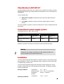
1
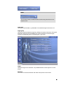
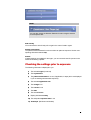
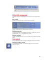
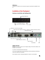
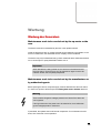
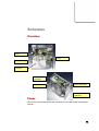
You have opted for a
high-frequency X-ray generator of the 8x Series –
thank you for your trust in our company.
Your STADLER ELEKTRONIK AG
1
EC Declaration of Conformity
PURSUANT TO
DIRECTIVE 93/42/EEC OF THE COUNCIL
DATED 14 JUNE 1993
IN RELATION TO M EDICAL DEVICES
Manufacturer, address:
Stadler Elektronik AG, Bahnhofstrasse 16
6014 Littau, Switzerland
Product:
High-Frequency X-RAY Generator
Type, article No.:
8x Series:
X-Ray Generator SE80X0, 275.000
Touch-Screen Operating Console (Elo-1529) 275.012
We hereby declare at our own responsibility that the products comply with the essential requirements pursuant
to Annex I of the aforesaid EC Directive, allowing for the Standards listed below.
IEC/EN 60601-1:1990 + A1:1993 +A2:1995, IEC/EN 60601-1-1 :2001, IEC/EN 60601-2-27 :1998
EMC Directive pursuant to IEC 601-1-2 :2001 : CISPR 11 :2002, IEC/EN 55011 :2002,
IEC/EN 61000-4-2 :2000, IEC/EN 61000-4-3 :2001, IEC/EN 61000-4-4 :2001,
IEC/EN 61000-4-5 :2001, IEC/EN 61000-4-6 :1996, IEC/EN 61000-4-8 :2000, IEC/EN 61000-4-11 :2001
CH-6014 Littau, 2006-05-26
Carlo Stadler
2
HIGH-FREQUENCY-X-RAY GENERATORS OF THE 8X SERIES
User Manual
distributed by:
manufactured by:
Stadler Elektronik AG
Bahnhofstrasse 16 • 6014 Littau • Switzerland
Phone +41 (0)41 250 56 33 • Fax +41 (0)41 250 56 77
www.stadler-elektronik.com • [email protected]
Document No. 976825 • Version 1 • Issue Date 2006-5-24
This document and the information contained herein are the property of Stadler Elektronik AG.
3
Contents
Technical safety information
5
CHAPTER 1
9
CHAPTER 2
14
Exposure mode
Patient management and X-ray journal
9
14
CHAPTER 3
17
CHAPTER 4
18
X-Ray Wizard
Settings
17
18
4
Technical safety information
Important information
SE80X0 high-voltage generators of the 8x Series are manufactured in compliance with
Directive 93/42/EEC of the Council dated 14 June 1993 in Relation to Medical Devices.
Since the product in question is not a sterile or implantable product, the corresponding
Points 7.5.2.ff of EN13485 are not applicable.
The high-voltage generator is but one component of a complete X-ray system. Accessories such as X-ray tube, high-voltage cables and collimator etc., are not covered by this
User Manual.
Use of this product as intended prerequires a knowledge of the User Manual on the part
of operating personnel. The operating personnel must have studied and understood the
User Manual before operating the system for the first time.
This equipment may be operated only by personnel availing of the required qualifications
for using an X-ray facility on patients and who have been trained in operating the unit.
The owner is responsible for compliance with the regulations applicable to the operation
of the X-ray facility.
The generator and its accessories may be transported only in the complete original
packaging.
The unit may be opened and serviced only by instructed personnel authorised by the
manufacturer.
Before using the X-ray facility, the user must ensure that all technical safety devices are
operable.
Warning
Ionising radiation (X-ray radiation) has a harmful effect on the human organism. Consequently, the legal provisions, such as legislation on shielding and dose monitoring, must be complied with.
5
Regulations
It is the task of the owner to comply with legal provisions relating to operation of X-ray
facilities. In particular, the applicable safety and radiation protection regulations must be
strictly followed.
Checks of the operational safety and operability of the unit must be conducted at regular
intervals. Please contact our After-Sales Servicing Department for this purpose.
We recommend that you demand a written confirmation (specifying the nature and
scope of the work and, possibly, information on any changes to rated data or working
area, date, name of the company and signature) in the case of all work performed on the
unit.
In the event of national provisions prescribing a shorter inspection interval, this shorter
inspection interval must be followed.
Modifications and add-ons to the unit must comply with the legal provisions and must
comply with the generally recognised rules of the art.
The manufacturer can be held responsible for safety, reliability and serviceability of the
unit only if the following instructions are complied with:
•
Installation, extension work, readjustment work, modifications or repairs
may only be performed only by the manufacturer himself or by personnel
authorised by him and failed components must be replaced by original
parts.
•
The electrical wiring must comply with the requirements.
•
The unit must be used in strict compliance with the User Manual.
Before using the X-ray facility, the user must ensure that all technical safety devices are
operable.
In the event of the unit being extended or modified by the owner with other equipment,
components or subassemblies and if this modification is not expressly indicated in the
technical documentation, the manufacturer or bodies authorised by him must be contacted in order ensure that safety of patients and operating personnel remains guaranteed.
Electrical safety
The unit may be opened only by authorised maintenance personnel. The unit may be
operated only in medical rooms and areas complying with the requirements of the Medical Device Directive 93/42/EEC and national installation standards.
The unit is designed only for non-detachable connection with all-pole disconnection from
the mains. This master switch must be designed in accordance with IEC60601. The
master switch must be clearly identified with 0/I.
The unit is not suitable for use in flammable mixtures of air with solvents, disinfectants
and anaesthetics or in flammable mixtures of anaesthetics and oxygen or laughing gas.
6
Classification to IEC 601-2-7
The high-voltage generator is but one component of a complete X-ray system. Accessories such as X-ray tube, high-voltage cables and collimators etc. are not covered by this
User Manual.
The unit complies with:
•
Safety class I, Type B, as regards the type of protection against electrical
shock and
•
Class IP20 as regards the degree of protection against ingress of water or
particles.
The unit is suitable for operation connected constantly to the mains in Standby state with
brief loading.
Connection to power supply system
Three-phase mains 3 x 400 V, 3 N AC, 50 Hz,
se8040
se8050
se8060
Fused with
3 x 40 A slowblow
3 x 40 A slowblow
3 x 40 A slowblow
Maximum mains internal
resistance
0.3 Ohm
0.2 Ohm
0.1 Ohm
Suitable for operation constantly connected to the mains with brief load peaks.
Warning
Dangerous, high voltages are applied to the high-voltage terminals. Dangerous voltages may be present inside the unit.
Installation
The unit must be assembled and installed in accordance with the country-specific installation regulations in order to ensure adequate cooling. In particular, the air must be able
to circulate freely around the unit.
The unit must be transported upright and protected to prevent it tipping over. During
transport, the generator may not be exposed to direct sunlight. The storage conditions
must be complied with.
Storage conditions:
Temperature:
0 °C ... +60 °C
Relative humidity: 10 % ... 90 %, no condensation
Atmospheric
700 hPa ... 1060 hPa
pressure:
Operating conditions:
Temperature:
+10 °C ... +40 °C
7
Relative humidity: 30 % ... 75 %
Atmospheric
700 hPa ... 1060 hPa
pressure:
Important information
No high voltage may be generated with the unit for a period of 24 hours
after transport!
Disposal
The unit contains electronic components, various plastics, oil and heavy metals. Consequently, after the generator has reached the end of its service life, it may not be simply
thrown away but must be disposed of correctly. Please contact our After-Sales Servicing
Department for this purpose.
Other information
Possible electromagnetic interference
Electromagnetic interference cannot be fully avoided owing to the high power demand.
Even though the units comply with the corresponding Standards, you are advised not to
install other sensitive equipment or devices near to the high-voltage generator. Moreover, you are advised to install the high-voltage generator adequately far away from
other equipment and devices that, in turn, may produce stronger interference fields, such
as MRI units.
Accessories and extensions
Please refer to the technical documentation for information on recommended accessories.
Only manufacturer-approved products may be used for add-ons (see technical documentation).
Pictorial symbols
The pictorial symbols on the operating panel are explained in the User Manual.
Other symbols:
Caution hazardous voltage
PE wire terminal
System earthing connection (green-yellow)
8
Chapter
1
Switching the unit on and off
Important information
The unit may be operated only if it is fully wired and installed and if the
housing has been fitted and screwed in place.
The system switch must have been switched on beforehand. The generator is then in
Standby mode.
Switch the unit with the On button. Switch the generator off and set to Standby mode
with the Off button.
Selecting the exposure parameters
Selection of user
The first time the software is launched, it prompts you to select the user:
Choose the corresponding user. This feature allows the software to be used for a practice with more than one accounting unit.
Note:
You can also choose the User Selection function using the shortcut on the
Exposure GUI.
MRA entry
In addition to the user, the MRA (Medical Radiology Assistant) can be specified for each
exposure. The entry may also be made later when assessing the exposure.
9
Note:
You can also choose the MRA Selection function using the shortcut on the
Exposure GUI.
Table type
Choose the required table, e.g. adult table. The anatomical regions are shown on it.
Organ group
Choose the required anatomical region by clicking on the figure of the body. The organs
assigned to this group are now displayed. In order to choose an anatomical region,
touch the corresponding point on the body figure, e.g. the arm.
Organ
Choose the organ to be examined. The possible directions for this organ are now displayed.
Direction
You must now choose the direction with which the exposure is to be made.
10
Note:
You can also choose the Direction Selection function using the shortcut
on the Exposure GUI.
Side of body
You must enter the side of body of the organ in the case of certain organs.
Patient assessment
The patient must be assessed in order to achieve an optimum exposure. Set the corresponding thickness in cm or step.
Plaster
If plaster settings are available for the organ, you can now set these if the person to be
examined is wearing a plaster.
Checking the settings prior to exposure
The following information is displayed to you:
1) The selected organ (or manual)
2) The ray direction
3) The patient assessment in cm and, if applicable, in steps (this is not displayed
if you are working with automatic exposure).
4) The selected application unit
5) The voltage in kV
6) The current in mA
7) The mAs
8) The selected focus
9) Display with/without bucky
10) The anticipated exposure time in ms
11) Technique (film/sheet combination)
11
12) Density from 0 (very light) to 15 (very dark)
4)
1) 2)
5)
6)
7)
3)
11)
3)
12)
10)
8) 9)
Important information
You must check the set values on the display before triggering the exposure.
Data transfer to the generator
You can press the Transfer button after making the settings. The generator now receives the settings and can perform the exposure.
Exposure
Preparatory phase
Preparation is activated by switching (1st stage, Figure 2) the manual trigger.
Trigger phase
After you see message "Ready for exposure" you can make the exposure by fully
depressing the manual trigger (2nd stage, Figure 3).
After exposure
After exposure, the operator is prompted to judge the image quality of the radiograph just
made. Now click on "Next patient" or "Next exposure" to continue.
12
Exiting the program
You can exit the program with the Tab-5 button. Depending on setting in Options, you
are prompted to back up the data. The Save X-Ray Journal dialog box is displayed for
this purpose.
13
Chapter
2
Patient management
and X-ray journal
Note
Incorrect entries in Patient Management may lead to confusion and/or repeated exposures.
Selecting the patient
The patient data can be selected by clicking on the Tab-2 button. You will then see a
window in which you can select the required patient.
Patient search
You can search for the patient in the Patient Data window by entering the first few letters
of the name or first name in the corresponding fields.
You can also skip to the start or end of the data with the Navigator.
If an interface to an external practice system is set up, the patient data is imported directly to this practice system. In this case, you will not see the Patient Selection window.
Selecting the patient
Click at the left on a button in the filtered patient list. The selected patient is now active.
You can now change or delete the data record.
Note:
14
You can also select Patient Selection using the shortcut on the Exposure
GUI.
Patient data management
You can also manage the patient data in the same window you use to select the patient
data.
New patient
First click on the New patient button to enter the data of a new patient.
Save the new data with "Save" or discard the data with "Discard".
Editing patient data
You can change the data of an existing patient by clicking on the "Edit" button. Save the
changed data with "Save" or discard the data with "Discard".
Deleting a patient
The data of an existing patient can be deleted irretrievably from the database with Delete
patient.
X-ray journal
A journal of all exposures made is managed constantly when working with the software.
Displaying the X-ray journal
Choose a patient and then click on the Tab-2 button again. You will see the patientspecific X-ray journal:
15
Important information:
If you choose the "Delete filter" button, the X-ray journal will no longer be
displayed patient-specifically but chronologically.
16
Chapter
3
X-Ray Wizard
You can retrieve explanatory images, texts and videos further to the settings just selected with the Information button (Tab-3 button).
Note
Incorrectly assigned X-Ray Wizard data may lead to incorrect exposures
and repeated incorrect exposures.
17
Chapter
4
Settings
Click on the Tab-4 button to allow you to make various settings:
Organ Table Editor
New organ tables can be created and existing tables can be changed or deleted with the
Organ Table Editor. These settings are made by your authorised servicing company
when commissioning the system.
Note
Changes to the predefined organ programs may impair image quality and
increase radiation exposure.
Remote maintenance
If you have registered this option, click on this button when instructed to do so by your
authorised servicing partner to activate remote maintenance and ensure access to your
unit.
Important information
All data, including sensitive patient data, can be seen by the servicing
technician as soon as you enable remote maintenance access.
18
HIGH-FREQUENCY X-RAY 8X GENERATORS
Technical Documentation
distributed by:
manufactured by:
Stadler Elektronik AG
Bahnhofstrasse 16 • 6014 Littau • Switzerland
Telefon +41 (0)41 250 56 33 • Fax +41 (0)41 250 56 77
www.stadler-elektronik.com • [email protected]
Document No. XXX.YYY • Revision 0 • Issue Date 2006-05-24
This document and the information contained herein are the property of Stadler Elektronik AG.
1
Contents
Notes on safety
Important
Regulations
Electrical Safety
Classification according to IEC 601-2-7
Connection to mains electrical supply
Installation
Disposal
Further information
Possibility of electromagnetic interference
Accessories and extensions
Symbols
Installation instructions
Installation of the generator
In-house wiring
Fuse protection
Installation
Residual-current circuit breaker
Connection to the mains supply
Connection of external components
Final tasks
Initial use
Installation of the Touchpanel
Hardware installation and Configuration
Admin Console
Wartung
Wartung des Generators
Maintenance interval
Maintenance of the Touchpanel
Calibration
Change of Harddisk
Cooler
Connection to peripheral devices
High-voltage cable
X-ray tube
Moving grid
Measuring chambers
4
4
4
5
5
6
6
7
7
7
7
7
8
8
8
8
8
8
8
9
9
10
10
10
10
12
12
13
13
13
13
13
14
14
14
15
15
2
Stand
Foot-switch
Options
GDT Interface
Skribordrucker
DAP
Stand
Foot-switch
Options
Schemas
Overview
Fuses
15
15
15
16
16
16
16
16
17
18
18
18
3
Notes on safety
Important
8x series high-voltage generators are manufactured in accordance with the EU's medical
device directive 93/42/EEC of the 14th of June 1993.
A high-voltage generator is merely a component part of a complete x-ray machine installation. Accessories such as the x-ray tube, high-voltage cable, collimator etc. will not be
covered by this technical documentation.
Usage of this product in accordance with regulations assumes a knowledge of its operating instructions on the part of its users. These must be studied and understood before
initial use.
This device may only be operated by staff with the necessary qualifications for using an
x-ray installation on patients and who have been instructed in its operation.
The operator will be held responsible for keeping to the regulations applicable for the
usage of an x-ray installation.
No responsibility for parameters changed by the user to the APR, to the XRAY Wizard or
other functions is taken by the manufacturer.
The device may only be opened and maintained by trained staff and with the manufacturer's authority.
Warning
Ionizing radiation (x-ray radiation) can endanger the health of patients and
operating staff alike. For this reason, statutory regulations concerning
shielding and exposure monitoring must be observed.
Regulations
It is the operator's responsibility to observe the statutory regulations regarding the operation of x-ray installations. In particular, the applicable safety and protection from radiation
regulations are to be heeded to the letter.
In accordance with maintenance instructions, checking of operating safety and functionality of the device is to be carried out at regular intervals of 12 months. To achieve this,
please contact our authorized service agent.
If national regulations lay down a shorter service interval, then this is to be followed.
4
Alterations and additions to the device must comply with statutory regulations and the
generally accepted technological standards.
The manufacturer will only be regarded as responsible for the device's safety, reliability
and serviceability if the following are observed:
•
Assembly, add-ons, readjustments, alterations or repairs may only be undertaken by the manufacturer himself or by staff acting under his authority.
Any defective components are to be replaced by original spare parts.
•
Electrical installation must correspond to the demands placed upon it.
•
The device must only be used if in accordance with its instruction manual.
We recommend that you request written confirmation of all work carried out on the device (type and extent of work, if need be giving details of changes to its characteristics or
to its operating environment, plus the date, company's name and a signature).
Before using an x-ray installation, the user must satisfy himself that all safetyengineering devices are functioning.
If the device is to be extended or altered by its operator, using other devices, components or modules, and if this modification is not clear and obvious from the technical
documentation, then the manufacturer or bodies authorized by him must be contacted to
ensure that the safety of patients or users is not compromised.
Electrical Safety
Important
The device may only be opened by authorized maintenance staff.
The device may only be operated in clinical areas that satisfy the demands of the EU's
medical products directive 93/42/EU.
The device is only intended for fixed connection using an all-pole mains cut-out. This
main switch must be installed in accordance with IEC60601. The main switch must be
marked with 0/I.
The device is not suitable for use in inflammable mixtures of solvent, disinfectant or anaesthetic substances with air, or in inflammable mixtures of anaesthetic substances and
oxygen or laughing gas.
Classification according to IEC 601-2-7
Our high-voltage generator is only one component of a complete x-ray installation. Accessories, such as x-ray tubes, high-voltage cables, collimators etc. will not be covered
by this technical documentation.
The device complies:
•
According to its type of protection from electric shock,
with Protection class I, Type B
5
•
According to its degree of protection against penetration by water
or particles in Class IP20
The device is suitable for continuous short-duration loading when connected to the
mains and in standby mode.
Connection to mains electrical supply
Three phase mains supply 3 x 400V, 3N~, 50Hz,
Fuse protection
SE8040
SE8050
SE8060
3 x 40 A slow
3 x 40A slow
3 x 40 A slow
0.2 Ohm
0.1 Ohm
Maximum mains
0.3 Ohm
supply internal resistance
Suitable for continuous mains operation with short-term peak loading
Warning
Dangerously high voltages occur at the high-voltage connections. Dangerous voltages can be present inside the device.
Installation
In order to guarantee adequate cooling, the device must be assembled and installed in
accordance with the installation instructions. In particular, air must be able to circulate
freely around the device.
The device must be transported upright and safeguarded against tipping over. During
transportation, the generator may not be exposed to direct sunlight. Storage conditions
have to be met.
Storage conditions:
Temperature:
Humidity:
Pressure:
0°C ... +60°C
10% ... 90% no condensation
700hPa ... 1060hPa
Operating conditions:
Temperature:
Humidity:
Pressure:
+10°C ... +40°C
30% ... 75%
700hPa ... 1060hPa
Important
After transport, high voltage may not be generated using the device for a
period of 24 hours!
6
Disposal
This device contains electronic components, various plastics, oil and heavy metals. At
the end of its useful life, the generator may not be just thrown away but must be disposed of in a professional manner. Please contact the authorised service agent for assistance in this connection.
Further information
Possibility of electromagnetic interference
Due to the device's high power requirement, electromagnetic interference cannot be
entirely avoided. Although our devices correspond to the applicable norms, it is recommended that no other sensitive equipment be set up in the vicinity of the high-voltage
generator. Furthermore it is recommended that high-voltage generators be located at a
sufficient distance from other equipment, such as MR devices, since these in turn can
generate large-scale noise fields.
Accessories and extensions
You can find details of recommended accessories in the 'Connection to peripheral devices' chapter of this technical documentation.
Only products that have been cleared by the manufacturer may be used for extension
purposes.
Symbols
The symbols on the operating console are explained in the operating instructions.
Other symbols:
Danger: High voltage
Earthing connection
System earth connection (green- yellow)
Equipotential bonding
7
Installation instructions
Installation of the generator
In-house wiring
5-pole mains cable 3PNE, enclosed, is to be used.
•
Cross-section for each core: at least 10mm2
•
Max. length: Any length, provided that the nominal resistance at the de-
vice is sufficiently low (see table under 'Connection to mains supply')
Important
Braided conductors may not be tinned, since they will be attached using
terminals.
Fuse protection
The identifiers for the in-house fuses are to be noted on the device, so that the applicable fuses can be quickly found when needed.
The ratings for the fuses can be obtained from the table in the 'Connection to mains
supply' section.
Installation
The device is to be placed with its rear panel against a wall and with a clearance of at
least 5 cm.
Cables connected must be fixed in such a manner that by pulling on them it will be impossible for the device to tip over.
Residual-current circuit breaker
The Raymat AS1 System must have a Residual-current circuit breaker.
Connection to the mains supply
The earth cable must be connected to the point marked with the symbol (<<).
A green signal lamp must be fitted in the power supply cable to indicate that the device is
being supplied with power.
8
A main switch must be installed in order to block power to the device. This main switch
must be able to permit an all-pole mains cut-out and provide a breaking capacity to at
least the level of the fuse protection.
Connection of external components
All cables connected to the device must be protected from tension. The installation must
comply with country-specific norms.
High-voltage cable
Only high-voltage cables with the following properties may be taken into use:
•
Consisting of 3 individual cores
•
Operating voltage at least 75kV
•
Testing voltage for screening at least 120kV=
Inner conductor one against the other 5kV=, 1kV~
•
Working temperature 0 – 60°C
•
Length max. 25m
•
Resistance of screening < 10mOhm / m
•
Capacity of all inner conductors against the screening < 160pF / m
The plugs for the high-voltage cables must be greased with silicon when connecting the
x-ray tube to the generator or when replacing the tube. Furthermore, the plugs must be
secured using grub screws in such a way that tools are required for removing the cables.
The tube must be connected to the generator's earth using a yellow/green cable with a
cross-section of at least 10mm2 and to a terminal marked with the symbol (<<).
Moving grid
Please agree this with the manufacturer.
Measuring chambers
Please agree this with the manufacturer. For Comet measuring chambers, the chamber's housing must be fitted using insulation.
Operating console
The operating console must be so arranged that the user can view its display when making the exposure.
If the external operating console is used together with the PC option, check the cabling
against the VDE0107 norm and in particular for its trouble-free operation.
Miscellaneous
For connecting a visual warning (flashing or warning light) that shows dangerous initial
values are present, please agree this with the manufacturer first.
Connection for door contact: Installation must conform to the VDE0107 norm.
Check it is working correctly.
Final tasks
The cover must be attached to the chassis using all 4 screws.
9
Initial use
Preparation for initial use is to be carried out using the manufacturer's installation checklist.
Installation of the Touchpanel
Hardware installation and Configuration
Display Brightness
On- / Off (push 3 Sec. to
shut down the touchpanel)
Volume
Bus bar for 12V DC Power Supply
4 USB-Connection (Mouse, Keyboard, USB-Stick, Harddisk, DVD-Rom, Skribor)
Netzwerkanschluss
COM1 Port (PC-Interface)
COM2 Port (DAP or Skribor)
PS/2 Keyboard
PS/2 Mouse
Admin Console
General: In the Admin Console you can configure settings Touchscreen, Network, Time
and Date or set Passwords.
To get to the console please follow these steps:
Turn on the Touchpanel with connected keyboard. Press the shift-button while booting
until you are asked to enter password.
Enter Username “admin” and Password (default = “8xaccess”, see Checklist)
10
11
Wartung
Wartung des Generators
Maintenance work to be carried out by the op-erator or the
user
The device must not be maintained by the user or the operator himself.
Inside the device there are no components that can be repaired by the operator. In the
event of a malfunction, the authorized service company is to be contacted.
The device may only be disinfected using a cloth moistened with a disinfectant solution.
On no account pour or spray disinfectant solution over it.
Important
When disinfection is being carried out, the device is to be switched off at
the main switch. The device may only be switched on again once the disinfectant solution has completely evaporated.
Maintenance work to be carried out by the manufacturer or
by authorized agents
Before opening the device, the power supply must be switched off at the main switch
(i.e. there is no power to the device) and a waiting time of two minutes observed.
Warning
There could be dangerous voltages present in the device if the above advice is ignored.
If during maintenance the power has to be switched on, there will be dangerous voltages present in the device.
If prescribed, then please service all internal components. If no maintenance is laid
down, then check their correct operation.
12
Maintenance interval
Maintenance must be undertaken in accordance with statutory guidelines (quality assurance). If no stricter checks are laid down by law, then the high-voltage generator must be
serviced at least every 12 months in accordance with the manufacturer's regulations.
This maintenance consists of a simplified zeroing in of the installation, during which the
initial settings for voltage, power and power-time product are checked.
In addition, every 10 years the transformer's oil is be analysed and its level checked at
the same time.
Maintenance of the Touchpanel
Calibration
Please contact your service company for correct calibration based on manufacturer
suggestion.
Change of Harddisk
Please contact your service company for correct harddisk change based on manufacturer suggestion (3 years interval recommended).
Cooler
The cooler should be cleaned from dust while maintenance.
13
Connection to peripheral devices
High-voltage cable
High-voltage generators of the 8x series can be safely operated with the following components:
(As at July 2004)
Manufacturer:
Cable type
Comet
Type 'K' HV cable
Comet
Type 'CF' HV cable
Claymount
HV cable
Important
The plugs for the high-voltage cables must be greased with silicon when
connecting the x-ray tube to the generator or when replacing the tubes.
X-ray tube
The list of tubes that can be used with the 8x series high-voltage generators is subject to
constant revision. The manufacturer will provide information regarding suitability on request.
It is the intention to connect the pressure control switch to the x-ray tube.
Important
Every device is configured at the factory to accept a given number of tubes. The data required for this is stored within the generator. Under no circumstances may you connect other tubes than those for the applicable
software version.
When replacing a tube, the plugs for the high voltage cables must be re-greased using
silicon.
14
Moving grid
Moving grids from the following manufacturers can be fitted:
•
Kehrli
•
Eurostrazza
•
Yamato
•
Liebel-Flarsheim:
Par Speed 230V/115V
•
Liebel-Flarsheim:
Super Speed 230V/115V
•
MTK
•
MTS, Buckywand 92
•
Fixed grid
For the above-named moving grids, connection diagrams can be obtained from Stadler
Elektronik.
Moving grids can be switched on via the 'make ready' signal, during the preparation and
exposure phase.
Measuring chambers
Measuring chambers from these manufacturers:
•
Comet
(The housing for the Comet measuring chamber must be fitted using insulation)
Instructions for adapting to the high-voltage generator can be obtained from the manufacturer.
Stand
The stand does not detract from the high-voltage generator's safety, provided no electrical connection exists between the latter and the stand.
Foot-switch
Foot-switches for medical purposes can be obtained from Steute Schaltgeräte GmbH &
Co.
Options
Further additional appliances can be connected to the generator. Their functions and
installation notes are described on special instruction sheets. These can be requested
from Stadler Elektronik AG.
Additional options:
15
•
PC interface with external 'ON' switch box
•
Extension for the hand release
•
Interface for automatic exposure
•
Adjustment of the performance level
•
Fast warm up rotary collector
•
Preparation and release display
If a component is to be used that is not carried in the above list, or which does not correspond to the specifications in the above list, then the manufacturer will have to be
contacted.
GDT Interface
8x series generators can perform GDT-Interfacing with a practise software.
Version 2.0 issue (5/98), 4.3.1999 and Version 2.1 issue (5/2001). Software companies
of practise administration software can download the
Stadler GDT-Protocol now. Please ask by phone for the access code.
Skribordrucker
Folgende Geräte können zur Ausgabe der Skriborinformationen verwendet werden:
•
HP LaserJet1020
•
Brother P-Touch 2420PC
•
Liechti Displaybelichter
DAP
8x series xray generators are compatible to the following DAP-Meter:
•
PTW Diamentor E2
Stand
The stand does not detract from the high-voltage generator's safety, provided no electrical connection exists between the latter and the stand.
Foot-switch
Foot-switches for medical purposes can be obtained from Steute Schaltgeräte GmbH &
Co.
16
Options
Further additional appliances can be connected to the generator. Their functions and
installation notes are described on special instruction sheets. These can be requested
from Stadler Elektronik AG.
Additional options:
•
PC interface with external 'ON' switch box
•
Extension for the hand release
•
Interface for automatic exposure
•
Adjustment of the performance level
•
Fast warm up rotary collector
•
Preparation and release display
If a component is to be used that is not carried in the above list, or which does not correspond to the specifications in the above list, then the manufacturer will have to be
contacted.
17
Schemas
Overview
HZU
DAU
HSU
HS-Trafo
AEC Interface
(optional)
CPU Board
Power Interface 1
Power Interface 2
(optional)
Fuses
Remove the circuit breaker window with a screwdriver in accordance with the illustration
carefully.
18
Behind the cover you see the following circuit breaker:
Main contactor
switches the entire generator
STBY
supply voltage CPU
Steuer
supply voltage control power
Ext
supply voltage periphery
•
19
20
21