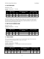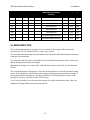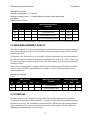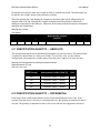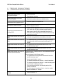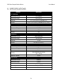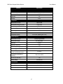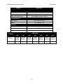
1
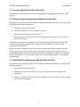
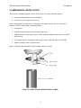
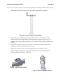
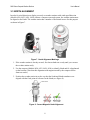
Model 9620 Series Compact Weather Stations User’s Manual Rev. A All Weather Inc. • 1165 National Drive • Sacramento, CA 95834 • USA • 800.824.5873 • www.allweatherinc.com Copyright © 2015, All Weather, Inc. All Rights Reserved. The information contained herein is proprietary and is provided solely for the purpose of allowing customers to operate and/or service All Weather, Inc. manufactured equipment and is not to be released, reproduced, or used for any other purpose without written permission of All Weather, Inc. Throughout this manual, trademarked names might be used. Rather than put a trademark (™) symbol in every occurrence of a trademarked name, we state herein that we are using the names only in an editorial fashion and to the benefit of the trademark owner, and with no intention of infringement. All Weather, Inc. and the All Weather, Inc. logo are trademarks of All Weather, Inc. Disclaimer The information and specifications described in this manual are subject to change without notice. Latest Manual Version For the latest version of this manual, see the User Manuals page under Support on our Web site at www.allweatherinc.com/. All Weather, Inc. 1165 National Drive Sacramento, CA 95834 Tel.: (916) 928-1000 Fax: (916) 928-1165 Contact Customer Service Phone support is available from 8:00am - 4:30pm PT, Monday through Friday. Call 916-9281000 and ask for “Service.” Online support is available by filling out a request at www.allweatherinc.com/support/onlinesupport/ E-mail your support request to [email protected] 9620 Series Compact Weather Stations User’s Manual Revision History Revision Date A 2015 June 25 Summary of Changes Initial release. 9620 Series Compact Weather Stations User’s Manual TABLE OF CONTENTS 1. OVERVIEW .........................................................................................................................1 1.1 Models ........................................................................................................................................ 1 1.2 Accessories ................................................................................................................................. 1 2. THEORY OF OPERATION .................................................................................................2 2.1 Air Temperature and Humidity .................................................................................................. 2 2.2 Air Pressure ................................................................................................................................ 3 2.3 Precipitation ................................................................................................................................ 3 2.4 Wind ........................................................................................................................................... 3 2.4.1 Compass .............................................................................................................................. 3 2.5 Global Radiation ......................................................................................................................... 3 3. INSTALLATION ...................................................................................................................4 3.1 Selecting the Installation Location ............................................................................................. 4 3.1.1 Wind Speed/Direction (Models 9620, 9623, 9624, 9626) .................................................. 4 3.1.2 Compass (Models 9620,9623, 9624, 9626) ........................................................................ 5 3.1.3 Radar Precipitation Measurement (Models 9622 and 9624) .............................................. 5 3.1.4 Global Radiation Measurement (Models 9625 and 9626) .................................................. 5 3.2 Mechanical Installation ............................................................................................................... 6 3.3 North Alignment ......................................................................................................................... 8 3.4 Default Configuration ................................................................................................................. 9 3.5 Electrical Connections ................................................................................................................ 9 3.5.1 Summary of Signal and Power Wiring Connections ........................................................ 10 4. OPERATION WITH AN AWOS ......................................................................................... 11 4.1 Sensor Reports .......................................................................................................................... 11 4.1.1 Topic-Based Sensor Poll Commands................................................................................ 11 4.1.2 Check Sum Calculation..................................................................................................... 13 5. STANDALONE MEASUEMENT OUTPUTS ...................................................................... 15 5.1 Measurements Generated.......................................................................................................... 15 5.1.1 Current Measurement (act) ............................................................................................... 15 5.1.2 Minimum and Maximum Values ...................................................................................... 15 5.1.3 Average Value .................................................................................................................. 15 5.1.4 Vectorial Average Value (vct) .......................................................................................... 15 5.2 Air and Dew point Temperature ............................................................................................... 16 5.3 Wind Chill Temperature ........................................................................................................... 16 5.4 Humidity ................................................................................................................................... 16 5.5 Air Pressure .............................................................................................................................. 17 5.6 Wet Bulb Temperature ............................................................................................................. 17 5.7 Wind Speed ............................................................................................................................... 17 5.8 Wind Direction ......................................................................................................................... 18 5.9 Wind Measurement Quality ...................................................................................................... 19 5.10 Compass .................................................................................................................................. 19 5.11 Precipitation Quantity — Absolute ........................................................................................ 20 9620 Series Compact Weather Stations User’s Manual 5.12 Precipitation Quantity — Differential .................................................................................... 20 5.13 Precipitation Intensity ............................................................................................................. 21 5.14 Precipitation Type ................................................................................................................... 21 5.15 Heating Temperatures ............................................................................................................. 22 5.16 Global Radiation ..................................................................................................................... 22 6. CONFIGURATION ............................................................................................................ 23 7. MAINTENANCE ................................................................................................................ 24 8. TROUBLESHOOTING ...................................................................................................... 25 9. SPECIFICATIONS ............................................................................................................ 26 10. WARRANTY .................................................................................................................... 29 9620 Series Compact Weather Stations User’s Manual 1. OVERVIEW The 9620 Series of Compact Weather Stations provides low-cost, light-weight weather stations that can collect a variety of meteorological data based on the specific data you need. The portable design of the 9620 Series makes this series of Compact Weather Stations ideal for a variety of unique applications while providing the same level of accuracy and dependability that you get with AWI’s existing modular sensors. The 9620 Series of Compact Weather Stations may be used on a standalone basis connected to your own data logging system, or may be connected to either All Weather Inc. Model 1191-I Data Collection Platform or Model 2715 Universal Power and Communication Module. Both All Weather Inc. units provide a power, communication, and data aggregation capability to allow the 9620 Series of Compact Weather Stations to be used an automated weather observation system. 1.1 MODELS The following models are available. Weather Parameter Model Temp/ Humidity Pressure Precipitation Wind Speed/ Direction Compass X X X X X X 9620 9621 X X 9622 X X 9623 X X 9624 X X 9625 X X 9626 X X Solar Radiation X X X X X X 1.2 ACCESSORIES The following accessories and replacement parts are available for the 9620 Series of Compact Weather Stations. Part Number M488628-00 Description Tower Crossarm Mounting Kit 1 9620 Series Compact Weather Stations User’s Manual 2. THEORY OF OPERATION Each weather parameter is measured using a technology that is suited to measuring that parameter, and has become well-established measuring that parameter in standalone systems. 9620 Series models that measure precipitation or wind speed/direction are heated for operation in freezing conditions. The measured values are sent over an RS-485 interface in accordance with UMB protocol. The Weather Station is polled once a second, and sends the weather data in response to the poll. Figure 1 shows the possible Compact Weather Station sensors. Figure 1. Possible Compact Weather Station Sensors Note that not all the sensors will be present on a given Compact Weather Station model. 2.1 AIR TEMPERATURE AND HUMIDITY Temperature is measured using a highly accurate NTC thermistor whose resistance varies with temperature. Relative humidity is measured using a capacitive humidity sensor. In order to keep the effects of external influences such as solar radiation as low as possible, these sensors are located in a motor-aspirated housing with radiation protection. In contrast to conventional nonventilated sensors, this allows significantly more accurate measurement during high-radiation conditions. The dew point is calculated from the air temperature and relative humidity readings. 2 9620 Series Compact Weather Stations User’s Manual 2.2 AIR PRESSURE The air pressure is measured using a built-in MEMS (microelectromechanical) capacitive sensor. The altimeter setting and relative air pressure referenced to sea level can be calculated using the known elevation of the sensor above mean sea level, which is user-configurable on the equipment. 2.3 PRECIPITATION Precipitation is measured by the R2S-UMB sensor, which uses radar technology to measure precipitation. The sensor works with a 24 GHz Doppler radar that measures the drop speed and calculates the precipitation quantity and type by correlating the drop size and speed. Note that this method of measuring precipitation has not been approved by aviation authorities in some countries. 2.4 WIND Wind speed and direction are derived using measurements from four ultrasonic transducers. The transducers are located at 90° intervals, and are oriented north/south and east/west. The transducers emit sound waves that are detected by the opposite transducers, and wind affects the travel times of the sound waves. This information can then be used to calculate the vector components of the wind speed and the wind direction relative to true north. 2.4.1 Compass The integrated electronic compass is used to check the north/south adjustment of the sensor housing for wind direction measurements. It is also used to calculate the compass-corrected wind direction (wind direction relative to magnetic north). 2.5 GLOBAL RADIATION Global radiation is measured by a pyranometer mounted in the top cover of the Compact Weather Station. 3 9620 Series Compact Weather Stations User’s Manual 3. INSTALLATION 3.1 SELECTING THE INSTALLATION LOCATION Pay attention to the following points when selecting the installation location. Stable subsurface for installing the mast foundation Reliable power supply The mast and the sensor must be grounded in accordance with regulations The following sections provide siting guidelines for each sensor model. SUGGESTION: Take a picture at the installation site in each direction (north, east, south, and west) to record the topography and obstructions for future reference. 3.1.1 Wind Speed/Direction (Models 9620, 9623, 9624, 9626) Buildings, bridges, and trees may corrupt the wind measurement. Equally, passing traffic may cause gusts that may influence the wind measurement. The standard exposure of wind instruments over level open terrain is 10 m above the ground. Open terrain is defined as an area where the distance between the sensor and any obstruction is at least 10 times the height of the obstruction. Figure 2 shows the minimum siting considerations (height above ground, distance from obstructions and roads) for a weather station monitoring wind speed/direction. Figure 2. Minimum Siting Considerations for Wind Speed/Direction 4 9620 Series Compact Weather Stations User’s Manual 3.1.2 Compass (Models 9620,9623, 9624, 9626) An aluminum or other nonferrous mast is recommended for mounting a weather station with a compass. 3.1.3 Radar Precipitation Measurement (Models 9622 and 9624) Pay attention to the following points when selecting the installation location for a weather station with radar precipitation measurement. Installation at the top of the mast Installation height at least 4.5 m above the ground Distance to road carriageway at least 10 m Distance from moving objects (e.g., trees, bushes and even bridges) at least 10 m at the height of the sensor Falling or moving objects, even falling leaves or leaves blowing in the wind, may cause false measurements and/or precipitation types. Strong winds can influence the accuracy of the precipitation measurements. When selecting the installation location, take care to position the weather station at a suitable distance from other systems incorporating 24 GHz radar, such as traffic counting devices on overhead gantry signs. Otherwise cross effects and system malfunctions may occur. In the final analysis, the distance to other measuring systems also depends on their range of coverage and signal strength. 3.1.4 Global Radiation Measurement (Models 9625 and 9626) Pay attention to the following points when selecting the installation location for a weather station with a pyranometer. Installation at the top of the mast Shadow-free location, if possible 360° free view to the horizon at the height of the pyranometer Distance to shadow-casting objects (trees, buildings) at least 10 times of the object height relative to the pyranometer 5 9620 Series Compact Weather Stations User’s Manual 3.2 MECHANICAL INSTALLATION There are two installation options for the 9620 Series of Compact Weather Stations. U-bolt mounting bracket to mast (included) Crossarm to tower (optional accessory) For the mast option, the sensor base is designed to be installed on the top of a mast with a diameter of 60 to 76 mm using a mounting bracket. 1. Loosen nuts. 2. Push the sensor from above onto the top of the mast. 3. Tighten the nuts evenly until contact is made with the springs but the sensor can still be moved easily. 4. For weather stations measuring wind speed/direction, align the sensor to the North. 5. Tighten both nuts with 3 complete turns. Figure 3 illustrates the installation of the weather station on a mast. Figure 3. Install Compact Weather Station on Mast 6 9620 Series Compact Weather Stations User’s Manual For the tower crossarm option, the sensor base is attached to a mounting bracket on the crossarm. 1. Position the crossarm next to the tower where the crossarm will be mounted. Figure 4. Position Crossarm for Mounting 2. Each of the two mounting braces has independent mounts so that the brace can be attached to the tower independently of positioning the crossarms in the braces. Use a carpenter’s level to keep the crossarm as level as possible while securing each brace to a tower leg. 3. Position the crossarm in the brace so that the area where the weather station will be mounted is at the desired distance from the tower. 4. Position the weather station on the mounting plate at the end of the crossarm. 5. Tighten all the mounting nuts, except for weather stations measuring wind speed/ direction (Models 9620, 9623, 9624, 9626). Figure 5. Mounting Brace Detail Figure 6. Mount the Weather Station 7 9620 Series Compact Weather Stations User’s Manual 3.3 NORTH ALIGNMENT In order for wind direction to display correctly on weather stations with wind speed/direction (Models 9620, 9623, 9624, 9626) without a compass-corrected system, the weather station must be aligned to the North. The weather station has a number of directional arrows for this purpose as shown in Figure 7. Figure 7. North Alignment Markings 1. If the weather station is already secured, first loosen both nuts evenly until you can turn the weather station easily. 2. Use the compass (Models 9620, 9623, 9624, 9626) to identify North and fix a benchmark on the horizon. (Note that this alignment with magnetic north by the compass differs from true north.) 3. Position the weather station in such a way that the South and North transducers are aligned with the fixed point of reference in the North (see Figure 8). Figure 8. Correct Magnetic North Alignment 8 9620 Series Compact Weather Stations User’s Manual 3.4 DEFAULT CONFIGURATION Table 1. Default Configuration Baud Rate 19200 bps RS-485 Binary Calculation Interval 10 measurements 0m Elevation Above MSL 3.5 ELECTRICAL CONNECTIONS There is an 8-pole screw connector on the bottom side of the weather station as shown in Figure 9. This serves to provide the supply voltage and serial interface by way of the supplied connection cable. Figure 9. Sensor Electrical Connections Pin Color Function 1 White Power Supply GND 2 Brown Power Supply + 3 Green RS-485 (D+) 4 Yellow RS-485 (D–) 7 Blue Heater GND 8 Red Heater + 9 9620 Series Compact Weather Stations User’s Manual 3.5.1 Summary of Signal and Power Wiring Connections Table 2 provides the serial connections for the default half-duplex RS-485 serial communication option. The Model 2715 Universal Power and Communication Module may also be configured to provide RS-232 or full-duplex RS-485 signals at Serial Output 1. The Model 2715 Universal Power and Communication Module User’s Manual describes these wiring options and explains how to install the required firmware to support these options. Table 2. Model 9620 Series Compact Weather Station Signal and Power Wiring Serial Output 2 Pin Function Color 1 + 24 V DC BROWN RED 2 PGND WHITE BLUE 3 RS-485 (D–) YELLOW 4 RS-485 (D+) GREEN Serial Output 1 Pin Function 3 RS485 (D–) 4 RS485 (D+) 5 GROUND Color Any colors may be used as long as they match the signals on each end of the connection. DC Power Pin Function Color 5 Battery + RED 6 Battery – BLACK AC Pin Function Color 1 HOT BLACK 2 NEUTRAL WHITE 3 GROUND GREEN 10 9620 Series Compact Weather Stations User’s Manual 4. OPERATION WITH AN AWOS 4.1 SENSOR REPORTS The 9620 Series of Compact Weather Stations is a polled sensor and the sensor responds when it is polled by the computer. The Model 2715 Universal Power and Communication Module (UPCM) supplies power to the weather station and provides a communication interface with the data processing computer. The communication interface can be either serial or TCP/IP. Data transfer across the serial interface between the UPCM and the computer is implemented by default via a serial, ASCII encoded, half duplex, 4800 bps, 8-N-1. This allows for the data to go on the data bus for the Data Collection Platform. 4.1.1 Topic-Based Sensor Poll Commands These Topic-based poll commands from the data processing computer are used to poll sensors connected to the UPCM. A Topic-based poll command has the following format. PWRaaTOPIC 110|120|130|150|…|1174,<CRC><CR><LF> where aa is the address of the sensor or the sensor location. This address is often 00. The topics being polled are then listed based on the specific weather station model connected to the UPCM, and the specific topics that are to be polled. Note that there is a pipe between each topic that is being polled. See the notes below Table 8 for more information about Topic 1301. The response to the poll will be a string formatted according to the response formats specified for the topics. =PWRaaTOPIC 110=xxx.xx|120=xxx|130=xxx.xx|150=xx|… |1174= xxx.xx<EOF><CRC><CR><LF> where EOF is the end of file marker. The CRC is a 4-character CRC that is calculated as explained later in this chapter. The specific topics are explained in the tables below. Table 3. Ultrasonic Wind Sensor Poll Topics (Models 9620, 9623, 9624, 9626) 110 120 Instant wind speed Instant wind direction 11 xxx.xx xxx 9620 Series Compact Weather Stations User’s Manual Table 4. Temperature/Relative Humidity Poll Topics (Models 9621, 9622, 9623, 9624, 9625, 9626) 210 220 Instant temperature (°C) Instant relative humidity xxx.xx xxx 230 250 Instant dew point (°C) Alarm byte xxx.xx x Table 5. Barometric Pressure Sensor Poll Topics (Models 9621, 9622, 9623, 9624, 9625, 9626) 312 Pressure (in Hg) xxx.xx Table 6. Precipitation Poll Topics (Models 9622, 9624) 612 Precipitation ID xx 621 Accumulation (mm/h) Table 7. Analog Topics (Models 9625, 9626) 1174 2 Solar radiation (W/m ) Table 8. Ancillary Topics 1385 Model 9620 Series Status Word xx 12 xxx.xx xx.xx 9620 Series Compact Weather Stations User’s Manual 4.1.2 Check Sum Calculation The CRC is calculated using a standard crc-16 formula. The algorithm is as follows. /* CRC routine used with AWOS remote sensors USE: crc = crc16(buffer, length, initial_value) where: crc is the returned value, buffer is the data buffer to compute a crc length is the number of bytes in buffer to process initial_value is the results of previous crc calculations that will allow the buffer crc to be computed in stages if necessary. If this is not necessary, then set initial_value to 0. */ unsigned int crc16(char *string, unsigned int length, unsigned int ival) /* buffer address to compute a crc */ /* number of characters to process */ /* initial value of crc */ { static unsigned int crc; /* CRC values for crc16 routine static unsigned int crc_vals[] = { 0x0000,0xc0c1,0xc181,0x0140,0xc301,0x03c0,0x0280,0xc241, 0xc601,0x06c0,0x0780,0xc741,0x0500,0xc5c1,0xc481,0x0440, 0xcc01,0x0cc0,0x0d80,0xcd41,0x0f00,0xcfc1,0xce81,0x0e40, 0x0a00,0xcac1,0xcb81,0x0b40,0xc901,0x09c0,0x0880,0xc841, 0xd801,0x18c0,0x1980,0xd941,0x1b00,0xdbc1,0xda81,0x1a40, 0x1e00,0xdec1,0xdf81,0x1f40,0xdd01,0x1dc0,0x1c80,0xdc41, 0x1400,0xd4c1,0xd581,0x1540,0xd701,0x17c0,0x1680,0xd641, 0xd201,0x12c0,0x1380,0xd341,0x1100,0xd1c1,0xd081,0x1040, 0xf001,0x30c0,0x3180,0xf141,0x3300,0xf3c1,0xf281,0x3240, 0x3600,0xf6c1,0xf781,0x3740,0xf501,0x35c0,0x3480,0xf441, 0x3c00,0xfcc1,0xfd81,0x3d40,0xff01,0x3fc0,0x3e80,0xfe41, 0xfa01,0x3ac0,0x3b80,0xfb41,0x3900,0xf9c1,0xf881,0x3840, 0x2800,0xe8c1,0xe981,0x2940,0xeb01,0x2bc0,0x2a80,0xea41, 0xee01,0x2ec0,0x2f80,0xef41,0x2d00,0xedc1,0xec81,0x2c40, 0xe401,0x24c0,0x2580,0xe541,0x2700,0xe7c1,0xe681,0x2640, 0x2200,0xe2c1,0xe381,0x2340,0xe101,0x21c0,0x2080,0xe041, 0xa001,0x60c0,0x6180,0xa141,0x6300,0xa3c1,0xa281,0x6240, 0x6600,0xa6c1,0xa781,0x6740,0xa501,0x65c0,0x6480,0xa441, 0x6c00,0xacc1,0xad81,0x6d40,0xaf01,0x6fc0,0x6e80,0xae41, 0xaa01,0x6ac0,0x6b80,0xab41,0x6900,0xa9c1,0xa881,0x6840, 0x7800,0xb8c1,0xb981,0x7940,0xbb01,0x7bc0,0x7a80,0xba41, 0xbe01,0x7ec0,0x7f80,0xbf41,0x7d00,0xbdc1,0xbc81,0x7c40, 0xb401,0x74c0,0x7580,0xb541,0x7700,0xb7c1,0xb681,0x7640, 13 */ 9620 Series Compact Weather Stations User’s Manual 0x7200,0xb2c1,0xb381,0x7340,0xb101,0x71c0,0x7080,0xb041, 0x5000,0x90c1,0x9181,0x5140,0x9301,0x53c0,0x5280,0x9241, 0x9601,0x56c0,0x5780,0x9741,0x5500,0x95c1,0x9481,0x5440, 0x9c01,0x5cc0,0x5d80,0x9d41,0x5f00,0x9fc1,0x9e81,0x5e40, 0x5a00,0x9ac1,0x9b81,0x5b40,0x9901,0x59c0,0x5880,0x9841, 0x8801,0x48c0,0x4980,0x8941,0x4b00,0x8bc1,0x8a81,0x4a40, 0x4e00,0x8ec1,0x8f81,0x4f40,0x8d01,0x4dc0,0x4c80,0x8c41, 0x4400,0x84c1,0x8581,0x4540,0x8701,0x47c0,0x4680,0x8641, 0x8201,0x42c0,0x4380,0x8341,0x4100,0x81c1,0x8081,0x4040}; crc = ival; while(length--) crc = crc_vals[(*string++ ^ crc) & 0xff] ^ ((crc >> 8) & 0xff); return crc; } /* end crc16 routine */ 14 9620 Series Compact Weather Stations User’s Manual 5. STANDALONE MEASUEMENT OUTPUTS Measurements are transmitted in accordance with the UMB binary protocol. 5.1 MEASUREMENTS GENERATED 5.1.1 Current Measurement (act) The value (act) of the last measurement is transmitted when the current measurement value is requested in accordance with the specified sampling rate. Each measurement is stored in a circular buffer for the subsequent calculation of minimum, maximum and average values. 5.1.2 Minimum and Maximum Values The corresponding minimum (min) and maximum (max) values are calculated using data in the circular buffer for the specified interval (1 – 10 minutes). These values are then transmitted. In the case of wind direction, the minimum/maximum values indicate the direction at which the minimum/maximum wind speed was measured. 5.1.3 Average Value The average (avg) value calculated using data in the circular buffer for the specified interval (1 – 10 minutes) and transmitted. Moving averages can also be calculated this way. For some values, the standard deviation is calculated for the same interval. The calculation of standard deviation will only be activated after the related UMB channel has been requested for the first time. 5.1.4 Vectorial Average Value (vct) Wind measurements are calculated as vectors. The average values of the vectors (vct) are generated internally. This allows a value to be calculated for the magnitude (wind speed) and the angle (wind direction) of the calculated vector. The calculation interval for the minimum, maximum and average values is set at 10 minutes. If necessary, this can be adjusted. The evaluation of the standard deviation values is deactivated after power-on of the weather station. The function will be activated with the first request to any of the standard deviation channels. To get standard deviation values of the first integration period after power-on, a dummy request to any one of the standard deviation channels should be inserted. 15 9620 Series Compact Weather Stations User’s Manual 5.2 AIR AND DEW POINT TEMPERATURE Sampling rate: 1 minute Generation of average value: 1 – 10 minutes Units: °C; °F UMB Channel Measuring Range act min max avg Measurement Variable (float 32) 100 120 140 160 Air Temperature -50.0 60.0 °C 105 125 145 165 Air Temperature -58.0 140.0 °F 110 130 150 170 Dew Point Temperature -50.0 60.0 °C 115 135 155 175 Dew Point Temperature -58.0 140.0 °F min max Unit 5.3 WIND CHILL TEMPERATURE Sampling rate: 1 minute, computed on base of the average temperature and average wind speed Units: °C; °F UMB Channel Measuring Range Measurement Variable (float 32) min max Unit 111 Wind Chill Temperature -60.0 70.0 °C 116 Wind Chill Temperature -76.0 158.0 °F act min max avg 5.4 HUMIDITY Sampling rate: 1 minute Generation of average value: 1 – 10 minutes Units %RH; g/m³; g/kg UMB Channel Measuring Range act min max avg Measurement Variable (float 32) 200 220 240 260 Relative Humidity 0.0 100.0 % 205 225 245 265 Absolute Humidity 0.0 1000.0 g/m3 210 230 250 270 Mixing Ratio 0.0 1000.0 g/kg 16 min max Unit 9620 Series Compact Weather Stations User’s Manual 5.5 AIR PRESSURE Sampling rate: 1 minute Generation of average value: 1 – 10 minutes Unit: hPa UMB Channel Measuring Range act min max avg Measurement Variable (float 32) 300 320 340 360 Absolute Air Pressure 300 1200 hPa 305 325 345 365 Relative Air Pressure 300 1200 hPa min max Unit Note that the height of the weather station above mean sea level must be provided in order for the relative air pressure to be calculated correctly. The factory setting is 0 m. This is done automatically by an AWOS where the height of the weather station above mean sea level is entered in the AWOS configuration. See for …. 5.6 WET BULB TEMPERATURE Sampling rate: 1 minute Generation of average value: 1 – 10 minutes Units: °C; °F UMB Channel Measuring Range Measurement Variable (float 32) min max Unit 114 Wet Bulb Temperature -50.0 60.0 °C 119 Wet Bulb Temperature -58.0 140.0 °F act min max avg 5.7 WIND SPEED The second measurements are averaged over 10 seconds for the output of the current (act) measurement. The fast channels deliver a value every second. Sampling rate: 10 seconds Generation of average value: 1 – 10 minutes Generation of maximum value: 1 – 10 minutes based on the internal second measurements Units: m/s; km/h; mph; kts Response threshold: 0.3 m/s UMB Channel Measuring Range act min max avg vct Measurement Variable (float 32) 400 420 440 460 480 Wind Speed 0 75.0 m/s 405 425 445 465 485 Wind Speed 0 270.0 km/h 17 min max Unit 9620 Series Compact Weather Stations User’s Manual UMB Channel Measuring Range act min max avg vct Measurement Variable (float 32) 410 430 450 470 490 Wind Speed 0 167.8 mph 415 435 455 475 495 Wind Speed 0 145.8 kts 401 Wind Speed Fast 0 75.0 m/s 406 Wind Speed Fast 0 270.0 km/h 411 Wind Speed Fast 0 167.8 mph 416 Wind Speed Fast 0 145.8 kts 403 Wind Speed Standard Deviation* 0 75.0 m/s 413 Wind Speed Standard Deviation* 0 167.8 mph * min max Unit The evaluation of the standard deviation values will be activated after the first request of a standard deviation channel. 5.8 WIND DIRECTION The second measurements are averaged over 10 seconds for the output of the current (act) measurement. The fast channels deliver a value every second. The minimum/maximum wind direction indicates the direction at which the minimum/maximum wind speed was measured. The corrected wind direction is calculated from the wind direction measured by the wind sensor and the heading measured by the compass. Optionally the compass correction of the wind direction can be activated for all wind direction values. The correction function is designed to correct the wind direction of a statically mounted weather station. If the alignment of the weather station changes during the measurement (for example, if the weather station is mounted on a rotating platform), the correction function will not work properly in all cases, especially for the vector average. It is of course possible to use the correction function for mobile measurement units, where the alignment is changed between measurement periods. 18 9620 Series Compact Weather Stations User’s Manual Sampling rate: 10 seconds Generation of average value: 1 – 10 minutes Generation of maximum value: 1 – 10 minutes based on the internal second measurements Unit: degrees Response threshold: 0.3 m/s UMB Channel * Measuring Range act min max vct Measurement Variable (float 32) 500 520 540 580 Wind Direction 0 359.9 ° 501 Wind Direction Fast 0 359.9 ° 502 Wind Direction Corrected 0 359.9 ° 503 Wind Direction Standard Deviation* 0 359.9 ° min max Unit The evaluation of the standard deviation values will be activated after the first request of a standard deviation channel. 5.9 WIND MEASUREMENT QUALITY The value is updated every 10 seconds and transmits the minimum wind measurement quality for the last 10 second interval. The fast value indicates the measurement quality of the one second measurement value. This quality value allows the user to assess how well the measurement system is functioning in the respective ambient conditions. In normal circumstances, the value is 90 –100%. Values up to 50% do not represent a general problem. If the value falls towards zero, the measuring system is reaching its limits. If the system is no longer able to conduct reliable measurements during critical ambient conditions, the error value 55h (85d) is transmitted (device unable to execute valid measurement due to ambient conditions). Sampling rate: 10 seconds Unit: % UMB Channel Measuring Range Measurement Variable (float 32) min max Unit 805 Wind Value Quality 0 100 % 806 Wind Value Quality (fast) 0 100 % act min max avg vct 5.10 COMPASS Reliable operation of the compass is only possible if the weather station has been mounted according to the instructions in this manual, i.e., on top of a mast. Should the weather station be mounted on a traverse, the distribution of iron mass will be different from the situation during factory calibration. This may lead to additional deviation of the bearing. This also applies to lightning rods mounted at the top of the mast. 19 9620 Series Compact Weather Stations User’s Manual Declination must also be taken into account in order to establish true north. The declination can be added to the weather station using calibration software. When the aspirator fan is not rotating, the compass measurement value will be influenced by the magnetic field of the fan. Normally the compass measurement will be performed with the fan rotating to compensate for this influence. Otherwise, the deviation from the fan must be determined and taken into consideration. Sampling rate: 5 minutes Unit: degrees UMB Channel act min max avg vct Measuring Range Measurement Variable (float 32) min max Unit Compass Heading 0 359 ° 510 5.11 PRECIPITATION QUANTITY — ABSOLUTE This measurement reports the accumulated precipitation since the last reboot. The measurement is retained for the duration of a short power failure. To reset this value, use the software configuration or disconnect the weather station from the power supply for at least one hour. Sampling rate: Event-dependent on reaching the response threshold Response threshold: 0.01 mm Units: L/m²; mm; in; mil UMB Channel Measurement Variable (float 32) Unit 600 Precipitation Quantity — Absolute L/m2 620 Precipitation Quantity — Absolute mm 640 Precipitation Quantity — Absolute in 660 Precipitation Quantity — Absolute mil 5.12 PRECIPITATION QUANTITY — DIFFERENTIAL Each request from a differential channel sets the accumulated quantity back to zero. If the response from the device is lost due to a transmission error, the quantity accumulated to date is also lost. The quantity accumulated to date is also reset each time the equipment is rebooted. 20 9620 Series Compact Weather Stations User’s Manual Sampling rate: Event-dependent on reaching the response threshold Response threshold: 0.01 mm Units: L/m²; mm; in; mil UMB Channel Measurement Variable (float 32) Unit 605 Precipitation Quantity — Differential L/m2 625 Precipitation Quantity — Differential mm 645 Precipitation Quantity — Differential in 665 Precipitation Quantity — Differential mil 5.13 PRECIPITATION INTENSITY Precipitation intensity is always calculated on the basis of the precipitation measured during the previous minute. Sampling rate: 1 minute Response threshold: 0.6 mm/h Units: (L/m2)/h; mm/h; in/h; mil/h UMB Channel Measurement Variable (float 32) 800 Measuring Range min max Unit Precipitation Intensity 0 200.0 (L/m2)/h 820 Precipitation Intensity 0 200.0 mm/h 840 Precipitation Intensity 0 7.874 in/h 860 Precipitation Intensity 0 7.874 Mil/h 5.14 PRECIPITATION TYPE A detected precipitation type remains valid for 2 minutes after the end of the precipitation event. In order to record precipitation types that only occur for a short period (e.g., short-term rain), the request interval should be 1 minute or shorter. Ice, hail and sleet are reported as rain (60). 21 9620 Series Compact Weather Stations User’s Manual Sampling rate: Event-dependent on reaching the response threshold Response threshold: 0.002 mm Follow-up time: 2 minutes UMB Channel Measurement Variable (uint8) 700 Precipitation Type Coding 0 = No precipitation 40 = Unspecified precipitation 60 = Liquid precipitation (e.g., rain) 70 = Solid precipitation (e.g., snow) 5.15 HEATING TEMPERATURES Sampling rate: 1 minute Units: °C; °F UMB Channel act min max avg Measurement Variable (float 32) Measuring Range min max Unit 112 Wind Sensor Heater Temperature -50.0 150.0 °C 113 Precipitation Sensor Heater Temperature -50.0 150.0 °C 117 Wind Sensor Heater Temperature -58.0 302.0 °F 118 Precipitation Sensor Heater Temperature -58.0 302.0 °F 5.16 GLOBAL RADIATION The average, maximum and minimum values are evaluated from the 1 minute averages of the 10-second spot value. Sampling rate: 10 seconds Generation of average value: 1 – 10 minutes Unit: W/m2 UMB Channel act 900 min max avg Measurement Variable (float 32) Global Radiation 22 Measuring Range min max Unit 0.0 1400.0 W/m2 9620 Series Compact Weather Stations User’s Manual 6. CONFIGURATION The 9620 Series of Compact Weather Stations is delivered preconfigured and ready to use. The following default settings are programmed. Class ID: 7 (cannot be modified) Device ID: 1 (address 7001h = 28673d) Baud rate: 19200 bps RS-485 protocol: Binary Calculation interval: 10 measurements Local altitude: 0 m above mean sea level The Device ID needs to be changed only if more than one weather station will be used on a UMB bus. The altitude above mean sea level must be configured if the weather station is used outside an AWOS where the value can be configured in the AWOS software. The declination is not factory-programmed. Declination must be configured if the weather station is used outside an AWOS where the value can be configured in the AWOS software. Declination must be taken into consideration if the compass functionality is used to identify a north benchmark. The UMB Configuration tool is used to configure the weather stations. The latest version of the UMB Configuration tool is available from the following site. Always use the latest version. http://lufft.com/dateianzeige.php/?Dateiname=download/software/UMB_Config_V25.zip The following list maps the 9620 Series of Compact Weather Stations to the sensor nomenclature used by the UMB Configuration tool. Model UMB Configuration Tool Name 9620 WS200-UMB 9621 WS300-UMB 9622 WS400-UMB 9623 WS500-UMB 9624 WS600-UMB 9625 WS301-UMB 9626 WS501-UMB Consult Universal Measurement Bus Communication Protocol for Meteorological Sensors for information about the UMB protocol. 23 9620 Series Compact Weather Stations User’s Manual 7. MAINTENANCE Once installed, the weather station pyranometer requires little maintenance. Inspect and clean the diffuser monthly using a soft cloth and water, preferably in the morning. Clean the ultrasonic transducers used for wind measurements monthly using a soft cloth and water. There are no other recommended maintenance procedures. Please arrange for any faulty equipment to be checked and, if necessary, repaired by All Weather, Inc. Do not open the equipment and do not under any circumstances attempt to carry out your own repairs. 24 9620 Series Compact Weather Stations User’s Manual 8. TROUBLESHOOTING Problem Possible Causes Weather station does not allow polling/does not respond Check power supply Check interface connection Weather station reports precipitation when it is not raining Check that the weather station was installed correctly The measured temperature appears too high/measured humidity appears too low Check the operation of the aspirator fan Weather station is not correctly aligned — check that the weather station is aligned to the North In normal operation the weather station should always transmit 90 – 100%. Values up to 50% do not represent a general problem. When the error value 55h (85d) is transmitted, this value is 0%. If the weather station always transmits values below 50%, this may mean that there is a fault. Wind direction values are incorrect The quality of the wind measurement is not always100% Weather station transmits error value 24h (36d) A channel is being polled that is not available on this model Weather station transmits error value 28h (40d) The weather station is in the initialization phase following startup — the weather station will deliver measurements after approx. 10 seconds Weather station transmits error value 50h (80d) The weather station is being operated above the limit of the specified measuring range Weather station transmits error value 51h (81d) The weather station is being operated below the limit of the specified measuring range Weather station transmits error value 55h The weather station is unable to execute a valid measurement because (85d) during wind measurement of ambient conditions. This may be happen for the following reasons: The weather station is being operated well above the limit of the specified measuring range Very strong horizontal rain or snow The ultrasonic transducers are very dirty — clean the transducers The ultrasonic transducers are iced over — check that heating mode is on and check the heating connection There are foreign objects within the measuring section of the ultrasonic transducers One of the ultrasonic transducers is faulty — return the weather station to All Weather, Inc. for repair Weather station transmits an error value not listed Contact All Weather, Inc. 25 9620 Series Compact Weather Stations User’s Manual 9. SPECIFICATIONS Parameter Specification Air Temperature Measurement Principle NTC thermistor Measurement Range -50°C to +60°C Resolution 0.1°C (-20°C to+50°C), otherwise 0.2°C Accuracy ±0.2°C (-20°C to+50°C), otherwise ±0.5°C (> -30°C) Relative Humidity Measurement Principle Capacitive Measurement Range 0—100% Resolution 0.1% Accuracy ±2% Air Pressure Measurement Principle MEMS (capacitive) Measurement Range 300–1200 hPa Resolution 0.1 hPa Accuracy ±0.5 hPa (0°C to+40°C), Wind Speed Measurement Principle Ultrasonic Measurement Range 0–75 m/s Resolution 0.1 m/s Accuracy ±0.3 m/s or ±3% (0 to 35 m/s) ±5% ( >35 m/s) Response Threshold 0.3 m/s Wind Direction Measurement Principle Ultrasonic Measurement Range 0–359.9° Resolution 0.1 m/s Accuracy <3° (>1 m/s RMSE) Response Threshold 0.3 m/s 26 9620 Series Compact Weather Stations User’s Manual Parameter Specification Compass Measurement Principle Integrated electronic compass Measurement Range 0–359° Resolution 1.0° Accuracy ±10% Precipitation Measurement Principle Doppler radar Measurement Range (drop size) 0.3–5.0 mm Liquid Precipitation Resolution 0.01 mm Precipitation Types Rain, snow Repeatability >90% Response Threshold 0.002 mm Precipitation Intensity 0–200 mm/h (sampling rate 1 min) Global Radiation Measurement Principle Thermopile pyranometer Measurement Range 0.0–1400.0 W/m2 Resolution <1 W/m2 Response Time (95%) 18 s Non-stability (change/year) <1% Non-linearity (0 to 1000 W/m2) <1% Directional Response <20 W/m2 (up to 80° with 1000 W/ m2 beam) Temperature Dependence of Sensitivity <5% (-10 to +40ºC) Tilt Error (at 1000 W/m2) <1% Spectral Range 300–2800 nm Environmental Operating Temperature -50 to +60ºC Storage Temperature -50 to +70ºC Relative Humidity 0–100%, noncondensing 27 9620 Series Compact Weather Stations User’s Manual Parameter Specification Serial Data Serial Output RS-485 (half duplex) Baud Rate 1200, 2400, 4800, 9600, 14400, 192003, 28800, 57600 bps Serial Port Parameter Setting 8-N-1 (8 data bits, no parity, 1 stop bit) Power Requirements Supply Voltage 24 V DC @ up to 160 mA Heating 24 V DC @ up to 1.7 A Mechanical Housing Plastic Ingress Protection Rating IP66 Mounting Parameter Dimensions Weight Crossarm Specification 9620 9621 9622 9623 9624 9625 9626 155 mm diameter × 194 mm H 155 mm diameter × 223 mm H 155 mm diameter × 279 mm H 155 mm diameter × 287 mm H 155 mm diameter × 343 mm H 155 mm diameter × 268 mm H 155 mm diameter × 332 mm H 0.8 kg 1.0 kg 1.3 kg 1.2 kg 1.5 kg 1.3 kg 1.5 kg 28 9620 Series Compact Weather Stations User’s Manual 10. WARRANTY Any defect in design, materials, or workmanship which may occur during proper and normal use during a period of 1 year from date of installation or a maximum of 2 years from shipment will be corrected by repair or replacement by All Weather Inc. 29 All Weather Inc. 1165 National Drive Sacramento, CA 95818 Fax: 916.928.1165 Phone: 916.928.1000 Toll Free: 800.824.5873 9620-001 Revision A July, 2015