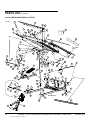
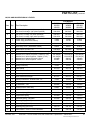
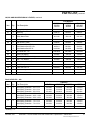
1
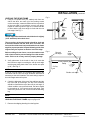
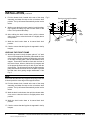
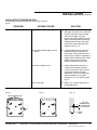
Mechanical Dock Levelers Models CM, WL and WS with HYDRA-CAM™ Lip Extension This manual applies to dock levelers manufactured beginning November 2013 with the serial numbers 61095303 and higher Do not install, operate or service this product unless you have read and understand the Safety Practices, Warnings, Installation and Operating Instructions contained in this User’s Manual. Failure to do so could result in death or serious injury. User’s Manual Installation, Operations, Maintenance and Parts Part No. 6004758M table of contents Introduction . ...............................................................2 Safety Signal Words....................................................2 Safety Practices..........................................................3 Owner's Responsibilities ............................................4 Ramp and Lip Grades ................................................5 Installation...................................................................6 Service Tools ............................................................12 Components..............................................................13 Operations Introduction ..........................................................14 Above Dock Level.................................................15 Below Dock Level.................................................17 Below Dock Level, End Loading ..........................18 Planned Maintenance................................................19 Adjustments...............................................................22 Lip Assist with HYDRA-CAM™..............................22 Main Spring Counterbalance................................23 Hold Down Assembly............................................24 Troubleshooting Guide..............................................26 Parts List Dock Leveler.........................................................28 ENERGY GUARD®...............................................34 Warranty....................................................................35 Corporate Contact ....................................................36 introduction Welcome and thank you for choosing this dock leveler for your material handling applications. This leveler is equipped with exclusive Posi-Trac® hold-down and Clean Frame® design. This dock leveler may be equipped with the optional ENERGY GUARD® dock leveler sealing system. This User’s Manual contains information that you need to safely install, operate, maintain and identify parts for the dock leveler. Please read and follow this User’s Manual when installing the dock leveler. safety SIGNAL WORDS You may find safety signal words such as DANGER, WARNING, CAUTION or NOTICE throughout this User’s Manual. Their use is explained below: This is the safety alert symbol. It is used to alert you to potential personal injury hazards. Obey all safety messages that follow this symbol to avoid possible death or injury. Indicates an imminently hazardous situation which, if not avoided, will result in death or serious injury. Indicates a potentially hazardous situation which, if not avoided may result in minor or moderate injury. Indicates a potentially hazardous situation which, if not avoided, could result in death or serious injury. Notice is used to address practices not related to personal injury. 2 6004758M — CM, WL and WS Series with HYDRA-CAM™ Lip Extension — SafeTFrame™ ©2013 4Front Engineered Solutions, Inc. November 2013 safety practices Read these safety practices before installing, operating, or servicing the dock leveler. Failure to follow the safety practices could result in death or serious injury. If you do not understand the instructions, ask your supervisor to explain them to you or call your authorized 4Front Engineered Solutions, Inc. distributor. OPERATION Use of dock leveler restricted to trained operators. Do not use this unit to service vehicles outside of its intended working range which is 12" above dock and 12" below dock (15" above dock and 12" below dock for 10' models). Do not operate the dock leveler when anyone is in front of it. Follow procedures on placard(s) posted near dock leveler. Stay clear of the dock leveler when it is moving. STAY CLEAR OF HINGES AT ALL TIMES. Do not use hands to position dock leveler ramp or lip, or to store dock leveler. Do not use a fork truck or other material handling equipment to lower the ramp. Before chocking wheels, or engaging the vehicle restraint, dump all air from the air ride suspensions and set the parking brake. INSTALLATION, MAINTENANCE AND SERVICE Service of dock levelers restricted to trained personnel. Place barricades on the dock floor around the dock leveler pit and in the driveway in front of the pit while installing, maintaining or repairing the dock. Do not operate the dock leveler when anyone is standing in front of the dock leveler unless they are securing the maintenance strut. Do not enter pit or do any maintenance or repair under dock leveler unless leveler is securely supported by maintenance strut. Failure to follow these instructions could result in death or serious injury to operators and/or bystanders. Do not use the dock leveler if it appears damaged or does not operate properly. Inform your supervisor immediately. Do not stand in the driveway between the dock leveler and the backing vehicle. Chock vehicle wheels or lock vehicle into place with vehicle restraining device and set brakes before loading or unloading. Visually check that the lip is supported by the vehicle floor or the lip is supported by both lip keepers before driving on the ramp. Store the dock leveler at dock level with lip in both lip keepers after use. Ensure lip avoids contact with vehicle sides and cargo. If lip does not lower to vehicle bed, reposition vehicle. Move all equipment, material or people off the dock leveler and store the dock leveler before allowing the vehicle to pull out. Do not walk on lip to lower the dock leveler. November 2013 6004758M — CM, WL and WS Series with HYDRA-CAM™ Lip Extension — SafeTFrame™ ©2013 4Front Engineered Solutions, Inc. 3 owner’s responsibilities The owner’s responsibilities include the following: The owner should recognize the inherent danger of the interface between dock and transport vehicle. The owner should, therefore, train and instruct operators in the safe use of dock leveling devices. When a transport vehicle is positioned at the dock, there shall be at least 4" of overlap between the front edge of the lip of the dock leveler and the edge of the floor or sill of the transport vehicle. Nameplates, cautions, instructions and posted warnings shall not be obscured from the view of operating or maintenance personnel for whom such warnings are intended. Manufacturer’s recommended periodic maintenance and inspection procedures in effect at time of shipment shall be followed and written records of the performance of these procedures should be kept. A dock leveler that is structurally damaged or has experienced a sudden loss of support while under load, such as might occur when a transport vehicle is pulled out from under the dock leveler, shall be removed from service, inspected by the manufacturer’s authorized representative and repaired as needed before being placed back in service. The owner shall see that all nameplates, caution and instruction markings or labels are in place and legible and that the appropriate operating and maintenance manuals are provided to users. Modifications or alterations of dock leveling devices shall be made only with written permission of the original manufacturer. When industrial vehicles are driven on and off transport vehicles during the loading and unloading operation, the brakes on the transport vehicle shall be applied and wheel chocks or positive restraints that provide the equivalent of wheel chocks engaged. The dock leveler should never be used outside its vertical working range or outside the manufacturer’s labeled rated capacity. It must also be compatible with the loading equipment and other conditions relating to the dock. 4 6004758M — CM, WL and WS Series with HYDRA-CAM™ Lip Extension — SafeTFrame™ ©2013 4Front Engineered Solutions, Inc. November 2013 ramp and lip grades Ramp grade Lip grade Ramp and lip grades, % for each dock leveler length Lip Ramp Lip Ramp Lip 15.0 --- --- --- --- 13.9 7.5 12.0 10.0 8.0 19.1 16.2 13.3 12.6 9.8 7.0 14.2 12.1 10.0 7.9 5.8 3.7 11.4 9.7 8.0 5.0 3.4 1.7 6.0 4.0 2.0 10.5 7.8 5.0 4.2 1.5 -1.3 7.9 5.8 3.8 1.6 -0.5 -2.5 6.3 4.7 3.0 -0.0 -1.6 3.3 0.0 -2.0 -4.0 -6.0 2.2 -0.5 -3.3 -6.0 -4.0 -6.8 -9.6 -12.4 -4.6 -6.7 -8.8 -10.8 -4.6 -17.2 -20.4 -18.6 1.3 -0.3 -2.0 -3.6 -4.9 -6.6 -8.3 -9.9 -8.0 -10.0 -12.0 -8.8 -11.6 -14.4 -15.2 -18.0 -20.9 -12.9 -15.1 -17.2 -16.8 -15.0 -13.3 -5.3 -7.0 -8.6 -11.6 -13.3 -15.0 6' Leveler 8' Leveler Ramp and lip grade, 4° lip bend, 16" lip. November 2013 10' Leveler Above Dock Ramp Vehicle bed position from dock, (in.) Below Dock Below Dock Above Dock Vehicle bed position from dock, (in.) Ramp and lip grades, % for each dock leveler length 6' Leveler 8' Leveler 10' Leveler Ramp Lip Ramp Lip Ramp Lip 15.0 --- --- --- --- 14.7 2.0 12.0 10.0 8.0 20.5 17.6 14.8 7.7 4.9 2.1 15.3 13.2 11.1 2.6 0.5 -1.6 12.2 10.5 8.8 -0.4 -2.1 -3.8 6.0 4.0 2.0 11.9 9.2 6.4 -0.7 -3.4 -6.2 9.0 6.9 4.8 -3.6 -5.7 -7.8 7.2 5.5 3.8 -5.4 -7.1 -8.8 0.0 -2.0 -4.0 -6.0 3.6 0.9 -2.1 -4.7 -9.0 -11.8 -14.6 -17.4 2.7 0.6 -1.4 -3.5 -9.9 -12.0 -14.1 -16.2 2.2 0.5 -1.1 -2.8 -10.4 -12.1 -13.8 -15.5 -8.0 -10.0 -12.0 -7.4 -10.2 -13.0 -20.3 -23.2 -26.1 -5.6 -7.7 -9.8 -18.3 -20.5 -22.7 -4.5 -6.1 -7.8 -17.2 -18.9 -20.6 Ramp and lip grade, 7° lip bend, 16" lip. 6004758M — CM, WL and WS Series with HYDRA-CAM™ Lip Extension — SafeTFrame™ ©2013 4Front Engineered Solutions, Inc. 5 installation PIT CHECK 1. Inspect the pit and remove all loose trash and construction debris. Prepare the rear of the pit for the leveler mounting feet. Using a chisel, remove any high spots visible within 6" of the rear wall below the rear curb angle. Verify that the pit matches the pit details for your leveler. See the installation troubleshooting on page 11 if the pit varies from the specification. See Fig. 12. leveler CHECK Before installing the dock leveler, read and follow the Safety Practices on page 3 and the operating instructions on pages 14-18. Failure to follow the safety practices could result in death or serious injury. Fig. 1 1. Visually check that all rear hinge pins, cotter pins, and kliprings are in place. 2. Visually check that the lip pin retainers are in place on both ends of the lip rod. 3. Visually check that both the lip maintenance bar and maintenance strut are undamaged and pins securely attached. 4. Visually check that the foot assemblies at the rear of the leveler are in place and undamaged. INSTALLATION 1. 4" x 4" steel shims are to be placed under the safety leg rests, D84 spring bracket, the outboard end of the D84 mounting plate, and the maintenance strut bracket at the front of the frame. See Fig. 1 and step 13. 2. Hold the leveler closed with shipping banding securing the lip plate to the frame. Install two load centering eye bolts into the front and rear of the top plate and hoist the leveler into the pit. The dock leveler should not be lifted in any other manner when placed into the pit. See Fig. 2. NOTE: Shim under front frame for all sizes of dock levelers in all shim locations shown. Fig. 2 30˚ (Min. angle) Inadequate lifting equipment or practices can cause a lifted load to fall unexpectedly. Make sure lifting chain or other lifting devices are in good condition and have a rated capacity of at least 3500 lbs. for the lifting angle used. Never allow anyone to stand on or near dock leveler when it is being lifted or placed into the pit. Stand clear of the dock leveler when it is being placed into the pit. Failure to follow this warning can allow the dock leveler to fall, tip, or swing into people, resulting in death or serious injury. 3. Position the dock leveler in the pit so that the gaps along both sides of the leveler are equal (±1/8") and the rear of the leveler frame touches the rear pit curb angle. See Fig. 4. NOTE: The rear frame angle should be about 3/4" lower than the pit curb angle before leveling. This is normal. Do not finish weld the rear angle until after performing the Leveling The Front Frame steps on pages 8-9. 6 NOTE: If the pit width conforms to the certified pit drawing, there be a 1/8" gap between the ends of the dock leveler's rear frame angle and the pit side curb angles. If this is not the case, the ends of the rear frame angle may require trimming to allow the gaps along both sides of the leveler to be equal (±1/8"). 6004758M — CM, WL and WS Series with HYDRA-CAM™ Lip Extension — SafeTFrame™ ©2013 4Front Engineered Solutions, Inc. November 2013 Raises rear angle installation, continued LEVELING THE REAR FRAME 4. Using a 1/2" square drive (1/2" ratchet) work from one side to the other, turn each (4) of the leveling screws on the rear angle, counterclockwise until the top surface of the rear angle is level with the rear pit curb angle. Repeat on each leg until all legs are in contact with the pit floor and the top frame angle is flush with the rear curb angle. See Fig. 3. Fig. 3 Raises rear angle Leg adjustment The rear edge of the dock leveler should be level or slightly (1/16" maximum) below dock level. The top surface of the dock leveler should be level and a smooth transition with the dock floor curb steel. The front end should be level and parallel with the rear frame angle for proper operation. Unequal shimming of the front supports may be required to obtain a level front edge. Before welding the rear frame, cover the weather seals with a sheet of steel to prevent setting fire to the weather seals. Failure to do so may result in property damage. 5. Verify placement of the leveler in the pit is such that the rear frame angle is touching the rear pit curb angle and the gaps along both sides of the leveler are equal (±1/8"). See Fig. 4. NOTE: If the pit is out-of-square, the resulting gap between the rear frame and the rear curb angle should be shimmed as necessary at the weld locations. Use steel shim(s) equal to the weld length and weld in place. Fig. 4 Rear frame angle Rear Leg pit curb angle adjustment Evenly spaced gaps Ramp Pit side curb angle 6. Check the alignment of the top of the subframe and the top of the rear pit curb angle. The top of the subframe should be flush with the top of the rear pit curb angle. If a flush condition can not be achieved, the frame should be a maximum of 1/16" lower than the curb angle. Tack weld in four places min. 3/8", one at or near each leveling leg. NOTE: Do not finish weld the rear angle until after performing the Leveling The Front Frame steps on pages 8-9. 7. Remove the shipping banding from the lip plate. November 2013 6004758M — CM, WL and WS Series with HYDRA-CAM™ Lip Extension — SafeTFrame™ ©2013 4Front Engineered Solutions, Inc. 7 installation, continued 8. Pull the release chain, located at the rear of the ramp assembly, and allow the ramp to rise to its above dock position. The lip will extend automatically as the leveler raises. 9. Walk out onto the dock leveler, lowering it until the safety legs contact the safety leg rests on both sides of the frame. The lip should fall slowly. 10. After walking the dock leveler down, pull the release chain once more to raise the leveler to a slightly above dock position. 11. Walk the dock leveler down to its stored dock level position. Fig. 5 Bevel groove weld locations 5" 5" 2-1/2" 5" 2-1/2" 5" 2-1/2" Frame uprights 5" 2-1/2" 5" Pit rear curb angle Rear hinge assembly 12. Check to ensure that the lip plate is supported in the lip keepers. leveling the front frame 13. With the lip stored in the lip keepers, place 4" x 4" steel shims of the appropriate thickness underneath the front of the leveler subframe, below the D84 spring, at the end of the D84 mounting plate, and the maintenance strut support. These shims should be flush with the front of the leveler frame, below or behind the lip keepers and of the proper thickness until top of deck is level with the dock surface. The shims at the end of the D84 mounting plate should be flush with the end of the plate to prevent the D84 chain from getting caught underneath it. See Fig. 6. NOTE: Ensure that the D84 shim fully supports the spring mount and is lined up with the outer edge of the support bracket. 14. Pull the release chain, located at the rear of the ramp assembly, and allow the ramp to rise to its above dock position. The lip will extend automatically as the leveler raises. 15. Walk the dock leveler down, then pull the release chain once more to raise the leveler to a slightly above dock position. 16. Walk the dock leveler down to its stored dock level position. 17. Check to ensure that the lip plate is supported in the lip keepers. 8 6004758M — CM, WL and WS Series with HYDRA-CAM™ Lip Extension — SafeTFrame™ ©2013 4Front Engineered Solutions, Inc. November 2013 installation, continued 18. To ensure that the ramp will be flush with the dock floor (where the overhead door makes contact) under normal operation proceed with steps 19-24. 19. Pull the release chain located at the rear of the ramp and allow the ramp to raise, but release the chain before the lip starts to extend. Fig. 6 Lip keepers not parallel to lip Improper Installation 20. Walk forward to the front of the ramp section of the dock leveler. Your weight will force the ramp down to its dock level (stored) position with the lip supported by both lip keepers. 21. When you step off the ramp, it may raise slightly. Adjust shims under the front of the both subframe members, below the safety leg supports and behind the lip keepers, until the top of the ramp is at the desired floor level. Proper Installation 22. Ensure the safety legs are centered on the safety leg posts. If not, adjust the frame runners as necessary. Tack weld the shims together and to the dock leveler subframe and front pit curb angle. 23. Check the shim height by repeating steps 19 and 20. When you step off, the top of the ramp should be at the desired floor level. If the ramp did not return to a position level with the dock floor, add or subtract shims as required. Then repeat steps 19 and 20. Lip keepers parallel to lip NOTE: Shims must be placed under the maintenance post bracket, below the safety leg supports, under D84 spring, frame bracket and behind the lip keepers. The shims at the end of the D84 mounting plate should be flush with the end of the plate to prevent the D84 chain from getting caught underneath it. On 18" and 20" lips, shims must also be welded in between the lip keepers and the vertical face of the curb angle. Before welding the dock leveler permanently into the pit, check the frame alignment again, to ensure that the lip keepers are parallel to the lip. See Fig. 6. Shimming of the frame members to a point where the front and rear are not parallel to each other will cause excessive float on one side of the ramp. The number of shims placed under the front frame will vary depending upon the “runout” in the poured pit and the desired location of the ramp when it is in dock level position. finish welding 24. After verifying that both sides of the dock leveler are evenly spaced to the pit sides and the top edge of the rear frame angle is flush to a max. 1/16" below the rear curb angle, weld the rear frame angle to the rear curb angle using 1/4" bevel joint weld in the grooves provided. Shown in Fig. 5. November 2013 6004758M — CM, WL and WS Series with HYDRA-CAM™ Lip Extension — SafeTFrame™ ©2013 4Front Engineered Solutions, Inc. 9 installation, continued 25. After the rear hinge angle is welded check that all leveling feet are in contact with the floor of the pit. Once all feet (4) are in contact with the floor. Torque each shimless leveling leg to 25-40 ft.-lbs. counterclockwise. Fig. 7 26. Weld all front shims solidly together and to the leveler subframe and to the front pit curb angle with 1/4” fillet welds. 27. Raise the dock leveler, remove and discard the cotter pins from toe guards on both sides of the leveler. Ensure telescopic toe guards (optional) move freely and do not bind. See Fig. 7. Store the dock leveler. 28. Perform the quarterly maintenance steps on page 19 in this manual. 29. Cycle the leveler four times going through the operational steps described on pages 14-18. Refer to all steps on pages 26-27 if any operational problems are encountered. 30. Mount the bumpers to the face of the dock. See Fig. 8. Improper installation of anchoring devices or installation into aged or unsound concrete could result in death or serious injury. 31. Permanently mount the dock leveler warning and operating placard on the wall near the dock leveler. See Fig. 9. Make sure the customer gets the user’s manuals and is properly trained. 32. Optional (where applicable), install rear angle cap plugs (part number 6004488) into adjustment socket holes. Press cap flush with top surface to rear angle. Remove shipping cotter pins Fig. 8 3/8" side of pit to side of bumper mounting plate 3/4" dia. anchor bolt, field installed, supplied by others 1/4" Full length of bumper mounting plate (Vertical down weld is not acceptable) Vertical bumper mounting angle Laminated bumper Fig. 9 WARNING and OPERATING INSTRUCTION placard 10 6004758M — CM, WL and WS Series with HYDRA-CAM™ Lip Extension — SafeTFrame™ ©2013 4Front Engineered Solutions, Inc. November 2013 installation, continued installation troubleshooting The following procedures apply after the leveler is level in the pit. PROBLEM POSSIBLE CAUSE 1)Leveler will not fit properly in pit. Fig. 10 SOLUTION a) Pit is out of square with the sides. a) Align the sides of the leveler so that both sides are equal (±1/8"). With the leveler's rear frame angle touching the rear curb angle, any gaps between the frame and the rear curb angle must be filled with steel shims of appropriate thickness and length equal to the frame's beveled weld locations. See Fig. 10. b) One side and rear angle is out of square. b) If the gap between the leveler and the side of the pit is less than 1/2" at any point, the performance of the leveler may be impaired, especially if weatherseal is attached to the leveler. Please consult 4Front Technical Services should this be the case. c) Pit floor irregular in rear. c) If large deformations exist in the concrete work, attempt to flatten out the rough surface using a chisel or grinder to take out the large obstructions. The rear leveling legs can be installed on out of plane surfaces up to 1/8" at each leg. See Fig. 12. d)Pit is too deep. d) Weld 4" x 4" shims to the bottom of the adjustable legs. Fig. 11 Fig. 12 Shim and weld flush Equal gap November 2013 1/8" max allowable step no greater than 1" x 3" in size 6" contact zone 6004758M — CM, WL and WS Series with HYDRA-CAM™ Lip Extension — SafeTFrame™ ©2013 4Front Engineered Solutions, Inc. 11 service tools Fig. 13 Read and follow the Safety Practices on page 3 of this manual before doing any service or repair to the dock leveler. RAISE Maintenance strut before climbing into the dock leveler pit or doing any maintenance or repair under the dock leveler. Failure to follow these instructions could result in death or serious injury. 1 2 3 maintenance strut 1. To raise the maintenance strut: a. Pull the hold down release chain to raise the dock leveler to the full above dock position b. Lift the maintenance strut up and forward. Fig. 14 c. Allow it to drop down into the locked position. See Fig. 13 2. To lower the maintenance strut: a. Lift the maintenance strut straight up. b. While holding it up, push it back. It will then lower to the stored position. lip maintenance bar 1. To Raise the lip maintenance bar: a. Support the lip manually and swing up the lip maintenance bar so the lip will rest on it. Ensure the lip maintenance bar is fully raised before releasing the lip. See Fig. 14. 2. To release the lip maintenance bar: a. Support the lip manually and pull the lip maintenance bar down. LIP WILL DROP without manual support. Ensure your head and fingers are away from the lip and any moving parts. See Fig. 15. 12 Fig. 15 6004758M — CM, WL and WS Series with HYDRA-CAM™ Lip Extension — SafeTFrame™ ©2013 4Front Engineered Solutions, Inc. November 2013 components The main components of the dock leveler are shown below. See the Parts List for specific part numbers. Fig. 16 Safety leg Lip plate hinge Safety leg Lip plate Lip maintenance bar Adjusting nut Toe guards Main springs Lip extension spring Hold down assy. Maintenance strut Subframe D84 spring Safety leg rests Lip keepers November 2013 6004758M — CM, WL and WS Series with HYDRA-CAM™ Lip Extension — SafeTFrame™ ©2013 4Front Engineered Solutions, Inc. 13 operations INTRODUCTION Before operating the dock leveler, read and follow the Safety Practices on page 3. Use of dock leveler restricted to trained operators. Follow procedures on placard posted near dock leveler. DO NOT USE DOCK LEVELER IF IT LOOKS BROKEN, OR DOES NOT SEEM TO WORK RIGHT. Inform your supervisor immediately. Before chocking wheels or engaging vehicle restraint, dump air from air ride suspensions and set parking brake. Always be certain that the vehicle is properly restrained, before loading or unloading. VISUALLY INSPECT vehicle restraint to make sure vehicle does not pull away unexpectedly. Failure to do so could result in death or serious injury. Before pulling release ring ensure lip avoids vehicle sides and cargo. If the lip does not lower to the vehicle bed, reposition vehicle. Never walk on leveler lip to lower dock leveler. Visually check that the lip is supported by the vehicle floor or the ramp is supported by both lip keepers before driving or walking on the ramp. The dock leveler is designed to span and compensate for space and height differences between a loading dock and freight carrier to allow safe, efficient freight transfers. The dock leveler uses a hold down mechanism to position the ramp. Pulling and holding the release chain allows springs to raise the ramp. Walking out onto the ramp causes the ramp to lower. A mechanical linkage extends the dock leveler lip as the ramp is being raised from its stored position. When the leveler is lowered the extended lip rests on the trailer floor forming a bridge. After loading, pulling and holding the release chain allows the ramp to raise. The lip will retract as the leveler is raised. Walking out onto the ramp lowers the leveler to the stored (dock level) position. With the dock leveler in the stored position,lip keepers support the dock leveler ramp at a position level with the dock floor. For below dock loads the safety legs can be retracted by pulling the below dock chain, located near the front of the deck before the deck lowers past dock level. Always return the dock leveler to its dock level (stored) position before allowing the vehicle to leave the dock. If the vehicle pulls away before the dock leveler is stored, the lip will fall to its pendant position and may not be supported by the lip keepers. In addition, failure to properly store the dock leveler may leave the leveler in a position below the level of the dock floor. These conditions may result in unexpected drop of personnel or material handling equipment and result in death or serious injury. Failure to follow these instructions could result in death or serious injury to operators and/or bystanders. If the vehicle unexpectedly pulls away leaving the dock leveler unsupported, the maximum drop is as follows: 1) If the leveler is above dock it will fall approximately 2" below dock floor level. 2) If the leveler is below 2" below dock level it will fall to full below dock level. 14 6004758M — CM, WL and WS Series with HYDRA-CAM™ Lip Extension — SafeTFrame™ ©2013 4Front Engineered Solutions, Inc. November 2013 operations — above dock level Use these instructions for normal operations, when the height of the vehicle is above the loading dock. Fig. 17 Always secure the vehicle with a vehicle restraint or wheel chocks before operating the dock leveler. Do not operate dock leveler with anyone standing on or in front of it. Do not lift the leveler lip by hand. Always keep hands and feet clear of all moving parts. Always restore the leveler to its safe dock level position with the lip supported in both lip keepers after servicing the vehicle. raising the leveler 1. Before operating the dock leveler, secure the vehicle with a vehicle restraint or wheel chocks. See Fig. 17. Fig. 18 2. To raise the leveler, pull and hold the hold-down release ring at the rear. When the leveler is fully raised, the lip will automatically extend. See Fig. 18. If the lip does not extend fully do not lift by hand. Restore the leveler to dock level and try again. If lip still does not extend fully, the dock leveler requires maintenance or adjustment. Notify your supervisor. Do not use the leveler until it has been repaired. Failure to comply could result in death or serious injury. November 2013 6004758M — CM, WL and WS Series with HYDRA-CAM™ Lip Extension — SafeTFrame™ ©2013 4Front Engineered Solutions, Inc. 15 operations — above dock level, continued 3. When the lip is fully extended, release the ring. Walk forward to the front of the ramp. The dock leveler will lower until the lip is resting on the vehicle. See Fig. 19. Fig. 19 Never walk on leveler lip to lower dock leveler. storing leveler 1. To return the leveler to the stored position, gently pull the hold-down release ring to raise the leveler from the vehicle floor and allow the lip to fall. See Fig. 20. If the lip does not fall to the stored position, the dock leveler requires maintenance or adjustment. Notify your supervisor. Do not use the dock leveler until it has been repaired. Failure to comply could result in death or serious injury. Fig. 20 2. When the lip is fully retracted and clear of the vehicle, walk forward to the front of the ramp. The dock leveler will lower until the lip is resting in the lip keepers. See Fig. 21. Fig. 21 16 6004758M — CM, WL and WS Series with HYDRA-CAM™ Lip Extension — SafeTFrame™ ©2013 4Front Engineered Solutions, Inc. November 2013 operations — below dock level Use these instructions when the height of the vehicle is below the loading dock. Fig. 22 Always secure the vehicle with a vehicle restraint or wheel chocks before operating the dock leveler. Do not operate dock leveler with anyone standing on or in front of it. Do not lift the leveler lip by hand. Always keep hands and feet clear of all moving parts. Always restore the leveler to its safe dock level position with the lip supported in both lip keepers after servicing the vehicle. 1. To raise the leveler, pull the hold-down release ring (at the rear of the leveler). When the leveler is fully raised, the lip will automatically extend. See Fig. 22. Fig. 23 2. When the lip is fully extended, walk forward to the front of the ramp. Pull the safety leg release ring at the front of the leveler. The dock leveler will lower to the below dock position with the lip resting on the vehicle. See Fig. 23. storing leveler 1. To return the leveler to the stored position, gently pull the hold-down release ring to raise the leveler from the vehicle floor and allow the lip to fall. See Fig. 24. Fig. 24 If the lip does not fall to the stored position, the dock leveler requires maintenance or adjustment. Notify your supervisor. Do not use the dock leveler until it has been repaired. Failure to comply could result in death or serious injury. 2. When the lip is fully retracted and clear of the vehicle, walk forward to the front of the ramp. The dock leveler will lower until the lip is resting in the lip keepers. See Fig. 25. Fig. 25 November 2013 6004758M — CM, WL and WS Series with HYDRA-CAM™ Lip Extension — SafeTFrame™ ©2013 4Front Engineered Solutions, Inc. 17 operations — below dock level, End loading Use these instructions when end loading a vehicle which is lower than the loading dock. Fig. 26 Always secure the vehicle with a vehicle restraint or wheel chocks before operating the dock leveler. Do not operate dock leveler with anyone standing on or in front of it. Do not lift the leveler lip by hand. Always keep hands and feet clear of all moving parts. Always restore the leveler to its safe dock level position with the lip supported in both lip keepers after servicing the vehicle. 1. Gently pull the hold-down release ring until the leveler is about 6" above dock level. See Fig. 26. Fig. 27 2. Walk towards the front of the dock leveler. Pull the safety leg release ring to retract the safety legs and extend the lip ahead of the lip keepers. The dock leveler will lower to the below dock position. See Fig. 27. storing leveler 1. To return the leveler to the stored position, gently pull the hold-down release ring to raise the leveler from the vehicle floor and allow the lip to fall. See Fig. 28. Fig. 28 If the lip does not fall to the stored position, the dock leveler requires maintenance or adjustment. Notify your supervisor. Do not use the dock leveler until it has been repaired. Failure to comply could result in death or serious injury. 2. When the lip is fully retracted and clear of the vehicle, walk forward to the front of the ramp. The dock leveler will lower until the lip is resting in the lip keepers. See Fig. 29. Fig. 29 18 6004758M — CM, WL and WS Series with HYDRA-CAM™ Lip Extension — SafeTFrame™ ©2013 4Front Engineered Solutions, Inc. November 2013 planned maintenance Be certain, before climbing into the dock leveler pit or doing any maintenance or repair under the dock leveler, that the maintenance strut is raised and supporting the top plate in case of emergency. Failure to do so could result in death or serious injury. WEEKLY 1.Inspect for debris in lip hinge. Clean as required. 2.Inspect for debris in rear hinge area of the leveler and between the sides and curb angles to ensure smooth operation. Clean as required. 3.Inspect the safety leg system for free operation, structural flaws, pull chain and return spring operation. 4.Inspect the operation of the telescopic toe guards (optional) to ensure they are not distorted or binding when operating the leveler. quarterly 1.Inspect all warning labels and placards. See page 21. Replace as necessary. 2.Clean out the inside of the pit area. 3.Inspect and lubricate all mechanical pivot points on the leveler with a light oil such as S.A.E. 30. See Fig. 30. Do not lubricate between the brake band and brake drum. 4.Clean the hold down rack and gear. Apply a light coat of S.A.E. 30 oil to the gear and all sides of the rack. Lubricate the spur gear axle by rotating the spur gear by raising or lowering the leveler until the 1/4" hole is visible on the gear next to the teeth. Apply a couple of drops of S.A.E. 30 oil into this hole. November 2013 Before servicing the dock leveler, read and follow the Safety Practices on page 3 and the operations sections of this manual. Failure to follow the Safety Practices could result in death or serious injury. quarterly (continued) 5.Check hold down for proper float as described on page 24. Make any adjustments required. 6.Inspect the main springs and pivot pin for excessive wear. 7.Inspect the lip push out arm and lip counterbalance assemblies for damage and check the chain and springs for elongation. 8.Inspect all welds under the leveler for fatigue or failure, particularly the lip plate hinge and top plate beams and front hinge bar. 9.Check the full operation of the leveler. Make any adjustments required. Before making any adjustments to the leveler mechanisms, be sure to clean, lube per instructions on this page and page 20, and operate leveler several times. 10.Lubricate the lip hinge tubes with molybdenum disulfide grease NLGI #2. Do not over grease. Stop when grease begins to ooze out of the hinge tube ends. Wipe off excess grease. 11. Inspect dock bumpers. Four inches (4") of bumper protection is required. Worn, torn, loose or missing bumpers must be replaced. 6004758M — CM, WL and WS Series with HYDRA-CAM™ Lip Extension — SafeTFrame™ ©2013 4Front Engineered Solutions, Inc. 19 planned maintenance, continued Fig. 30 Legend Symbol Description Lubricate - oil Light oil - SAE 30 Rear hinge pin Lubricate - grease Molybdenum disulfide NLGI #2 Cleaning (Location - frequency) Clean lip hinge area - weekly Visually inspect (Replace damaged or worn) (Typ.) Pivot points (Both sides and back) Rear hinges Clean as required Pit - 3 mo. (Three sides) Do not lubricate between the brake band and brake drum. 20 Clean gear axle and rack - 3 mo. 6004758M — CM, WL and WS Series with HYDRA-CAM™ Lip Extension — SafeTFrame™ ©2013 4Front Engineered Solutions, Inc. November 2013 planned maintenance, continued Every 90 days (quarterly) inspect all safety labels and tags to ensure they are on the dock leveler and are easily legible. If any are missing or require replacement, please your authorized 4Front Engineered Solutions, Inc. distributor. Fig. 31 921-217 6008485 (x2) 138-837 (x2) 921-117 921-074 921-070 6001946 WARNING AND OPERATION PLACARD (MOUNTED ON WALL NEAR LEVELER) November 2013 6004758M — CM, WL and WS Series with HYDRA-CAM™ Lip Extension — SafeTFrame™ ©2013 4Front Engineered Solutions, Inc. 21 adjustments — lip ASSIST with HYDRA-CAM™ Before servicing the dock leveler, always position traffic cones or a barricade behind the dock leveler to warn fork vehicle operators and pedestrians away from the leveler. Always position traffic cones or a barricade in front of the leveler to warn against vehicle traffic. Always notify a foreman or supervisor that you are working under the equipment. Always make sure that the maintenance strut is in the raised position before working under the dock leveler. Always make sure that the overhead door is securely held in the raised position. 1. Ensure that lip hinges have been greased and all other pivot pins have been lubricated. 2. Fully raise the leveler and extend the lip. The lip should remain fully extended. Check that all lip assist pivot points are lubricated with light oil. 3. If the lip starts to fall, increase the lip spring tension by turning the adjusting bolt clockwise. Securely tighten locknut after adjusting. Fig. 32 Bellcrank 4. Walk the leveler down approximately 12". The lip should start to drop very slowly. 5. If the lip does not start to fall, decrease the lip spring tension by turning the adjusting bolt counter clockwise. Securely tighten the locknut after adjusting. 6. Walk the leveler down an additional 6". The lip should fall to the pendant position. Further decrease lip spring tension if required. Securely tighten the locknut after adjusting. 7. After the lip spring has been properly adjusted, walk the leveler down to dock level. The lip should fall completely within 20 seconds. 8. Because the force of the Hydra-Shock is affected by temperature, the bellcrank has three mounting holes. The front of the Hydra-Shock is normally mounted in the outermost position. To adjust the Hydra-Shock, the lip must be pendant. If the lip falls too quickly, remove the spring clip and clevis pin and move it to a hole farther from the center of the bellcrank. If the lip falls too slowly, move the pin to the hole closer to the center of the bellcrank and secure with pin. NOTE: Before making any adjustments to the leveler mechanisms, be sure to clean, lube per instructions on page 19 and 20, and operate leveler several times. Three mounting holes Pivot plate Hydra-Shock Adjusting bolt Locknut Lip spring 22 6004758M — CM, WL and WS Series with HYDRA-CAM™ Lip Extension — SafeTFrame™ ©2013 4Front Engineered Solutions, Inc. November 2013 adjustments — main spring counterbalance The main spring should be adjusted so that the leveler raises enough to fully extend the lip, yet still be easy to walk down. NOTE: Make sure that the hold down is operating freely. Excessive drag from the hold down may cause the leveler to raise too slowly. NOTE: Before making any adjustments to the leveler mechanisms, be sure to clean, lube per instructions on page 19 and 20, and operate leveler several times. Make sure that the lip hinge and deck hinges are lubricated and are operating freely. Excessive friction in the lip or deck hinges can prevent the lip from raising easily. Extended springs contain stored energy. Never attempt to remove main springs without completely removing the load from the springs first. Do not remove the main springs until the leveler and the lip are safely supported by a suitable lifting device. Fig. 33 Adjusting nut Tools Required: 1-1/2" open end wrench 1. If the lip does not fully extend, turn the adjusting nut clockwise to increase the main spring tension. 2. If the leveler is too hard to walk down, turn the adjusting nut counter-clockwise to decrease the main spring tension. November 2013 6004758M — CM, WL and WS Series with HYDRA-CAM™ Lip Extension — SafeTFrame™ ©2013 4Front Engineered Solutions, Inc. 23 adjustments — hold down assembly The hold down uses a friction brake to hold the leveler in position. The brake is released to allow the leveler to raise and the lip to extend. Fig. 34 Brake housing Rack Spur gear Float spring housing Release lever Gear axle Brake band 3" Brake band tension adjusting nut 5" Subframe 24 Release lever adjusting nut 6004758M — CM, WL and WS Series with HYDRA-CAM™ Lip Extension — SafeTFrame™ ©2013 4Front Engineered Solutions, Inc. November 2013 adjustments — hold down assembly, continued NOTE: Before making any adjustments to the leveler mechanisms, be sure to clean, lube per instructions on page 19 and 20, and operate leveler several times. Do not lubricate between the brake band and brake drum. If the leveler raises without pulling the hold down release ring, inspect the gear teeth on the rack bar and pinion gear. Also make sure that the pinion gear is free to slide along the axle to engage the clutch teeth on the side of the brake drum assembly. If foreign material has accumulated on the gear axle it will interfere with free movement of the spur gear. Clean the axle and small compression spring which fits over the axle. If the leveler raises by itself, or if the leveler will not raise quickly when the hold down release ring is pulled, the hold down requires adjustment or replacement. To adjust the hold down to provide optimum performance the following adjustments are to be made in the sequence shown. 1.Clean the hold down rack and gears and apply a light automotive grease. Do not lubricate between the brake band and brake drum. To check the adjustment of the brake spring to provide proper hold down float: ● Pull the hold down release chain and hold until the lip fully extends. ● Engage the lip maintenance bar. ● Lower the leveler to dock level. ● Lift up on the leveler until the brake housing moves away from the float spring housing. ● Measure the brake housing extension distance when the brake starts to slip. Do not lubricate between the brake band and brake drum. When the dock leveler is forced upward, the brake should not slip until the brake housing has extended at least 1-1/2" away from the float spring housing. Tighten the brake band tension adjusting nut to increase the braking force if required. Do not tighten the brake spring to less than 2-1/2" long or the brake may not release properly. If slippage occurs in either the gears or the brake band before the float tube extends at least 1-1/2", or the brake will not hold, replace the hold down assembly. 2.Release Lever Adjusting Nut - The end of the release lever should be approximately 5" away from the chain guide assembly, as shown. Adjust the release lever adjusting nut to maintain the 5" distance. 3.Brake Band Tension Adjusting Nut - The brake spring applies tension to the brake band. The spring is factory set to 3" compressed length, as shown in Fig. 34. November 2013 6004758M — CM, WL and WS Series with HYDRA-CAM™ Lip Extension — SafeTFrame™ ©2013 4Front Engineered Solutions, Inc. 25 troubleshooting guide Be certain, before climbing into the dock leveler pit or doing any maintenance or repair under the dock leveler, that the maintenance strut is raised and supporting the top plate in case of emergency. Failure to do so could result in death or serious injury. Use the Troubleshooting Guide if ever the leveler fails to perform properly. Find the condition that most closely matches your situation, and make the recommended adjustments. PROBLEM 1. Leveler will not raise when release ring is pulled 2. Leveler cannot be walked down. 3. Lip plate will not fully extend when leveler is raised. 26 Before servicing the dock leveler, read and follow the Safety Practices on page 3 and the Operating Instruction section in this manual. NOTE: Before making any adjustments to the leveler mechanisms, be sure to clean, lube per instructions on page 19 and 20, and operate leveler several times. POSSIBLE CAUSE SOLUTION a) How down release chain is binding. a) Inspect release chain. b) Hold down is binding or rack is bent. b) Clean rack assy. and lubricate (Do not lubricate between the brake band and brake drum). If rack is bent, it must be replaced. c) Brake band dragging. c) Inspect brake band. Adjust hold down, if required, as shown on pages 24-25. d) Main springs require adjustment. d) Adjust spring tension, if required, as shown on page 23. a) Rack assy. is binding or bent. a) Clean rack assy. and lubricate. (Do not lubricate between the brake band and brake drum). If rack is bent, it must be replaced. b) Main spring over adjusted. b) Adjust spring tension, if required, as shown on page 23. a) Debris or corrosion in lip hinge. a) Clean and lubricate lip hinge. b) Debris or corrosion in rear hinge. b) Clean and lubricate rear hinge. c) Lip spring adjustment incorrect. c) Adjust lip spring as shown on page 24 and lubricate mechanism. d) Hold down not releasing freely. d) Adjust hold down, if required, as shown on pages 24-25. e) Main spring adjustment. e) Adjust main springs as shown on page 23. 6004758M — CM, WL and WS Series with HYDRA-CAM™ Lip Extension — SafeTFrame™ ©2013 4Front Engineered Solutions, Inc. November 2013 troubleshooting guide, continued PROBLEM POSSIBLE CAUSE SOLUTION 4. Lip plate will not extend at all when leveler is raised. a) Lip chain is disconnected. a) Inspect and repair as required. b) Lip hinge is binding. b) Clean and lubricate the lip hinge. 5. Lip falls before it can be walked down to the vehicle. a) Lip spring requires more tension. a) Adjust lip spring tension as shown on page 22. b) Front of Hydra-Shock is mounted in the cold weather position. b) Move the Hydra-shock front mounting pin as shown on page 22. c) Hydra-Shock missing or damaged. c) Replace Hydra-Shock. 6. Lip plate does not fall when leveler is in working range. a) Debris or corrosion in lip hinge. a) Clean and lubricate lip hinge. b) Lip spring is over-tensioned. b) Adjust lip as shown on page 22 and lubricate mechanism. 7. Leveler will not travel below dock. a)Safety legs or chain stuck or binding. a) Inspect safety legs and lubricate or repair and required. b) Hold down binding or rack is bent. b) Inspect hold down assy. and adjust, lubricate or replace as required. (Do not lubricate between the brake band and brake drum). If rack is bent it must be replaced. c) Main springs adjustment incorrect. c) Inspect main springs and adjust as required. See page 23. 8. Leveler travels below 2-1/2" below dock when lip is out of lip keepers. a) Safety legs stuck in retracted position. a) Inspect safety legs and lubricate or repair as required. Check that return spring is properly installed. 9. Leveler does not follow when vehicle floor moves down. a) Safety legs are engaging the frame. a) Retract safety legs and lubricate or repair as required. b) Hold down has insufficient float. b) Check float as shown on page 24 and adjust hold down, if required. a) Hold down requires adjustment or maintenance. a) Clean, adjust and lubricate hold down as shown on pages 19 and 24-25. Replace entire hold down assy. if leveler will not stay down after lubrication and adjustment. 10. Leveler will not stay down on vehicle bed or in stored position. November 2013 6004758M — CM, WL and WS Series with HYDRA-CAM™ Lip Extension — SafeTFrame™ ©2013 4Front Engineered Solutions, Inc. 27 parts list, continued CM, wl and WS series dock leveler Fig. 36 60 73 62 8 36 7 34 74 55 59 4 21 14 41 4 3 36 28 75 58 2 1 34 23 18 4 19 34 53 71 33 29 50 50 40 32 31 36 42 66 13 49 46 50 51 45 8 24 63 50 44 37 7 15 25 67 35 26 12 17 33 37 5 Top plate assy. 26 37 33 35 9 34 43 28 54 28 76 12 12 56 23 11 46 72 23 12 4 16 6 39 64 65 6 20 52 10 28 38 77 Frame assy. 28 68 57 58 70 69 61 78 6004758M — CM, WL and WS Series with HYDRA-CAM™ Lip Extension — SafeTFrame™ ©2013 4Front Engineered Solutions, Inc. November 2013 parts list, continued CM, wl and WS series dock leveler Part Number CM600 CM800 Item Qty. Part Description WS600 WS800 WL600 WL800 CM1000 WS1000 WL1000 1 1 1 Toe Guard, 2nd stage, left (when specified) Toe Guard, 2nd stage, right (when specified) 586-1659 586-1660 586-0440 586-0441 586-1045 586-1044 2 1 1 Toe Guard, 1st stage, left (when specified) Toe Guard, 1st stage, right (when specified) 586-1657 586-1658 586-0439 586-0438 586-1043 586-1042 3 1 1 Pusher Assy. (for safety legs) Pusher Assy. (below dock control) 3-4666 3-4799 3-4666 3-4799 3-4666 3-4799 4 4 Cotter Pin 1/8 x 3/4 231-341 231-341 231-341 5 1 Chain Assy. B.D.C. (below dock control) 8-9610 8-9610 8-9610 6 1 Maintenance Strut 600 - CP 586-2966 586-2966 586-2966 7 2 Weather Seal Mounting Strip (with rubber seal only) 328-897 328-898 328-898 8 2 2 2 2 Weather Seal - Narrow Projection - Rubber (1-1/4") Weather Seal - Wide Projection - Rubber (1-3/4") Weather Seal - Narrow Projection - Brush Weather Seal - Wide Projection - Brush 152-324(5ft) 152-325(5ft) 328-886 328-907 152-324(7ft) 152-325(7ft) 328-887 328-908 152-324(7ft) 152-325(7ft) 328-888 328-909 9 2 Hazard Stripe 138-837 138-837 138-837 10 1 Spring Guide Assy 3-5335 3-5335 3-5335 11 2 Cable Clamp 441-103 441-103 441-103 12 4 Chain Shackle 1/4" 442-800 442-800 442-800 13 1 Chain - Lip 586-1921 586-0052 586-1947 14 1 Decal, Maint Strut Danger 921-217 921-217 921-217 15 1 Bellcrank Weldment - HYDRA-CAM - CP 3-3332 3-3332 3-3332 16 1 Chain Stop 341-014 341-014 341-014 17 1 Lip Assist Bar - “HS” 328-685 328-685 328-685 18 1 HYDRA-SHOCK Plate Assy. 8-9043 8-9043 8-9043 19 1 Hydra-Shock 328-729 328-729 328-729 20 1 Extension Spring (D84) 333-029 333-029 333-029 21 1 Compression Spring 332-069 332-069 332-069 22 2 Extension Spring - Latch Bar 333-042 333-042 333-042 23 5 Retaining Ring (5304-75) 236-110 236-110 236-110 24 1 Retaining Ring (5304-50) 236-106 236-106 236-106 25 1 Retaining Ring (5304-100) 236-114 236-114 236-114 26 7 Plain Washer - 3/4 ID x 1/2 OD Hardened 234-143 234-143 234-143 November 2013 6004758M — CM, WL and WS Series with HYDRA-CAM™ Lip Extension — SafeTFrame™ ©2013 4Front Engineered Solutions, Inc. 29 parts list, continued CM, wl and WS series dock leveler, continued Part Number CM600 CM800 Item Qty. Part Description WS600 WS800 WL600 WL800 CM1000 WS1000 WL1000 27 1 User's manual 6004758 6004758 6004758 28 6 Plain Washer - 9/16" I.D. 234-260 234-260 234-260 29 1 Hex Bolt - 3/8" - 16 UNC x 1-1/4" lg 212-104 212-104 212-104 30 1 Hex Bolt - 3/8" x 3" lg 212-118 212-118 212-118 31 1 Bolt Rod Assy. - CP 3-4737 3-4737 3-4737 32 1 EL Rod Spacer 586-1999 586-1999 586-1999 33 5 Hex Nut - 3/8" Nylock 214-538 214-538 214-538 34 4 Clevis Pin - 1/2" DIA x 2-3/4" lg 231-502 231-502 231-502 35 2 Rue Ring 6006050 6006050 6006050 36 3 Spring Pin 231-123 231-123 231-123 37 9 Plain Washer 3/8" Bolt Size - 7/16" Hole 234-101 234-101 234-101 38 1 Danger Label (Entering Pit) 921-070 921-070 921-070 39 1 Danger Label 921-074 921-074 921-074 40 1 Danger Label (Springs) 921-117 921-117 921-117 41 1 Pin - 3/4" Dia x 2-7/8" Gr-Rng 583-0003 583-0003 583-0003 42 1 DU Bushing: 16DU08 821-034 821-034 821-034 43 1 Bellcrank Spacer 586-3031 586-3031 586-3031 44 1 DU Bushing - Flanged: 16FDU08 821-033 821-033 821-033 45 1 EL - Yoke Pin 586-1998 586-1998 586-1998 46 4 Pin - 3/4" Dia 586-1467 586-1467 586-1467 47 1 Pin - 3/4" Dia x 2-1/18" Gr-Rng 586-0003 586-0003 586-0003 48 1 EL - Latch Bar Return Spring 333-045 333-045 333-045 49 1 Lift Arm Assy. 50 4 Plain Washer - 1" Bolt Size - 1-1/16" Hole Size 234-161 234-161 234-161 51 1 Hex Nut 1" - 8 214-341 214-341 214-341 52 1 Pin - 1" Dia 5-1/2" Gr-Rng 586-1070 586-1070 586-1070 53 1 Upper Safety Leg Assy. 6002984 6002984 6002984 54 1 Rear Chain 586-3016 586-3020 586-3120 55 1 Lip Plate Maint. Bar 586-2969 586-2969 586-2969 30 Consult Factory 6004758M — CM, WL and WS Series with HYDRA-CAM™ Lip Extension — SafeTFrame™ ©2013 4Front Engineered Solutions, Inc. November 2013 parts list, continued CM, wl and WS series dock leveler, continued Part Number CM600 CM800 Item Qty. Part Description WS600 WS800 WL600 WL800 CM1000 WS1000 WL1000 56 1 Spring Adjusting Loop 586-3009 586-3009 586-3009 57 1 Serial tag 6009761 6009761 6009761 58 2 2 Serco Name Plate Kelley Name Plate 824-002 921-140 824-002 921-140 824-002 921-140 59 1 Placard 6001946 6001946 6001946 60 2 User Warning Label 6008485 6008485 6008485 61 1 1 1 Rear WeatherSeal CP 6ft. Rear WeatherSeal CP 6.5ft. Rear WeatherSeal CP 7ft. 6015410 6015411 6015594 6015410 6015411 6015594 6015410 6015411 6015594 62 1 S/L Guide Arm - CP 586-2959 586-2959 586-2959 63 1 Safety Leg Spring 333-055 333-055 333-055 64 4 Clevis Pin 1/2" DIA x 2-1/4 lg 231-506 231-506 231-506 65 4 SAE - 1/2" Washer 234-260 234-260 234-260 66 1 SQ. Nut 3/8-16 UNC Plain 214-826 214-826 214-826 67 1 Latch Tab Hydra 586-1384 586-1384 586-1384 68 5 Cotter Pin 5/32 x 2 6001832 6001832 6001832 69 4 Foot Assembly 6002915 6002915 6002915 70 1 Hold down chain assy. 8-9611 8-9612 8-9612 dock leveler — 600 Capacity Item Qty. Part Description 30,000 35,000 40,000 45,000 71 3 Main Spring, Extension - 6 ft x 16 in Main Spring, Extension - 6 ft x 18 in Main Spring, Extension - 6 ft x 20 in 333-049 333-049 333-054* 333-049 333-049 333-054* 333-049 333-054* 333-054* 333-049 333-054* 333-054* 71 2 Main Spring, Extension - 6.5 ft x 16 in Main Spring, Extension - 6.5 ft x 18 in Main Spring, Extension - 6.5 ft x 20 in 333-054 333-054 333-054 333-054 333-054 333-054 333-054 333-054 333-054 333-054 333-054 333-054 71 2 Main Spring, Extension - 7 ft x 16 in Main Spring, Extension - 7 ft x 18 in Main Spring, Extension - 7 ft x 20 in 333-054 333-054 333-054 333-054 333-054 333-054 333-054 333-054 333-054 333-054 333-054 333-054 Main Spring, Support Assembly 3-5073 3-5073 3-5073 3-5073 72 1 * Quantity — 2 November 2013 6004758M — CM, WL and WS Series with HYDRA-CAM™ Lip Extension — SafeTFrame™ ©2013 4Front Engineered Solutions, Inc. 31 parts list, continued dock leveler — 800 Capacity Item Qty. Part Description 30,000 35,000 40,000 45,000 71 2 1 2 1 2 1 Main Spring, Extension - 6 ft x 16 in 333-054 333-054 Main Spring, Extension - 6 ft x 16 in Main Spring, Extension - 6 ft x 18 in 333-054 333-054 Main Spring, Extension - 6 ft x 18 in — — Main Spring, Extension - 6 ft x 20 in 333-054 333-054 Main Spring, Extension - 6 ft x 20 in —— 333-054 333-049 333-054 333-049 333-054 333-049 333-054 333-049 333-054 333-049 333-054 333-049 71 2 1 2 1 2 1 Main Spring, Extension - 6.5 ft x 16 in Main Spring, Extension - 6.5 ft x 16 in Main Spring, Extension - 6.5 ft x 18 in Main Spring, Extension - 6.5 ft x 18 in Main Spring, Extension - 6.5 ft x 20 in Main Spring, Extension - 6.5 ft x 20 in 333-054 333-049 333-054 333-049 333-054 333-049 333-054 333-049 333-054 333-049 333-054 333-049 333-054 333-049 333-054 333-049 333-054 333-049 333-054 333-049 333-054 333-049 333-054 333-049 71 2 1 2 1 2 1 Main Spring, Extension - 7 ft x 16 in Main Spring, Extension - 7 ft x 16 in Main Spring, Extension - 7 ft x 18 in Main Spring, Extension - 7 ft x 18 in Main Spring, Extension - 7 ft x 20 in Main Spring, Extension - 7 ft x 20 in 333-054 333-049 333-054 333-049 333-054 333-049 333-054 333-049 333-054 333-049 333-054 333-049 333-054 333-049 333-054 333-049 333-054 333-049 333-054 333-049 333-054 333-049 333-054 333-049 1 Main Spring, Support Assembly 3-5073 3-5073 3-5073 3-5073 72 dock leveler — 1000 71 2 Main Spring, Extension - 6 ft x 16 in 1 333-054 333-049 333-054 333-049 333-054† 333-049 333-054† 333-049 2 Main Spring, Extension - 6 ft x 18 in 1 333-054 333-049 333-054 333-049 333-054† 333-049 333-054† 333-049 2 Main Spring, Extension - 6 ft x 20 in 1 333-054 333-049 333-054 333-049 333-054† 333-049 333-054† 333-049 71 2 Main Spring, Extension - 6.5 ft x 16 in 1 333-054 333-049 333-054 333-049 333-054† 333-049 333-054† 333-049 2 Main Spring, Extension - 6.5 ft x 18 in 1 333-054 333-049 333-054 333-049 333-054† 333-049 333-054† 333-049 2 Main Spring, Extension - 6.5 ft x 20 in 1 333-054 333-049 333-054 333-049 333-054† 333-049 333-054† 333-049 3 Main Spring, Extension - 7 ft x 16 in 333-054 333-054 333-054‡ 333-054‡ 3 Main Spring, Extension - 7 ft x 18 in 333-054 333-054 333-054‡ 333-054‡ 3 Main Spring, Extension - 7 ft x 20 in 333-054 333-054 333-054‡ 333-054‡ 1 Main Spring, Support Assembly 3-5254 3-5254 3-5254 3-5254 71 72 * Quantity — 2; †Quantity — 3; ‡Quantity — 4 32 6004758M — CM, WL and WS Series with HYDRA-CAM™ Lip Extension — SafeTFrame™ ©2013 4Front Engineered Solutions, Inc. November 2013 parts list, continued dock leveler — ALL Capacity Item Qty. Part Description 30,000 35,000 40,000 45,000 73 1 Lip Assembly - “L” - 6 ft x 16 in Lip Assembly - “L” - 6 ft x 18 in Lip Assembly - “L” - 6 ft x 20 in 3-0845 3-0846 3-0847 3-0848 3-0849 3-0850 3-0851 3-0852 3-0853 3-0854 3-0855 3-0856 1 Lip Assembly - “L” - 6.5 ft x 16 in Lip Assembly - “L” - 6.5 ft x 18 in Lip Assembly - “L” - 6.5 ft x 20 in 3-0863 3-0864 3-0865 3-0866 3-0867 3-0868 3-0869 3-0870 3-0871 3-0872 3-0873 3-0874 1 Lip Assembly - “L” - 7 ft x 16 in Lip Assembly - “L” - 7 ft x 18 in Lip Assembly - “L” - 7 ft x 20 in 3-0881 3-0882 3-0883 3-0884 3-0885 3-0886 3-0887 3-0888 3-0889 3-0890 3-0891 3-0892 2 Latch Assist Arm - 1-3/4" Tube - “L” 586-2272 586-2272 — — 2 Latch Assist Arm - 2-3/8" Tube - “L” — — 586-2638 586-2638 75 1 1 1 Lip Hinge Pin - 6 ft wide Lip Hinge Pin - 6.5 ft wide Lip Hinge Pin - 7 ft wide 586-0017 586-1494 586-0201 586-0017 586-1494 586-0201 586-0287 586-1495 586-0392 586-0287 586-1495 586-0392 76 1 1 1 1 1 1 1 1 1 Extension Spring, Lip - 6 ft x 16 in Extension Spring, Lip - 6 ft x 18 in Extension Spring, Lip - 6 ft x 20 in Extension Spring, Lip - 6.5 ft x 16 in Extension Spring, Lip - 6.5 ft x 18 in Extension Spring, Lip - 6.5 ft x 20 in Extension Spring, Lip - 7 ft x 16 in Extension Spring, Lip - 7 ft x 18 in Extension Spring, Lip - 7 ft x 20 in 333-043 333-044 333-044 333-043 333-044 333-044 333-043 333-044 333-044 333-043 333-044 333-044 333-043 333-044 333-044 333-043 333-044 333-044 333-043 333-043 333-044 333-043 333-044 333-044 333-043 333-044 333-044 333-043 333-043 333-044 333-043 333-044 333-044 333-043 333-044 333-044 77 1 Hold down rack 88786 88786 88786 88786 78* 1 Hold down assy 6013680 6013680 6013680 6013680 74 *Does not include item 77 hold down rack. November 2013 6004758M — CM, WL and WS Series with HYDRA-CAM™ Lip Extension — SafeTFrame™ ©2013 4Front Engineered Solutions, Inc. 33 PARTS LIST, continued optional energy guard® dock leveler sealinG system Fig. 37 10 11 13 12 9 7 3 4 5 1 6 2 Item DescriptionQuantityPart Number 6x6 6.5x6 6x7 6x8 6.5x8 7x8 6x10 6.5x10 7x10 6008228 6008229 6008230 6008231 6008232 6008233 6008234 6008235 6008236 1 2 3 4 5 6 7 8 9 10 11 12 13 34 5-1/2" Front seal 2 2 2 2 2 2 2 2 2 Vertical seal 2 2 2 2 2 2 2 2 2 6' Upper seal 2 2 2 8' Upper seal 2 2 2 10' Upper seal 2 2 2 Aluminum strip 53-1/2" 2 2 2 Aluminum strip 77-1/2" 2 2 2 Aluminum strip 101-1/2" 2 2 2 6' Lower seal 2 2 2 8' Lower seal 2 2 2 10' Lower seal. 2 2 2 Aluminum strip 6' upper 2 2 2 Aluminum strip 8' upper 2 2 2 Aluminum strip 10' upper 2 2 2 6' Serco rear seal 1 1 1 6.5' Serco rear seal 1 1 1 7' Serco rear seal 1 1 1 Tech screws (not shown) 6 6 6 8 8 8 10 10 10 Chain cup seal 2 2 2 2 2 2 2 2 2 3/4-10 Set screw 2 2 2 2 2 2 2 2 2 W/seal 600 W brush 2 2 2 2 2 2 W/seal 800 W brush 2 2 2 W/seal 600 W brush cut 2 2 2 Corner bulb seal 2 2 2 2 2 2 2 2 2 Transition angle seal (optional) 2 2 2 2 2 2 2 2 2 6004758M — CM, WL and WS Series with HYDRA-CAM™ Lip Extension — SafeTFrame™ ©2013 4Front Engineered Solutions, Inc. 6008166 6008173 6008167 6008169 6008171 6008175 6008177 6008179 6008168 6008170 6008172 6008174 6008176 6008178 6007674 6007675 6007676 000699 0392 6008249 328907 328908 328910 6009507 6008247 November 2013 limited warranty — mechanical dock leveler THIS LIMITED WARRANTY IS 4FRONT’S SOLE AND EXCLUSIVE WARRANTY WITH RESPECT TO THE DOCK LEVELER AND IS IN LIEU OF ANY OTHER GUARANTEES OR WARRANTIES, EXPRESS OR IMPLIED. 4FRONT warrants that this DOCK LEVELER will be free from flaws in material and workmanship under normal use for a period of one (1) year from the earlier of 1) 60 days after the date of initial shipment by 4FRONT, or 2) the date of installation of the DOCK LEVELER by the original purchaser, provided that the owner maintains and operates the DOCK LEVELER in accordance with this User’s Manual. Main Spring Warranty – All main springs are warranted to cover the cost of replacement parts and freight only for an extended period of four (4) years after the initial 1 year warranty period. Parts warranty – All spare parts or replacement parts are warranted to cover the cost of replacement parts and freight only for ninety (90) days from the date of shipment. In the event that this DOCK LEVELER proves deficient in material or workmanship within the applicable Limited Warranty period, owner shall so notify 4FRONT, and 4Front will, at its option: 1. Replace the DOCK LEVELER, or the deficient portion(s) thereof, without charge to the owner; or 2. Alter or repair the DOCK LEVELER, on site or elsewhere, without charge to the owner. This Limited Warranty does not cover any failure caused by improper installation, abuse, improper operation, negligence, or failure to maintain and adjust the DOCK LEVELER properly. Parts requiring replacement due to damage resulting from vehicle impact, abuse, or improper operation are not covered by this warranty. 4FRONT DISCLAIMS ANY RESPONSIBILITY OR LIABILITY FOR ANY LOSS OR DAMAGE OF ANY KIND (INCLUDING WITHOUT LIMITATION, DIRECT, INDIRECT, CONSEQUENTIAL OR PUNITIVE DAMAGES, OR LOST PROFITS OR LOST PRODUCTION) arising out of or related to the use, installation or maintenance of the DOCK LEVELER (including premature product wear, product failure, property damage or bodily injury resulting from use of unauthorized replacement parts or modification of the DOCK LEVELER). 4FRONT’s sole obligation with regard to a DOCK LEVELER that is claimed to be deficient in material or workmanship shall be as set forth in this Limited Warranty. This Limited Warranty will be null and void if the original purchaser does not notify 4FRONT’s warranty department within ninety (90) days after the product deficiency is discovered. THERE ARE NO WARRANTIES, EXPRESS OR IMPLIED, WHICH EXTEND BEYOND THE DESCRIPTION ON THE FACE HEREOF, INCLUDING, BUT NOT LIMITED TO, A WARRANTY OF MERCHANTABILITY OR OF FITNESS FOR A PARTICULAR PURPOSE, ALL OF WHICH 4FRONT HEREBY DISCLAIMS. November 2013 6004758M — CM, WL and WS Series with HYDRA-CAM™ Lip Extension — SafeTFrame™ ©2013 4Front Engineered Solutions, Inc. 35 Please direct questions about your dock leveler to your local distributor or to 4Front Engineered Solutions, Inc. Your local 4Front Engineered Solutions, Inc. distributor is: Corporate Head Office: 1612 Hutton Dr. Suite 140 Carrollton, TX. 75006 Tel. (972) 466-0707 Fax (972) 323-2661 Clean Frame® ENERGY GUARD® HYDRA-CAM™ Posi-Trac® SafeTFrame™ 4Front Engineered Solutions® ©2013 4Front Engineered Solutions, Inc. Part No. 6004758M