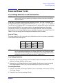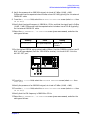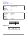
1
User’s Guide
Agilent 83220A/E DCS1800 Test Set
83220-90027
January 1998
Printed in: UK
© Copyright Agilent Technologies 1998 All Rights Reserved. Reproduction, adaptation, or
translation without prior written permission is prohibited, except as allowed under the
copyright laws.
Notices
Subject Matter
The material contained in this document is subject to change without
notice. AGILENT TECHNOLOGIES MAKES NO WARRANTY OF ANY
KIND WITH REGARD TO THIS MATERIAL, INCLUDING, BUT NOT
LIMITED TO, THE IMPLIED WARRANTIES OF MERCHANTABILITY
AND FITNESS FOR A PARTICULAR PURPOSE. Agilent Technologies
shall not be liable for errors contained herein or for incidental or
consequential damages in connection with the furnishing, performance or
use of this material.
Agilent Technologies assumes no responsibility for the use or reliability of
its software on equipment that is not furnished by Agilent Technologies.
Restricted Rights Legend
If Software is for use in the performance of a U.S. Government contract or
subcontract, Software is delivered and licensed as "Comercial computer
software" as defined in DFAR 252.227-7014 (June 1995), or as a
"commercial item" as defined in FAR 52.227-19 (June 1987) or any
equivalent agency regulation or contract clause. Use, duplication of
Software is subject to Agilent Technologies’ standard commercial license
terms, and non-DOD Department and Agencies of the U.S. Government
will receive no greater than Restricted Rights as defined in FAR
52.227-19(c)(1-2)(June 1987). U.S. Government users will receive no
greater than Limited Rights as defined in FAR 52.227-14 (June 1987) or
DFAR 252.227-7015 (b)(2) (November 1995), as applicable in any technical
data. Copyright © 200X Agilent Technologies Inc. All Rights Reserved.
Certification
Agilent Technologies certifies that this product met its published specifications at the time
of shipment from the factory. Agilent Technologies further certifies that its calibration
measurements are traceable to the United States National Bureau of Standards, to the
extent allowed by the Bureau’s calibration facility, and to the calibration facilities of other
International Standards Organization members.
Assistance
Product maintenance agreements and other customer assistance agreements are available
for Agilent Technologies products.
For any assistance, contact your nearest Agilent Technologies Sales and Service Office.
Statement of Compliance
Electromagnetic Compatibility (EMC) Information
This product has been designed to meet the protection requirements of the
European Communities Electromagnetic Compatibility (EMC) directives:
In order to preserve the EMC performance of the product, any cable which
becomes worn or damaged, must be replaced with the same type and
specification.
EN55011:1991 (Group 1, Class A)
EN50082-1:1992
- IEC 1000-4-2 (1995) ESD
- IEC 1000-4-3 (1995) Radiated Susceptibility
- IEC 1000-4-4 (1995) EFT
Safety Information
This product conforms to EN61010-1(1993) / IEC 1010-1(1990) +A1(1992)
+A2(1994) /CSA C22.2 No. 1010.1(1993) Safety requirements for Electrical
Equipment for Measurement, Control and Laboratory Use, and has been
supplied in a safe condition. The instruction documentation contains
information and warnings which must be followed by the user to ensure
safe operation and to maintain the instrument in a safe condition.
Warranty
This Agilent Technologies instrument product is warranted against defects in material
and workmanship for a period of one year from date of shipment. During the warranty
period, Agilent Technologies will, at its option, either repair or replace products which
prove to be defective.
For warranty service or repair, this product must be returned to a service facility
designated by Agilent Technologies. Buyer shall prepay shipping charges to Agilent
Technologies and Agilent Technologies shall pay shipping charges to return the product to
Buyer. However, Buyer shall pay all shipping charges, duties, and taxes for products
returned to Agilent Technologies from another country.
Agilent Technologies warrants that its software and firmware designated by Agilent
Technologies for use with an instrument will execute its programming instructions when
properly installed on that instrument. Agilent Technologies does not warrant that the
operation of the instrument, or software, or firmware will be uninterrupted or error-free.
Limitation of Warranty
The foregoing warranty shall not apply to defects resulting from improper
or inadequate maintenance by Buyer, Buyer-supplied software or
interfacing, unauthorized modification or misuse, operation outside of the
environmental specifications for the product, or improper site preparation
or maintenance.
NO OTHER WARRANTY IS EXPRESSED OR IMPLIED. AGILENT
TECHNOLOGIES SPECIFICALLY DISCLAIMS THE IMPLIED
WARRANTIES OF MERCHANTABILITY AND FITNESS FOR A
PARTICULAR PURPOSE.
Limitation of Remedies and Liability
THE REMEDIES PROVIDED HEREIN ARE BUYER'S SOLE AND
EXCLUSIVE REMEDIES. AGILENT TECHNOLOGIES SHALL NOT BE
LIABLE FOR ANY DIRECT, INDIRECT, SPECIAL, INCIDENTAL, OR
CONSEQUENTIAL DAMAGES, WHETHER BASED ON CONTRACT,
TORT, OR ANY OTHER LEGAL THEORY.
Radio Frequency Interference Statement Deutsche
Bundespost
(Federal Republic of Germany only)
Herstellerbescheinigung
Hiermit wird bescheinigt, daß dieses Gerät, System Agilent 83220A/E in
Ûbereinstimmung mit den Bestimmungen von Postverfügung 526/527
funkentstört ist.
Der Deutschen Bundespost wurde das Inverkehrbringen dieses
Gerätes/Systems angezeigt und die Berechtigung zur Ûberprüfungder
Serie auf Einhaltung der Bestimmungen eingeräumt.
Zusatzinformation für Meß- und Testgeräte:
Werden Meß - und Testgeräte mit ungeschirmten Kabeln und/oder in
offenen Meßaufbauten verwendet, so ist vom Betreiber sicherzustellen,
daß die Funk-Entstörbestimmungen unter Betriebsbedingungen an seiner
Grundstücksgrenze eingehalten werden.
Manufacturer’s Declaration
This is to certify that the equipment Agilent 83220A/E meets the radio
frequency interference requirements of Directive FTZ 526/527. The
German Bundespost has been notified that this equipment was put into
circulation and has been granted the right to check the product type for
compliance with these requirements.
Additional Information for Test and Measurement Equipment:
If test and measurement equipment is operated with unscreened cables
and/or used for measurements on open set-ups, the user has to assure that
under operating conditions the Radio Interference Limits are still met at
the border of the user’s premises.
Sound Emission
Manufacturer’s Declaration
This statement is provided to comply with the requirements of the
German Sound Emission Directive, from 18 January 1991.
This product has a sound pressure emission (at the operator position)
< 70 dB(A).
• Sound Pressure Lp < 70 dB(A).
• At Operator Position.
• Normal Operation.
• According to ISO 7779:1988/EN 27779:1991 DIN 45635 pt. 19 (Type
Test).
Herstellerbescheinigung
Diese Information steht im Zusammenhang mit den Anforderungen der
Maschinenlärminformationsverordnung vom 18 Januar 1991.
• Schalldruckpegel Lp < 70 dB(A).
• Am Arbeitsplatz.
• Normaler Betrieb.
• Nach ISO 7779:1988/EN 27779:1991 DIN 45635 pt. 19 (Typprüfung).
Responsibilities of the Customer
The customer shall provide;
1. Access to the products during the specified periods of coverage to perform maintenance.
2. Adequate working space around the products for servicing by Agilent Technologies
personnel.
3. Access to and use of all information and facilities determined necessary by Agilent
Technologies to service and/or maintain the products. (In so far as these items may
contain proprietary or classified information, the customer shall assume full
responsibility for safeguarding and protection from wrongful use.)
4. Routine operator maintenance and cleaning as specified in the Agilent Technologies
Operating and Service Manuals.
5. Consumables such as paper, disks, magnetic tapes, ribbons, inks, pens, gases, solvents,
lamps, filters, fuses, seals, etc.
General Safety Considerations
The following general safety precautions must be observed during all phases of operation,
service, and repair of this instrument. Failure to comply with these precautions or with
specific warnings elsewhere in this manual violates safety standards of design,
manufacture, and intended use of the instrument. Agilent Technologies Inc. assumes no
liability for the customer’s failure to comply with these requirements.
WARNING
This is a Safety Class I instrument (provided with a protective
earthing ground, incorporated in the power cord). The mains plug
shall only be inserted in a socket outlet provided with a protective
earth contact. Any interruption of the protective conductor inside or
outside of the instrument is likely to make the instrument
dangerous. Intentional interruption is prohibited.
DO NOT operate the product in an explosive atmosphere or in the presence of flammable
gasses or fumes.
DO NOT use repaired fuses or short-circuited fuseholders: For continued protection
against fire, replace the line fuse(s) only with fuse(s) of the same voltage and current
rating and type.
DO NOT perform procedures involving cover or shield removal unless you are qualified to
do so: Operating personnel must not remove equipment covers or shields. Procedures
involving the removal of covers and shields are for use by service-trained personnel only.
DO NOT service or adjust alone: Under certain conditions, dangerous voltages may exist
even with the equipment switched off. To avoid dangerous electrical shock, service
personnel must not attempt internal service or adjustment unless another person, capable
of rendering first aid and resuscitation, is present.
DO NOT operate damaged equipment: Whenever it is possible that the safety protection
features built into this product have been impaired, either through physical damage,
excessive moisture, or any other reason, REMOVE POWER and do not use the product
until safe operation can be verified by service-trained personnel. If necessary, return the
product to an Agilent Technologies Sales and Service Office for service and repair to
ensure the safety features are maintained.
DO NOT substitute parts or modify equipment: Because of the danger of introducing
additional hazards, do not install substitute parts or perform any unauthorized
modification to the product. Return the product to a Agilent Technologies Sales and
Service Office for service and repair to ensure the safety features are maintained.
WARNING
There are many points in the instrument which can, if contacted,
cause personal injury. Be extremely careful.
Any adjustments or service procedures that require operation of the
instrument with protective covers removed should be performed
only by trained service personnel.
Safety Symbols
The following symbols on the instrument and in the manual indicate precautions which
must be taken to maintain safe operation of the instrument
Safety Symbols
The Instruction Documentation Symbol. The product is
marked with this symbol when it is necessary for the user
to refer to the instructions in the supplied documentation.
Indicates the field wiring terminal that must be connected
to earth ground before operating the equipment - protects
against electrical shock in case of fault.
Frame or chassis ground terminal - typically connects to
the equipment's metal frame.
Alternating current (AC)
Direct current (DC)
Warning,risk of electric shock.
WARNING
CAUTION
ISM 1-A
Warning denotes a hazard. It calls attention to a
procedure, which if not correctly performed or adhered to
could result in injury or loss of life. Do not proceed beyond
a warning note until the indicated conditions are fully
understood and met.
Caution denotes a hazard. It calls attention to a
procedure, which if not correctly performed or adhered to
could result in damage to or destruction of the instrument.
Do not proceed beyond a warning note until the indicated
conditions are fully understood and met.
The CE mark shows that the product complies with all
relevant European Legal Directives.
This is a symbol of an Industrial, Scientific, and Medical
Group 1 Class A product.
The CSA mark is a registered trademark of the Canadian
Standards Association, and indicates compliance to the
standards defined by them.
Indicates that a laser is fitted. The user must refer to the
manual for specific Warning or Caution information to
avoid personal injury or damage to the product.
Contents
Agilent 83220A/E Capability . . . . . . . . . . . . . . . . . . . . . . . . . . . . . . . . . . . . . . . . . . . . . . . . . . . iii
DCS1800 Base Station . . . . . . . . . . . . . . . . . . . . . . . . . . . . . . . . . . . . . . . . . . . . . . . . . . . . . . . . iii
Where to Start . . . . . . . . . . . . . . . . . . . . . . . . . . . . . . . . . . . . . . . . . . . . . . . . . . . . . . . . . . . . . . .iv
1. Installing Your Agilent 83220A/E
Introduction . . . . . . . . . . . . . . . . . . . . . . . . . . . . . . . . . . . . . . . . . . . . . . . . . . . . . . . . . . . . . . . . . 2
Using this Chapter . . . . . . . . . . . . . . . . . . . . . . . . . . . . . . . . . . . . . . . . . . . . . . . . . . . . . . . . . . 2
Fuses and Power Cords . . . . . . . . . . . . . . . . . . . . . . . . . . . . . . . . . . . . . . . . . . . . . . . . . . . . . . . . 5
Line Voltage Selection and Fuse Selection . . . . . . . . . . . . . . . . . . . . . . . . . . . . . . . . . . . . . . . 5
Power Cords . . . . . . . . . . . . . . . . . . . . . . . . . . . . . . . . . . . . . . . . . . . . . . . . . . . . . . . . . . . . . . . 6
Operating Environment . . . . . . . . . . . . . . . . . . . . . . . . . . . . . . . . . . . . . . . . . . . . . . . . . . . . . . . 8
Rack Mounting the Agilent 83220A/E . . . . . . . . . . . . . . . . . . . . . . . . . . . . . . . . . . . . . . . . . . 8
Installation Overview . . . . . . . . . . . . . . . . . . . . . . . . . . . . . . . . . . . . . . . . . . . . . . . . . . . . . . . . . 9
Running the System Calibration Routine (Agilent 83220A only) . . . . . . . . . . . . . . . . . . . . . 11
RAM Initialization (Agilent 83220E Only) . . . . . . . . . . . . . . . . . . . . . . . . . . . . . . . . . . . . . . . . 12
DCS1800/PCS1900 Configuration . . . . . . . . . . . . . . . . . . . . . . . . . . . . . . . . . . . . . . . . . . . . . . 13
How to Return Your Agilent 83220A/E for Service . . . . . . . . . . . . . . . . . . . . . . . . . . . . . . . . . 14
General Information . . . . . . . . . . . . . . . . . . . . . . . . . . . . . . . . . . . . . . . . . . . . . . . . . . . . . . . . . 15
Operation and Storage Environment . . . . . . . . . . . . . . . . . . . . . . . . . . . . . . . . . . . . . . . . . . 15
Instrument Options . . . . . . . . . . . . . . . . . . . . . . . . . . . . . . . . . . . . . . . . . . . . . . . . . . . . . . . . 15
Specifications . . . . . . . . . . . . . . . . . . . . . . . . . . . . . . . . . . . . . . . . . . . . . . . . . . . . . . . . . . . . . 15
Lifting/Carrying the Agilent 83220A/E and HP/Agilent 8922 . . . . . . . . . . . . . . . . . . . . . . . . 16
Using both arms to lift instruments. . . . . . . . . . . . . . . . . . . . . . . . . . . . . . . . . . . . . . . . . . . . 16
2. Verifying Performance
Introduction . . . . . . . . . . . . . . . . . . . . . . . . . . . . . . . . . . . . . . . . . . . . . . . . . . . . . . . . . . . . . . . .
Setting up the Tests . . . . . . . . . . . . . . . . . . . . . . . . . . . . . . . . . . . . . . . . . . . . . . . . . . . . . . . . .
System Connection . . . . . . . . . . . . . . . . . . . . . . . . . . . . . . . . . . . . . . . . . . . . . . . . . . . . . . . . .
DCS1800 Configuration . . . . . . . . . . . . . . . . . . . . . . . . . . . . . . . . . . . . . . . . . . . . . . . . . . . . .
Preset Conditions . . . . . . . . . . . . . . . . . . . . . . . . . . . . . . . . . . . . . . . . . . . . . . . . . . . . . . . . . .
RF OUTPUT Verfication (Agilent 83220E only). . . . . . . . . . . . . . . . . . . . . . . . . . . . . . . . . . . .
RF Port Selection Verification (Agilent 83220A only) . . . . . . . . . . . . . . . . . . . . . . . . . . . . . . .
DC AM Verification for the Agilent 83220E . . . . . . . . . . . . . . . . . . . . . . . . . . . . . . . . . . . . . . .
DC AM Verification for the Agilent 83220A . . . . . . . . . . . . . . . . . . . . . . . . . . . . . . . . . . . . . . .
Phase Error & Peak Transmitter Carrier Power Verification (Agilent 83220A only) . . . . . .
Pulse Modulation Verification (Agilent 83220A only) . . . . . . . . . . . . . . . . . . . . . . . . . . . . . . .
Phase Error, Pulse Modulation & Peak Transmitter Carrier Power Verification (Agilent
83220A only) . . . . . . . . . . . . . . . . . . . . . . . . . . . . . . . . . . . . . . . . . . . . . . . . . . . . . . . . . . . . . . . .
System Specifications . . . . . . . . . . . . . . . . . . . . . . . . . . . . . . . . . . . . . . . . . . . . . . . . . . . . . . . .
Specifications vs. Characteristics . . . . . . . . . . . . . . . . . . . . . . . . . . . . . . . . . . . . . . . . . . . . .
RF Generator Specifications . . . . . . . . . . . . . . . . . . . . . . . . . . . . . . . . . . . . . . . . . . . . . . . . . . .
Frequency . . . . . . . . . . . . . . . . . . . . . . . . . . . . . . . . . . . . . . . . . . . . . . . . . . . . . . . . . . . . . . . .
Spectral Purity . . . . . . . . . . . . . . . . . . . . . . . . . . . . . . . . . . . . . . . . . . . . . . . . . . . . . . . . . . . .
Level Accuracy Over Extended Frequency Range (Agilent 83220A only) . . . . . . . . . . . . . .
0.3 GMSK Modulation . . . . . . . . . . . . . . . . . . . . . . . . . . . . . . . . . . . . . . . . . . . . . . . . . . . . . . . .
Supplemental Characteristics . . . . . . . . . . . . . . . . . . . . . . . . . . . . . . . . . . . . . . . . . . . . . . . .
Pulse Modulation . . . . . . . . . . . . . . . . . . . . . . . . . . . . . . . . . . . . . . . . . . . . . . . . . . . . . . . . . .
30 dB Pulse Modulation . . . . . . . . . . . . . . . . . . . . . . . . . . . . . . . . . . . . . . . . . . . . . . . . . . . . .
18
19
19
19
20
21
22
25
26
29
32
34
37
37
38
38
39
39
40
40
40
41
Contents-1
Contents
AM for Level Control1 . . . . . . . . . . . . . . . . . . . . . . . . . . . . . . . . . . . . . . . . . . . . . . . . . . . . . . .41
Supplemental Characteristics . . . . . . . . . . . . . . . . . . . . . . . . . . . . . . . . . . . . . . . . . . . . . . . . .41
RF Analyzer Specifications . . . . . . . . . . . . . . . . . . . . . . . . . . . . . . . . . . . . . . . . . . . . . . . . . . . .42
Frequency . . . . . . . . . . . . . . . . . . . . . . . . . . . . . . . . . . . . . . . . . . . . . . . . . . . . . . . . . . . . . . . .42
CW RF Frequency Measurement . . . . . . . . . . . . . . . . . . . . . . . . . . . . . . . . . . . . . . . . . . . . . .42
CW RF Power Measurement (RF In/Out only) . . . . . . . . . . . . . . . . . . . . . . . . . . . . . . . . . . .43
Peak Transmitter Carrier Power Measurement (RF In/Out only) . . . . . . . . . . . . . . . . . . . .43
Power Measurement Accuracy Over Extended Power range (Agilent 83220A only) . . . . . .44
Power Measurement Accuracy Over Extended Frequency Range (Agilent 83220A only) . .44
Pulse ON/OFF Ratio Measurement . . . . . . . . . . . . . . . . . . . . . . . . . . . . . . . . . . . . . . . . . . . .44
Amplitude Envelope Measurement . . . . . . . . . . . . . . . . . . . . . . . . . . . . . . . . . . . . . . . . . . . .45
Phase and Frequency Measurement . . . . . . . . . . . . . . . . . . . . . . . . . . . . . . . . . . . . . . . . . . .45
0.3 GMSK Data Recovery . . . . . . . . . . . . . . . . . . . . . . . . . . . . . . . . . . . . . . . . . . . . . . . . . . . .46
FM Demodulation Output . . . . . . . . . . . . . . . . . . . . . . . . . . . . . . . . . . . . . . . . . . . . . . . . . . . .47
Pulse Demodulation Output . . . . . . . . . . . . . . . . . . . . . . . . . . . . . . . . . . . . . . . . . . . . . . . . . .47
Output RF Spectrum Measurement . . . . . . . . . . . . . . . . . . . . . . . . . . . . . . . . . . . . . . . . . . . .48
Spectrum Analyzer Specifications . . . . . . . . . . . . . . . . . . . . . . . . . . . . . . . . . . . . . . . . . . . . . . .49
Supplemental Characteristics . . . . . . . . . . . . . . . . . . . . . . . . . . . . . . . . . . . . . . . . . . . . . . . . .49
Audio Source Specifications . . . . . . . . . . . . . . . . . . . . . . . . . . . . . . . . . . . . . . . . . . . . . . . . . . . .50
Frequency . . . . . . . . . . . . . . . . . . . . . . . . . . . . . . . . . . . . . . . . . . . . . . . . . . . . . . . . . . . . . . . .50
Output Level . . . . . . . . . . . . . . . . . . . . . . . . . . . . . . . . . . . . . . . . . . . . . . . . . . . . . . . . . . . . . .50
Audio Analyzer Specifications . . . . . . . . . . . . . . . . . . . . . . . . . . . . . . . . . . . . . . . . . . . . . . . . . .51
Frequency Measurement . . . . . . . . . . . . . . . . . . . . . . . . . . . . . . . . . . . . . . . . . . . . . . . . . . . .51
AC Voltage Measurement . . . . . . . . . . . . . . . . . . . . . . . . . . . . . . . . . . . . . . . . . . . . . . . . . . . .51
DC Voltage Measurement . . . . . . . . . . . . . . . . . . . . . . . . . . . . . . . . . . . . . . . . . . . . . . . . . . . .52
Distortion Measurement . . . . . . . . . . . . . . . . . . . . . . . . . . . . . . . . . . . . . . . . . . . . . . . . . . . . .52
Audio Filters . . . . . . . . . . . . . . . . . . . . . . . . . . . . . . . . . . . . . . . . . . . . . . . . . . . . . . . . . . . . . .52
Audio Detectors . . . . . . . . . . . . . . . . . . . . . . . . . . . . . . . . . . . . . . . . . . . . . . . . . . . . . . . . . . . .52
Oscilloscope Specifications . . . . . . . . . . . . . . . . . . . . . . . . . . . . . . . . . . . . . . . . . . . . . . . . . . . . .53
Supplemental Characteristics . . . . . . . . . . . . . . . . . . . . . . . . . . . . . . . . . . . . . . . . . . . . . . . . .53
Remote Programming . . . . . . . . . . . . . . . . . . . . . . . . . . . . . . . . . . . . . . . . . . . . . . . . . . . . . . . . .54
General Specifications . . . . . . . . . . . . . . . . . . . . . . . . . . . . . . . . . . . . . . . . . . . . . . . . . . . . . . . .55
Reference Specifications . . . . . . . . . . . . . . . . . . . . . . . . . . . . . . . . . . . . . . . . . . . . . . . . . . . . . . .56
Fixed Reference Mode . . . . . . . . . . . . . . . . . . . . . . . . . . . . . . . . . . . . . . . . . . . . . . . . . . . . . . .56
Tunable Reference Mode . . . . . . . . . . . . . . . . . . . . . . . . . . . . . . . . . . . . . . . . . . . . . . . . . . . . .56
Transit Protection . . . . . . . . . . . . . . . . . . . . . . . . . . . . . . . . . . . . . . . . . . . . . . . . . . . . . . . . . . . .57
Transit Cases . . . . . . . . . . . . . . . . . . . . . . . . . . . . . . . . . . . . . . . . . . . . . . . . . . . . . . . . . . . . . .57
Agilent Technologies Systems Engineering Assistance . . . . . . . . . . . . . . . . . . . . . . . . . . . . . .58
Ordering Information . . . . . . . . . . . . . . . . . . . . . . . . . . . . . . . . . . . . . . . . . . . . . . . . . . . . . . . . .59
Agilent 83220A/E DCS1800 Test Set . . . . . . . . . . . . . . . . . . . . . . . . . . . . . . . . . . . . . . . . . . .59
3. Screens
About This Chapter . . . . . . . . . . . . . . . . . . . . . . . . . . . . . . . . . . . . . . . . . . . . . . . . . . . . . . . . . .62
Cell Configuration . . . . . . . . . . . . . . . . . . . . . . . . . . . . . . . . . . . . . . . . . . . . . . . . . . . . . . . . . . .63
Cell Control . . . . . . . . . . . . . . . . . . . . . . . . . . . . . . . . . . . . . . . . . . . . . . . . . . . . . . . . . . . . . . . . .65
Configure . . . . . . . . . . . . . . . . . . . . . . . . . . . . . . . . . . . . . . . . . . . . . . . . . . . . . . . . . . . . . . . . . . .66
Spectrum Analyzer . . . . . . . . . . . . . . . . . . . . . . . . . . . . . . . . . . . . . . . . . . . . . . . . . . . . . . . . . . .68
Tests . . . . . . . . . . . . . . . . . . . . . . . . . . . . . . . . . . . . . . . . . . . . . . . . . . . . . . . . . . . . . . . . . . . . . .69
Entry Limit Modifications . . . . . . . . . . . . . . . . . . . . . . . . . . . . . . . . . . . . . . . . . . . . . . . . . . . . .70
Contents-2
Contents
Default Settings . . . . . . . . . . . . . . . . . . . . . . . . . . . . . . . . . . . . . . . . . . . . . . . . . . . . . . . . . . . . . 71
4. Connectors
Front-Panel Connectors . . . . . . . . . . . . . . . . . . . . . . . . . . . . . . . . . . . . . . . . . . . . . . . . . . . . . .
1. RF IN/OUT . . . . . . . . . . . . . . . . . . . . . . . . . . . . . . . . . . . . . . . . . . . . . . . . . . . . . . . . . . . . .
2. AUX RF OUT (Agilent 83220A only) . . . . . . . . . . . . . . . . . . . . . . . . . . . . . . . . . . . . . . . . .
3. AUX RF IN . . . . . . . . . . . . . . . . . . . . . . . . . . . . . . . . . . . . . . . . . . . . . . . . . . . . . . . . . . . . .
4. CONNECT TO 8922 AUX RF OUT . . . . . . . . . . . . . . . . . . . . . . . . . . . . . . . . . . . . . . . . . .
5. CONNECT TO 8922 AUX RF IN . . . . . . . . . . . . . . . . . . . . . . . . . . . . . . . . . . . . . . . . . . .
Rear Panel Connectors . . . . . . . . . . . . . . . . . . . . . . . . . . . . . . . . . . . . . . . . . . . . . . . . . . . . . . .
1. 10 MHz OUT . . . . . . . . . . . . . . . . . . . . . . . . . . . . . . . . . . . . . . . . . . . . . . . . . . . . . . . . . . .
2. 10 MHz IN . . . . . . . . . . . . . . . . . . . . . . . . . . . . . . . . . . . . . . . . . . . . . . . . . . . . . . . . . . . . .
3. AM . . . . . . . . . . . . . . . . . . . . . . . . . . . . . . . . . . . . . . . . . . . . . . . . . . . . . . . . . . . . . . . . . . . .
4. SCOPE . . . . . . . . . . . . . . . . . . . . . . . . . . . . . . . . . . . . . . . . . . . . . . . . . . . . . . . . . . . . . . . .
5. PCN INTERFACE . . . . . . . . . . . . . . . . . . . . . . . . . . . . . . . . . . . . . . . . . . . . . . . . . . . . . . .
74
74
74
75
75
75
76
76
76
77
77
77
5. GPIB
Introduction . . . . . . . . . . . . . . . . . . . . . . . . . . . . . . . . . . . . . . . . . . . . . . . . . . . . . . . . . . . . . . . .
New GPIB Commands . . . . . . . . . . . . . . . . . . . . . . . . . . . . . . . . . . . . . . . . . . . . . . . . . . . . . .
Cell Configuration Subsystem . . . . . . . . . . . . . . . . . . . . . . . . . . . . . . . . . . . . . . . . . . . . . . . . .
Configure Subsystem . . . . . . . . . . . . . . . . . . . . . . . . . . . . . . . . . . . . . . . . . . . . . . . . . . . . . . . .
Spectrum Analyzer Subsystem . . . . . . . . . . . . . . . . . . . . . . . . . . . . . . . . . . . . . . . . . . . . . . . . .
80
80
81
84
85
6. Messages
Introduction . . . . . . . . . . . . . . . . . . . . . . . . . . . . . . . . . . . . . . . . . . . . . . . . . . . . . . . . . . . . . . . . 88
Messages . . . . . . . . . . . . . . . . . . . . . . . . . . . . . . . . . . . . . . . . . . . . . . . . . . . . . . . . . . . . . . . . . 88
Contents-3
Declaration Of Conformity
Agilent Technologies
Agilent Technologies 83220A and 83220E
i
REGIONAL SALES AND SERVICE OFFICES
ASIA PACIFIC
Agilent Technologies
19/F,Cityplaza One,
1111 King’s Road,
Taikoo Shing,
Hong Kong, SAR
(tel) (852) 2599 7889
(fax) (852) 2506 9233
JAPAN
Agilent Technologies Japan Ltd
Measurement Assistance
Center
9-1, Takakura-Cho,
Hachioji-Shi, Tokyo, 192-8510
(tel) (81) 426 56 7832
(fax) (81) 426 56 7840
EUROPE
Agilent Technologies
Test & Measurement
European Marketing Org.
P.O. Box 999
1180 AZ Amstelveen
The Netherlands
(tel) (31 20) 547 9999
CANADA
Agilent Technologies
Canada Inc.
5150 Spectrum Way
Mississauga, Ontario
L4W 5G1
(tel) 1 877 894 4414
AUSTRALIA/
NEW ZEALAND
Agilent Technologies Australia
Pty Ltd
347 Burwood Highway
Forest Hill, Victoria 3131
(tel) 1-800 629 485 (Australia)
(fax) (61 3) 9272 0749
(tel) 0 800 738 378 (New Zeal’d)
UNITED STATES
Agilent Technologies
Test and Measurement Call
Center
P.O. Box 4026
Englewood, CO 80155-4026
(tel) 1 800 452 488
LATIN AMERICA
Agilent Technologies
Latin America Region Headquarters
5200 Blue Lagoon Drive,
Suite #950
Miami, Florida 33126
U.S.A.
(tel) (305) 267 4245
(fax) (305) 267 4286
ii
Agilent 83220A/E Description
Agilent 83220A/E Capability
The Agilent 83220A/E expands the capabilities of the HP/Agilent 8922 GSM Test Set
family to comprehensively test DCS1800 mobile radios across the band 1710 MHz to 1880
MHz; and PCS1900 mobile radios across the band 1850 MHz to 1990 MHz. All the features
of the RF generator, RF analyzer and general instrumentation of the HP/Agilent 8922
series are retained.
DCS1800 Base Station
The Agilent 83220A/E, when configured with the HP/Agilent 8922, can now emulate a
DCS1800/PCS1900 base station and establish and maintain a DCS1800/PCS1900 link.
Once a link has been established, comprehensive tests can be sequenced across the full
DCS1800/PCS1900 band without interrupting the link.
NOTE
PCS1900 is configured as a standard on all Agilent 83220Es with serial prefix
3524U00479 or greater. Prior to this serial break PCS1900 was available on
the Agilent 83220E as options K19.
PCS1900 is configured as a standard on all Agilent 83220As with serial prefix
3524U00424 or greater. Prior to this serial break PCS1900 was available on
the Agilent 83220A as options K19.
Your HP/Agilent 8922 must also be configured for PCS1900 operation:
HP/Agilent 8922A/B require firmware revision B.05.04 or greater.
HP/Agilent 8922E/G do not support PCS1900.
HP/Agilent 8922F require firmware revision B.05.02 or greater to support
PCS1900.
HP/Agilent 8922H require firmware revision B.06.00 or greater to support
PCS1900.
iii
How to Use This Manual
Where to Start
If you have just received the Agilent 83220A/E and want to get it ready to use for the first
time:
Thoroughly read the “Installing Your Agilent 83220A/E” chapter in this manual and follow
its instructions for:
• Unpacking the Test Set.
• Preparing it for use.
• Installation Overview.
• System Calibration.
• DCS1800/PCS1900 Configuration.
If you need to verify the unit is operating within its specifications, perform the confidence
tests in the “Verifying Performance” chapter in this manual.
Making measurements in DCS1800/PCS1900 mode is identical to making measurements
in GSM900 mode. Follow the instructions in the “Making Measurements” chapter in the
appropriate HP/Agilent 8922 Series User’s Guide to learn how to make measurements
using the DCS1800 Test System.
To find more detailed information about the Test Set, its applications, and key
descriptions, consult the “Screens”, “Connectors”, and “GPIB” chapters in this manual, and
in the appropriate HP/Agilent 8922 Series User’s Guide.
To learn how to program the Test Set, read the “GPIB” chapter in this manual, and the
“GPIB”, “Programming Examples”, and “Programmer’s Reference” chapters of the
appropriate Agilent 8922M/S Programming Reference Guide
NOTE
If you have the Agilent 83220A/E Option 010 Multi-Band Test System, refer
to the appropriate HP/Agilent 8922 Multi-Band User’s Guide for more details
on connection and operating differences.
WARNING
If this instrument is not used as specified, the protection provided by
the equipment could be impaired. This instrument must only be used
in a normal condition (in which all means of protection are intact).
iv
v
1
Installing Your Agilent 83220A/E
1
Installing Your Agilent 83220A/E
Introduction
Introduction
This section provides installation instructions for the DCS1800 Test System (Agilent
83220A/E and Agilent/HP 8922).
The Agilent 83220A/E User’s Guide covers the operation of the Agilent 83220A/E in
conjunction with an appropriate HP/Agilent 8922 Series GSM Test Set, extending the
capabilities of the HP/Agilent 8922 Series to cover the DCS1800/PCS1900 frequency
bands. The Agilent 83220A/E and HP/Agilent 8922 together constitute a
DCS1800/PCS1900 Test System.
Using this Chapter
Use the following procedure to power-up the Agilent 83220A/E, HP/Agilent 8922 DCS1800
Test System correctly. After completion of this procedure, refer to “Making Measurements”
in the appropriate HP/Agilent 8922 Series User’s Manual for an introduction to operating
the appropriate HP/Agilent 8922. Select the test required, follow the instructions as in the
appropriate HP/Agilent 8922 manual. Make the measurement.
The information contained in this guide includes:
❏ Accessories supplied.
❏ Initial inspection.
❏ Installation check list.
❏ Preparation for use.
❏ Fuses and power cords.
❏ Installation overview
❏ Running the System Calibration routine.
❏ DCS1800/PCS1900 configuration.
❏ General information.
The interface between the HP/Agilent 8922 and the Agilent 83220A/E is via a 15 way
D-Type connector and five BNC coaxial connectors.
NOTE
DCS1800 Test System setup is shown for the HP/Agilent 8922H. DCS1800
Test System setup using any of the other HP/Agilent 8922 Series will be
similar. The HP/Agilent 8922 rear panel layout is slightly different for each
model in the series.
NOTE
If you have the Agilent 83220A/E Option 010 Multi-Band Test System, refer
to the appropriate HP/Agilent 8922 Multi-Band User’s Guide for more details
on connection and operating differences.
WARNING
If this instrument is not used as specified, the protection provided by
the equipment could be impaired. This instrument must only be used
in a normal condition (in which all means of protection are intact).
2
Chapter 1
Installing Your Agilent 83220A/E
Introduction
Accessories Supplied
Table 1-1 Accessories Supplied with the DCS1800 Test System
Description
Agilent Part Number
Comments
User’s Guide
83220-90027
Interconnecting Cables
See Table 1-2
Shipped with DCS1800 Test System.
Power Cord
See Figure 1-2
Shipped with DCS1800 Test System.
Rackmount Flange Kit
5062-4071
Shipped with Option AX4
GSM/DCS1800 Mobile
Station Test Software
83212D
Available separately
1 copy shipped with Agilent 83220A/E.
Table 1-2 Supplied Cables
Type
Part Number
Model
Number
Agilent 83220A/E
HP/Agilent 8922 Port
Port
BNC
8120-1838
CONNECT TO 8922
AUX RF OUT
(Front panel)
AUX RF OUT
(Front panel)
BNC
8120-1838
CONNECT TO 8922
AUX RF IN
(Front panel)
AUX RF IN
(Front panel)
BNC
83220-61025
10 MHz IN
(Rear panel)
10 MHz OUT
(Rear panel)
BNC
83220-61025
SCOPE
(Rear panel)
SCOPE
(Rear panel)
BNC
83220-61025
AM
(Rear panel)
AM
(Rear panel)
D-type
08922-61083
PCN INTERFACE
(Rear panel)
PCN INTERFACE
(Rear panel)
CAUTION
It is advisable to connect all the cables as shown in the Installation
Overview section before switching on the DCS1800 Test System.
Initial Inspection
Inspect the shipping container for damage. If the shipping container or cushioning
material is damaged, it should be kept until the contents of the shipment have been
checked for completeness and the Agilent 83220A/E has been checked mechanically and
electrically. Procedures for checking the electrical performance of the DCS1800 Test
System are given in the “Verifying Performance” chapter of this manual. Procedures for
checking the electrical performance of the HP/Agilent 8922 are given in the “Verifying
Performance” chapter of the appropriate HP/Agilent 8922 Series User’s Guide. If the
Chapter 1
3
Installing Your Agilent 83220A/E
Introduction
contents are incomplete, if there is mechanical damage or defect, or if the DCS1800 Test
System does not pass the electrical performance tests, notify the nearest Agilent
Technologies office.
If the shipping container is damaged, or the cushioning material shows signs of stress,
notify the carrier as well as the Agilent Technologies office. Keep the shipping material for
the carrier’s inspection.
WARNING
To avoid hazardous electrical shock, do not apply power to the
Agilent 83220A/E when there are any signs of shipping damage to any
part of the Agilent 83220A/E.
If the shipping materials are in good condition, retain them for possible future use. You
may wish to ship the Agilent 83220A/E to another location or to return it to Agilent
Technologies for service. See “How to Return Your Agilent 83220A/E for Servicing,” in this
chapter.
Installation Check List
Before connecting the Agilent 83220A/E or HP/Agilent 8922 to the line (mains) voltage,
ensure the following steps are taken:
1. Read the warning in this chapter, see Preparation for Use.
2. Check that the line voltage setting on the rear panel power line modules are set to the
correct voltage, see Fuses and Power Cords.
3. Ensure that the rating of the line (mains) fuse is appropriate for the line voltage being
used, see Table 1-3 on page 6.
4. Ensure that the power cable is the correct type, see Power Cords.
Preparation for Use
WARNING
The Agilent 83220A/E and HP/Agilent 8922 Series are Safety Class 1
products (provided with a protective earth terminal). An
uninterruptible safety earth ground must be provided from the
mains power source to the product input wiring terminals, power
cord, or supplied power cord set. Whenever it is likely that the
protection has been impaired, the DCS1800 Test System must be
made inoperative and be secured against any unintended operation.
If the Agilent 83220A/E or HP/Agilent 8922 are to be energized via an
external autotransformer for voltage reduction, make sure that the
common terminal is connected to the neutral pole of the power
source.
Before connecting the Agilent 83220A/E or HP/Agilent 8922, the
protective earth terminal of the Agilent 83220A/E and HP/Agilent
8922 must be connected to the protective conductor of the (mains)
power cord. The mains plug shall only be inserted in a socket outlet
provided with a protective earth contact. The protective action must
not be negated by the use of an extension cord (power cable) without
a protective conductor (grounding). Grounding one conductor of a
two-conductor outlet is not sufficient protection.
4
Chapter 1
Installing Your Agilent 83220A/E
Fuses and Power Cords
Fuses and Power Cords
Line Voltage Selection and Fuse Selection
CAUTION
Before connecting the DCS1800 Test System to the mains (line) voltage,
ensure that the correct operating voltages and fuses have been selected for
each instrument.
A rear-panel, line power module permits operation from 100, 120, 220, or 240 Vac. The
HP/Agilent 8922 power module is documented in the Fuses and Power Cords section of
“Installing Your HP/Agilent 8922” in the appropriate HP/Agilent 8922 Series User’s guide.
On the Agilent 83220A/E, the number visible in the window (located on the module)
indicates the nominal line voltage to which the Agilent 83220A/E must be connected.
Verify that the Line Voltage Selection Cam is matched to the power source (see Figure 1-1).
Table 1-3 lists the ratings and the Agilent part numbers of the line fuses.
Internal Fuses
The fuses used within this instrument are listed below, and are non operator replaceable.
These fuses are fast blow type (F).
Fuse
NOTE
Current
Voltage
Type
F1
3.0A
250V
F
F2
6.0A
250V
F
The line voltage and line fuse ratings are selected at the factory according to
the line voltage specified when the Agilent 83220A/E and HP/Agilent 8922
were ordered. If the voltage was not specified, the line voltage and line fuse
rating are selected according to the country of destination.
Line Voltage Selection
1. Open the Cover Door by placing a small standard screwdriver between the Cover Door
and the Line Power Module, and pry open.
2. Remove the Line Voltage Selection Cam with fingers. Rotate cam so that the desired
line voltage appears at the Cover Door Window when the cam is re-inserted.
Fuse Replacement
1. Remove Fuse Holder with fingers. Replace Fuse in Fuse Holder and re-insert into the
Line Power Module.
2. Close the Cover Door by pressing it firmly.
Chapter 1
5
Installing Your Agilent 83220A/E
Fuses and Power Cords
Figure 1-1 Fuse Replacement and Line Voltage Selection
Fuse
Fuse Holder
Cover Door Window
Cover Door
Line Voltage Selection Cam
Line Power Module
WARNING
For protection against fire hazard, the line fuse should only be a
250V fuse with the correct current rating. (See Table 1-3).
Table 1-3 Line Fuse Rating and HP Part Number
Model
Line Voltage
Rating
Type
Part Number
HP/Agilent
8922
100, 120 Vac
220, 240 Vac
5.0A, 250V
2.5A, 250V
Normal blow
Normal blow
2110-0010
2110-0083
Agilent
83220A/E
100, 120 Vac
220, 240 Vac
2.0AT, 250V
1.5AT, 250V
Time delay
Time delay
2110-0303
2110-0304
Power Cords
The Agilent 83220A/E and HP/Agilent 8922 are each supplied with a three-wire power
cable. When connected to an appropriate ac power receptacle, these cables ground the
DCS1800 Test System cabinets. The type of Mains plug shipped with each instrument
depends on the country of destination. Refer to Table 1-4 on page 7 for the part numbers of
the power cables and Mains plugs available.
6
Chapter 1
Installing Your Agilent 83220A/E
Fuses and Power Cords
Table 1-4 Line Cords
PlugType
Cable Part C
Number D
Plug Description
Length,
inches
(mm)
Cable
Color
For Use In
Country
8120-1351
8120-1703
0 90/Straight BS1363Aa
4 90
90 (229) Mint Gray
90 (229) Mint Gray
United Kingdom,
Cyprus, Nigeria,
Rhodesia,
Singapore
8120-1369
8120-0696
0 Straight
NZSS198/ASC112
4
Straight/90a
79 (201) Gray
87 (221) Gray
8120-1689
8120-1692
7 Straight
90
2
79 (201) Mint Gray
79 (201) Mint Gray
8120-1378
8120-4753
8120-1521
8120-4754
80 (203) Jade Gray
90 (230) Jade Gray
80 (203)
90 (230)
Jade Gray
8120-2296
8120-3997
8120-0698
1 Straight
6 NEMA5-15Pa
Straight
1 90
90
2 Straight
3 90
3 Straight SEV 1011
1959-24507, Type 12
4 Straight/90
4 Straight/90
6 Straight/NEMA6-15P
Australia,
Argentina,
New Zealand,
Mainland China
East and West
Europe, Central
African Republic,
Arabia, Egypt
United States,
Canada, Mexico,
Philippines,
Taiwan, Japan
8120-2956
8120-2957
8120-3997
3 90/Straight
4 90/90
4 Straight/Straight
79 (201) Gray
Gray
Gray
Denmark
8120-4211
8120-4600
7 Straight IEC83-B1a
8 Straight/90
79 (201) Black
79 (201) Gray
South Africa, India
8120-1860
6 Straight CEE22-V1
(Systems Cabinet Use)
0 Straight/Straight
8 Straight/90
8 90/90
59 (150) Jade Gray
8120-1348
8120-1538
8120-2104
8120-1575
8120-2191
8120-4379
80 (203) Dark Gray
80 (203) Dark Gray
79 (201) Gray
79 (201) Gray
177 (402) Gray
90 (230) Black
Switzerland
United States,
Canada
31 (79)
Jade Gray
59 (150) Jade Gray
80 (203) Jade Gray
a. Part number shown for plug is industry identifier for plug only. Number shown
for cable is Agilent Part Number for complete cable including plug. E = Earth
Ground; L = Line; N = Neutral.
Chapter 1
7
Installing Your Agilent 83220A/E
Operating Environment
Operating Environment
Temperature: The Agilent 83220A/E may be operated in environments with temperatures
from 0 to +55°C.
Humidity: The Agilent 83220A/E may be operated in environments with humidity from 0 to
95% (non-condensing). However, protect the Agilent 83220A/E from temperature extremes
which can cause condensation within the Agilent 83220A/E.
Cooling: The Agilent 83220A/E obtains cooling airflow by forced ventilation from the fan on
its rear panel.
CAUTION
Ensure that all airflow passages at the rear and side of the Agilent 83220A/E
are clear before installing the Agilent 83220A/E. This is especially important
in a rack mount configuration.
Rack Mounting the Agilent 83220A/E
If the Agilent 83220A/E is to be rack mounted, ensure that all airflow passages at the rear
and sides of the Agilent 83220A/E are not obstructed. Full instructions for rack mounting
the Agilent 83220A/E are included with the rack mounting kit.
8
Chapter 1
Installing Your Agilent 83220A/E
Installation Overview
Installation Overview
NOTE
DCS1800 Test System setup is shown for the HP/Agilent 8922H and Agilent
83220A. DCS1800 Test System setup using any of the other HP 8922 Series
will be similar. The HP/Agilent 8922 rear panel layout is slightly different for
each model in the series.
1. Unpack the Agilent 83220A/E.
2. On the front panel, connect the Agilent 83220A/E to the HP/Agilent 8922 as shown
using the cables provided. (Part No. 8120-2682).
3. On the rear panel, connect AM to AM and SCOPE to SCOPE as shown using the cables
provided. (Part No. 83220-61025).
Chapter 1
9
Installing Your Agilent 83220A/E
Installation Overview
4. On the rear panel, connect Agilent 83220A/E 10 MHz IN to HP/Agilent 8922 10 MHz
OUT and connect the PCN INTERFACE cable as shown using the cables provided.
(Part No. 83220-61025 and 08922-61083).
5. Connect a 1, 2, 5, 10, or 13 MHz signal to HP/Agilent 8922 REF IN. If you have OPT
001, connect as shown using the cable provided. Refer to the Installation Overview
section in the “Installing Your HP/Agilent 8922” chapter of the appropriate HP/Agilent
8922 Series User’s Guide for information on configuring the reference.
6. Connect the supplied power cords to the Agilent 83220A/E and HP/Agilent 8922 and
power up the instruments.
10
Chapter 1
Installing Your Agilent 83220A/E
Running the System Calibration Routine (Agilent 83220A only)
Running the System Calibration Routine (Agilent
83220A only)
The System Calibration is a user-initiated calibration routine performed between the
HP/Agilent 8922 and the Agilent 83220A.
NOTE
The System Calibration routine should be run whenever an Agilent 83220A is
first connected to an HP/Agilent 8922, or whenever a different Agilent
83220A is connected to an HP/Agilent 8922, and after a RAM Initialize from
the SERVICE screen.
To perform a System Calibration:
1. Power down the DCS1800 Test System (Agilent 83220A and HP/Agilent 8922), achieved
by powering down the HP/Agilent 8922.
2. On the Agilent 83220A, using a short cable (<30cm) (Part No. 10502A or similar) and 2
BNC to N-type adapters (Part No. 1250-0780 or similar), link the AUX RF OUT to the
RF IN/OUT port.
3. On the HP/Agilent 8922, using a short cable (<30cm) (Part No. 10502A or similar), link
the AUDIO OUT port to the TRIGGER IN port.
4. Power up the DCS1800 Test System.
5. From the HP/Agilent 8922 front panel, select the MESSAGE Screen. SHIFT, MSSG.
6. Look for any error message.
7. There should be no error messages before starting the System Calibration Procedure, if
any errors occur, error messages are listed in the “Messages” chapter in this manual,
and in the appropriate HP/Agilent 8922 Series User’s Guide.
8. From the HP/Agilent 8922 front panel, select the TESTS Screen. TESTS
9. Using the knob, move the cursor to the Location field, and select ROM from the
Choices field.
10.Move the cursor to the Procedure field and select SYS_CAL from the Choices field.
11.Using the knob, select Run Test.
12.Follow the instructions on the screen.
13.When the System Calibration Routine has finished, Cycle the DCS1800 Test System
power.
Chapter 1
11
Installing Your Agilent 83220A/E
RAM Initialization (Agilent 83220E Only)
RAM Initialization (Agilent 83220E Only)
NOTE
A RAM Initialize from the ``SERVICE'' screen should be run whenever an
Agilent 83220E is first connected to an HP/Agilent 8922 or whenever a
different Agilent 83220E is connected to an HP/Agilent 8922.
To perform a RAM Initialize:
1. From the home screen, select the ``CONFIG'' Screen.
2. From the ``CONFIG'' Screen, select the ``SERVICE'' Screen.
3. Move the cursor next to the RAM Initialize field.
4. Select YES.
5. The instruments will then follow a restart cycle, after which, calibration information
will be down loaded, and the instruments will be ready to use.
12
Chapter 1
Installing Your Agilent 83220A/E
DCS1800/PCS1900 Configuration
DCS1800/PCS1900 Configuration
1. Access, then set up the CONFIGURE Screen with the cursor. Refer to the “Screens”
chapter in this manual and in the appropriate HP/Agilent 8922 Series User’s Guide.
2. Select the Radio Type field. From the list of choices, select either DCS1800 or PCS1900
depending on the radio type you are testing.
NOTE
When making DCS1800/PCS1900 measurements, use the RF IN/OUT port,
AUX RF OUT port or AUX RF IN port on the Agilent 83220A/E. Making
measurements in DCS1800 mode is identical to making measurements in
GSM900 mode. Follow the instructions in the “Making Measurements”
chapter in the appropriate HP/Agilent 8922 Series User’s Guide.
CAUTION
When making GSM900 measurements, disconnect the connections to the
Agilent 83220A/E and use the RF IN/OUT port, AUX RF OUT port or AUX
RF IN port on the HP/Agilent 8922. The maximum Agilent 83220A/E RF
IN/OUT port input power is 2W. Never connect a GSM900 radio to the
Agilent 83220A/E or irreparable damage may occur.
Chapter 1
13
Installing Your Agilent 83220A/E
How to Return Your Agilent 83220A/E for Service
How to Return Your Agilent 83220A/E for Service
If you need to return your Agilent 83220A/E to Hewlett-Packard, first obtain the correct
Service Center shipping address from your local sales office and carry out the following
procedure.
CAUTION
Instrument damage can result from using packaging materials other than the
original shipping materials or equivalent. Never use styrene pellets as
packaging materials. They do not adequately cushion the instrument, do not
prevent it from shifting in the carton, and can cause instrument damage due
to ESD.
1. Please send the following information with the returned instrument:
a. Type of service required.
b. Description of the problem and whether it is constant or intermittent.
c. Name and phone number of technical contact person.
d. Return address.
e. Model number of returned instrument.
f. Full serial number of returned instrument.
g. List of any accessories returned with instrument
2. Send copies of any performance data recorded for the instrument.
3. Pack the instrument in the original shipping materials or the equivalent.
4. If the original shipping materials are not available, follow these steps to repackage the
instrument for shipment:
a. Wrap the instrument in antistatic plastic to reduce the possibility of ESD-caused
damage.
b. Obtain a double-walled, corrugated cardboard carton of 159 kg (350 lb) test strength.
The carton must be large enough and strong enough to accommodate the
instrument. Allow at least 7 to 10 cms on all sides of the instrument for packing
material.
c. Surround the instrument with 7 to 10 cms of packing material to protect it and
prevent it from moving in the carton.
5. Seal the carton with strong nylon adhesive tape.
6. Mark the carton "FRAGILE, HANDLE WITH CARE."
7. Retain copies of all shipping papers.
14
Chapter 1
Installing Your Agilent 83220A/E
General Information
General Information
Operation and Storage Environment
This instrument is designed for Indoor use only.
The instrument may be operated at temperatures from 0°C to +55°C at altitudes up to
4600m (15,000 ft.). The instrument may be operated in environments up to 95% relative
humidity to 40°C, but it should be protected from temperature extremes which may cause
condensation.
CAUTION
This instrument is designed for use in Installation Category II and Pollution
Degree 2 per IEC1010 and 644 respectively.
To clean the instrument
Use a soft, clean damp cloth to clean the front-panel and side covers.
Refer to System Specifications in the “Verifying Performance” chapter in this manual
for information about the operation or storage environment.
Instrument Options
Refer to System Specifications in the “Verifying Performance” chapter in this manual
for information about instrument options.
Specifications
Refer to the “Verifying Performance” chapter in this manual for system specifications.
Chapter 1
15
Installing Your Agilent 83220A/E
Lifting/Carrying the Agilent 83220A/E and HP/Agilent 8922
Lifting/Carrying the Agilent 83220A/E and HP/Agilent
8922
To avoid potential injuries, ensure that two people are employed in lifting the HP/Agilent
8922x from it’s packaging and at all other times. Before attempting to lift or carry the
combined instruments consider the following basic lifting techniques (employing two
people) to help avoid personal injury.
Using both arms to lift instruments.
• Reach for the instruments - bend your knees and waist, and keep your back straight.
• GRASP the lowermost instrument firmly.
• LIFT with your legs.
• KEEP your shoulders level.
16
Chapter 1
2
Verifying Performance
17
Verifying Performance
Introduction
Introduction
The tests in this chapter verify the electrical performance of the DCS1800 Test System.
The basic functionality of the Agilent 83220A/E DCS1800 Test Set is checked using the
internal capabilities of the host HP/Agilent 8922. The User Confidence Test will only be
valid if the host HP/Agilent 8922 is functioning within its specification.
If any of the Confidence Tests fail verify the performance of the host HP/Agilent 8922, refer
to the Appropriate HP/Agilent 8922 Series User’s Guide and HP/Agilent 8922 Series
Assembly Level Repair manuals.
Because of the specialized nature of the DCS1800 Test System and the equipment required
to support it, it is recommended that calibration and repair be performed only by specially
equiped Agilent Technologies service centers.
A list of system specifications is found at the end of this chapter.
18
Chapter 2
Verifying Performance
Setting up the Tests
Setting up the Tests
This chapter contains the following information:
❏ System Connection
❏ Confidence Tests
• RF Output Verification (Agilent 83220E only)
• RF Port Selection Verification (Agilent 83220A only)
• DC AM Verification (HP/Agilent 8922A/B/G/H/M only)
• Phase Error and Peak Transmitter Carrier Power Verification
• Pulse Modulation Verification (HP/Agilent 8922A/B only) (Agilent 83220A only)
• Phase Error, Pulse Modulation, and Peak Transmitter Carrier Power Verification
(HP/Agilent 8922E/F/G/H/M/S only) (Agilent 83220A only)
❏ System Specifications
System Connection
Connect the Agilent 83220A/E and HP/Agilent 8922 together as shown in the
Installation Overview section of the “Installing Your Agilent 83220A/E” chapter in
this manual.
Cycle the DCS1800 Test System power.
If the message "DCS1800 Test Set has changed. Rereading cal data" is
displayed, then perform the System Calibration routine. Instructions for performing the
System Calibration routine are described in the Running the System Calibration
Routine section of the “Installing Your Agilent 83220A/E” chapter in this manual.
DCS1800 Configuration
Configure the HP/Agilent 8922 for DCS1800 operation. Refer to the DCS1800
Configuration section of the “Installing Your Agilent 83220A/E” chapter in this manual.
Chapter 2
19
Verifying Performance
Setting up the Tests
Preset Conditions
The confidence tests can be run in any order, but are shown in the preferred order of test.
Before running the confidence tests in the preferred order, it is important to cycle the
DCS1800 Test System power and then configure the HP/Agilent 8922 for DCS1800
operation.
If you wish to run the confidence tests in a different sequence, or if you wish to run one or
more of the confidence tests in isolation, it is important to start each confidence test from a
known start position each time. To achieve this, press PRESET, and then configure the
HP/Agilent 8922 for DCS1800 operation.
20
Chapter 2
Verifying Performance
RF OUTPUT Verfication (Agilent 83220E only)
RF OUTPUT Verfication (Agilent 83220E only)
This test checks transmission of RF signals from the Agilent 83220E CW Power at the
Agilent 83220E RF OUT is checked using the HP/Agilent 437B power meter and
HP/Agilent 8482A power sensor or appropriate alternatives. Signals are checked in the
frequency range 1805 MHz to 1885 MHz in 10 MHz steps.
1. Preset the HP/Agilent 8922 to a known state, (press PRESET).
2. Set the ''OPERATING MODE'' field to ''DCS1800'' and ''CW Generator''.
3. In the ''CONTROL'' section of the "CELL STATUS" screen set ''Amplitude'' to -20 dBm
and ''Frequency'' to 1805 MHz.
4. With the cursor still at the ''Frequency'' field, press the HP/Agilent 8922 INCR SET key
and enter 10 MHz.
5. Zero and calibrate the power meter. Connect the power sensor to the Agilent 83220E
RF IN/OUT port.
6. Verify that the power meter displays -20 dBm (±1.5 dB).
7. In the HP/Agilent 8922 DATA FUNCTIONS keyboard section press the up arrow key to
increment frequency in 10 MHz steps from 1805 MHz to 1885 MHz.
8. At each step verify that power meter reading is -20 dBm (±1.5 dB).
NOTE
PCS1900
The RF Output verification test should also be carried out on Agilent 83220Es
which support PCS1900. The test for PCS1900 is carried out using the same
method as for DCS1800 but with the HP/Agilent 8922 configured for
PCS1900 operation and at one frequency of 1975 MHz.
Chapter 2
21
Verifying Performance
RF Port Selection Verification (Agilent 83220A only)
RF Port Selection Verification (Agilent 83220A only)
This test checks the transmission/reception of RF signals to and from the Agilent 83220A.
CW frequency and power are checked using the HP/Agilent 8922 spectrum analyzer (On
an HP/Agilent 8922E/F/H, the spectrum analyzer is only available with Option 006 fitted)
and CW/AF analyzer (Power measurements are not available from the AUX RF IN port.
On the CW MEAS/AF ANALYZER screen, CW power will read “− − − −”).
1. Preset the HP/Agilent 8922 to a known state, (press PRESET), then configure the
HP/Agilent 8922 for DCS1800 operation.
2. Select the RF GENERATOR / RF ANALYZER screen (press SHIFT 1 RFG/RFA), and alter the
settings as follows:
Heading
Field
Setting
RF Gen
RF Output Amplitude
AUX RFOUT - 5.0 dBm
Mod Source
GMSK
Off
RF Analyzer
Frequency Amplitude
1806 MHz - 5.0 dBm
3. Remove any connections to the Agilent 83220A RF IN/OUT port.
4. From the To Screen field, select the CW MEAS/AF ANALYZER screen (select More then
CW AF ANL).
5. Zero the power meter by selecting ZeroPower from the Meas Cntrl field.
6. On the Agilent 83220A, using a short cable (<30cm - Part No. 10502A or similar) and 2
BNC to N-type adapters (Part No. 1250-0780 or similar), link the AUX RF OUT to the
RF IN/OUT port.
7. From the To Screen field, select the SPECTRUM ANALYZER screen (select More then
SPEC ANL).
1.
To select the RF GENERATOR/RF ANALYZER screen on an HP/Agilent 8922A/B, simply press
RFG/RFA.
22
Chapter 2
Verifying Performance
RF Port Selection Verification (Agilent 83220A only)
8. Verify the presence of an 1806 MHz signal, at a level of 5 dBm (+3 dB, −4 dB).
Differences from the expected value includes a loss of 0.5 dB (typically) for the external
10502A RF cable.
9. From the To Screen field, select the CW MEAS/AF ANALYZER screen (select More then
CW AF ANL).
10.Verify that the signal frequency is 1806 MHz ±32 Hz, and that the signal level is 5 dBm
(+1 dB, −2 dB). Differences from the expected value includes a loss of 0.5 dB (typically)
for the external 10502A RF cable.
11.Select the RF GENERATOR / RF ANALYZER screen (press SHIFT RFG/RFA), and alter the
settings as follows:
Heading
RF Analyzer
Field
RF Input Amplitude
Setting
AUX RF IN
5.0 dBm
12.On the Agilent 83220A, using a short cable (<30cm - Part No. 10502A or similar) and 2
BNC to N-type adapters (Part No. 1250-0780 or similar), link the AUX RF IN to the
AUX RF OUT port.
13.From the To Screen field, select the SPECTRUM ANALYZER screen (select More then
SPEC ANL).
14.Verify the presence of an 1806 MHz signal, at a level of 5 dBm (+3 dB, −4 dB).
15.From the To Screen field, select the CW MEAS/AF ANALYZER screen (select More then
CW AF ANL).
16.Verify that the CW frequency is 1806 MHz ±32 Hz.
17.Select the RF GENERATOR / RF ANALYZER screen (press SHIFT RFG/RFA), and alter the
settings as follows:
Chapter 2
23
Verifying Performance
RF Port Selection Verification (Agilent 83220A only)
Heading
Field
Setting
RF Gen
RF Output Amplitude
RF IN/OUT
−20.0 dBm
RF Analyzer
Amplitude
−20.0 dBm
18.On the Agilent 83220A, using a short cable (<30cm - Part No. 10502A or similar) and 2
BNC to N-type adapters (Part No. 1250-0780 or similar), link the AUX RF IN to the RF
IN/OUT port.
19.From the To Screen field, select the SPECTRUM ANALYZER screen (select More then
SPEC ANL).
20.Verify the presence of an 1806 MHz signal, at a level of −20 dBm (+3 dB, −4 dB).
21.From the To Screen field, select the CW MEAS/AF ANALYZER screen (select More then
CW AF ANL).
22.Verify that the CW frequency is 1806 MHz ±32 Hz.
24
Chapter 2
Verifying Performance
DC AM Verification for the Agilent 83220E
DC AM Verification for the Agilent 83220E
NOTE
Applicaable to the HP/Agilent 8922A/B/G/H/M only. DC AM is not available
on an HP/Agilent 8922E/F.
This test checks transmission of the DC AM control voltage from the HP/Agilent 8922 to
the Agilent 83220E. The resulting change in CW Power is checked using the
HP/Agilent 8922 CW/AF analyzer and spectrum analyzer.
1. Preset the HP/Agilent 8922 to a known state, (press PRESET), then configure the
HP/Agilent 8922 for DCS1800 operation.
2. Set the OPERATING MODE field to DCS1800 and CW Generator.
3. Zero the power meter (page 21 for power meter details)and connect the power meter
sensor to the Agilent 83220E RF IN/OUT port.
4. In the CONTROL section of the CELL STATUS screen, set Amplitudes to -30 dBm and
Frequency to 1805 MHz.
5. Verify the power meter displays -30 dBm (±1.5 dB).
6. In the measurements section, select AUDIO and set the fields as follows;
Field
Setting
Frequency
0 Hz
Amplitude
1V
Coupling
DC
7. Select the RF GENERATOR / RF ANALYZER screen (press SHIFT RFG/RFA), and set the
Mod Source DC AM field to Ext.
8. Connect a BNC cable from the HP/Agilent 8922 AUDIO OUT to AM/IN SPEECH:
9. Verify that the power meter reading has increased by 6 dB to -24 dBm (±1.5 dB).
Chapter 2
25
Verifying Performance
DC AM Verification for the Agilent 83220A
DC AM Verification for the Agilent 83220A
NOTE
Applicaable to the HP/Agilent 8922A/B/G/H/M only. DC AM is not available
on an HP/Agilent 8922E/F.
This test checks transmission of the DC AM control voltage from the HP/Agilent 8922 to
the Agilent 83220A. The resulting change in CW Power is checked using the
HP/Agilent 8922 CW/AF analyzer and spectrum analyzer.
1. Preset the HP/Agilent 8922 to a known state, (press PRESET), then configure the
HP/Agilent 8922 for DCS1800 operation.
2. Select the RF GENERATOR / RF ANALYZER screen (press SHIFT RFG/RFA), and set as
follows:
Heading
Field
Setting
RF Gen
RF Output Amplitude
AUX RFOUT, 0.0 dBm
Mod Source
GMSK
Off
AF Gen
Frequency Amplitude
Coupling
0.0 Hz, 1.0 V AC/DC
RF Analyzer
Frequency Amplitude
1806 MHz, 0.0 dBm
3. Remove any connections to the Agilent 83220A RF IN/OUT port.
4. From the To Screen field, select the CW MEAS/AF ANALYZER screen (select More then
CW AF ANL).
5. Zero the power meter by selecting ZeroPower from the Meas Cntrl field.
6. On the Agilent 83220A, using a short cable (<30cm - Part No. 10502A or similar) and 2
BNC to N-type adapters (Part No. 1250-0780 or similar), link the AUX RF OUT to the
RF IN/OUT port.
7. Verify that the CW power measures 0 dBm (+1 dB, −2 dB).
26
Chapter 2
Verifying Performance
DC AM Verification for the Agilent 83220A
8. Select the RF GENERATOR / RF ANALYZER screen (press SHIFT RFG/RFA), and alter the
settings as follows:
Heading
Mod Source
Field
DC AM
Setting
Ext
9. On the HP/Agilent 8922, using a short cable (<30cm - Part No. 10502A or similar), link
the AUDIO OUT port in the AUDIO section to the IN AM/SPEECH port in the
MODULATION section.
10.From the To Screen field, select the CW MEAS/AF ANALYZER screen (select More then
CW AF ANL).
11.Verify that the CW power has increased by approximately 6 dB.
12.Select the RF GENERATOR / RF ANALYZER screen (press SHIFT RFG/RFA), and alter the
settings as follows:
Heading
AF Gen
Field
Frequency Amplitude
Setting
0.1 Hz, 0.707 V
13.From the To Screen field, select the CW MEAS/AF ANALYZER screen (select More then
CW AF ANL).
14.Verify that the CW power varies between 6 dBm (+1 dB, −2 dB) and −25 dBm (or lower).
Differences from the expected value includes a loss of 0.5 dB (typically) for the external
10502A RF cable.
15.From the To Screen field, select the SPECTRUM ANALYZER screen (select More then
SPEC ANL).
16.Alter the SPECTRUM ANALYZER screen as follows:
Chapter 2
27
Verifying Performance
DC AM Verification for the Agilent 83220A
Field
Ref Level
Setting
7.0 dBm
17.Verify that the CW power varies between 6 dBm (+3 dB, −4 dB) and −60 dBm (or lower).
18.Remove the cable from the AUDIO OUT and IN AM/SPEECH ports.
28
Chapter 2
Verifying Performance
Phase Error & Peak Transmitter Carrier Power Verification (Agilent 83220A only)
Phase Error & Peak Transmitter Carrier Power
Verification (Agilent 83220A only)
This test checks the phase stability of the Agilent 83220A, and operation of the
Agilent 83220A Peak TX Power Meter.
1. Preset the HP/Agilent 8922 to a known state, (press PRESET), then configure the
HP/Agilent 8922 for DCS1800 operation.
2. Select the RF GENERATOR / RF ANALYZER screen (press RFG/RFA), and set as follows:
Heading
Field
Setting
RF Gen
RF Output Amplitude Frequency
AUX RFOUT
5.0 dBm
1806 MHz
AF Gen
Frequency Amplitude Coupling
100 Hz
5.0 V AC/DC
RF Analyzer
RF Input Frequency Amplitude
RF IN/OUT
1806 MHz
5.0 dBm
3. Select the MEASUREMENT SYNC screen (press MEAS ARM), and alter the settings as
follows:
Heading
Meas Trig
Field
Trig Source
Setting
Ext Meas
4. On the Agilent 83220A, using a short cable (<30cm - Part No. 10502A or similar) and 2
BNC to N-type adapters (Part No. 1250-0780 or similar), link the AUX RF OUT to the
RF IN/OUT port.
Chapter 2
29
Verifying Performance
Phase Error & Peak Transmitter Carrier Power Verification (Agilent 83220A only)
5. On the HP/Agilent 8922, using a short cable (<30cm - Part No. 10502A or similar), link
the AUDIO OUT port in the AUDIO section to the TRIGGER IN port in the MEASURE
section.
6. From the To Screen field, select the DSP ANALYZER screen, (DSP ANL), and alter the
settings as follows:
Heading
Field
DSP Analyzer
Setting
View
PhaseMain
7. Press MEAS ARM.
8. Verify the following:
Measurement
Result
RMS Phase Error
< 1.00°
Peak Phase Error
< 4.00°
Frequency Error
< ±32 Hz
9. Alter the DSP ANALYZER screen as follows:
Heading
DSP Analyzer
Field
View
Setting
Ampl Main
10.Remove the connection to the Agilent 83220A RF IN/OUT port.
11.Zero the power meter by selecting ZeroPower from the View field.
12.Reconnect the connection to the Agilent 83220A RF IN/OUT port.
30
Chapter 2
Verifying Performance
Phase Error & Peak Transmitter Carrier Power Verification (Agilent 83220A only)
13.Verify that the Peak Transmitter Power measures 5.0 dBm (+1 dB, −2 dB). Differences
from expected values should be mainly due to losses in the external RF cables. Check
that the reading is consistent with the cable being used. (10502A has approx 0.5 dB
loss).
14.Remove the cable from the AUDIO OUT and TRIGGER IN ports.
NOTE
PCS1900
The Phase Error and Peak Transmitter Carrier Power Verification test
should also be carried out on Agilent 83220As which support PCS1900. The
test for PCS1900 is carried out using the same method as for DCS1800 but
with the HP/Agilent 8922 configured for PCS1900 operation and in step 2, an
RF Generator and RF Analyzer frequency of 1975 MHz should be selected.
Chapter 2
31
Verifying Performance
Pulse Modulation Verification (Agilent 83220A only)
Pulse Modulation Verification (Agilent 83220A only)
NOTE
Applicable to the HP/Agilent 8922A/B only.
This test checks the operation of the Agilent 83220A pulse modulator using the
HP/Agilent 8922A/B spectrum analyzer.
1. Preset the HP/Agilent 8922 to a known state, (press PRESET), then configure the
HP/Agilent 8922 for DCS1800 operation.
2. Select the RF GENERATOR / RF ANALYZER screen (press RFG/RFA), and set as follows:
Heading
Field
Setting
RF Gen
RF Output Amplitude
AUX RFOUT
5.0 dBm
Mod Source
GMSK Pulse
Off
Ext, Normal
AF Gen
Frequency Amplitude Coupling
0.5 Hz
5.0 V
AC/DC
RF Analyzer
Frequency Amplitude
1806 MHz
5.0 dBm
3. Remove any connections to the Agilent 83220A RF IN/OUT port.
4. From the To Screen field, select the CW MEAS/AF ANALYZER screen (select More then
CW AF ANL).
5. Zero the power meter by selecting ZeroPower from the Meas Cntrl field.
6. On the Agilent 83220A, using a short cable (<30cm - Part No. 10502A or similar) and 2
BNC to N-type adapters (Part No. 1250-0780 or similar), link the AUX RF OUT to the
RF IN/OUT port.
32
Chapter 2
Verifying Performance
Pulse Modulation Verification (Agilent 83220A only)
7. On the HP/Agilent 8922, using a short cable (<30cm - Part No. 10502A or similar), link
the AUDIO OUT port in the AUDIO section to the PULSE port in the MODULATION
section.
8. From the To Screen field, select the SPECTRUM ANALYZER screen (select More then
SPEC ANL).
9. Verify the CW power alternates between 5 dBm (+3 dB, −4 dB) and −70 dBm (or lower).
Differences from expected values should be mainly due to losses in the external RF
cables. Check that the reading is consistent with the cable being used. (10502A has
approx 0.5 dB loss)
10.Remove the cable from the AUDIO OUT and PULSE ports.
Chapter 2
33
Verifying Performance
Phase Error, Pulse Modulation & Peak Transmitter Carrier Power Verification (Agilent 83220A only)
Phase Error, Pulse Modulation & Peak Transmitter
Carrier Power Verification (Agilent 83220A only)
NOTE
Applicable to the HP/Agilent 8922E/F/G/H/M/S only.
This test checks the phase stability of the Agilent 83220A, and operation of the
Agilent 83220A pulse modulator and Peak Tx Power Meter.
1. Cycle the DCS1800 Test System power.
2. Select the TESTS screen (press TESTS).
3. Using the knob, move the cursor to the Location field, and select ROM from the
Choices field.
4. If you are using an HP/Agilent 8922E, move the cursor to the Procedure field, and
select EDCSDIAG from the Choices field.
5. If you are using an HP/Agilent 8922G, move the cursor to the Procedure field, and
select GDCSDIAG from the Choices field.
6. Select Run Test, or press L1.
7. Follow the instruction given on the HP/Agilent 8922E/G screen. (Ignore all pass/fail
results shown on the screen while the program is running.)
8. Once the program has finished, select the RF GENERATOR / RF ANALYZER screen
(press SHIFT RFG/RFA), and set as follows:
Heading
Field
Setting
RF GEN
Amplitude
5.0 dBm
RF Analyzer
Amplitude
5.0 dBm
9. Ensure that the Agilent 83220A AUX RF OUT port is connected to the
HP/Agilent 83220A RF IN/OUT port, using a short cable (<30cm - Part No. 10502A or
similar) and 2 BNC to N-type adapters (Part No. 1250-0780 or similar).
34
Chapter 2
Verifying Performance
Phase Error, Pulse Modulation & Peak Transmitter Carrier Power Verification (Agilent 83220A only)
10.From the To Screen field, select the DSP ANALYZER screen, (DSP ANL), and alter the
settings as follows:
Heading
Field
DSP Analyzer
Setting
View
PhaseMain
11.Press MEAS ARM.
12.Verify the following:
Measurement
Result
RMS Phase Error
< 1.00°
Peak Phase Error
< 4.00°
Frequency Error
< ±32 Hz
13.Remove the connection to the Agilent 83220A RF IN/OUT port.
14.Alter the DSP ANALYZER screen as follows:
Heading
DSP Analyzer
Field
View
Setting
Ampl Main
15.Zero the power meter by selecting ZeroPower from the View field.
16.Reconnect the connection to the Agilent 83220A RF IN/OUT port.
17.Alter the DSP ANALYZER screen as follows:
Heading
DSP Analyzer
Field
View
Setting
Ampl Rise
18.Verify that the Peak Transmitter Power measures 5.0 dBm (+1 dB, −2 dB). Differences
from expected values should be mainly due to losses in the external RF cables. Check
that the reading is consistent with the cable being used. (10502A has approx 0.5 dB
loss).
19.Verify the presence of a rising pulse, within the limits of the amplitude mask, on the
DSP Analyzer screen.
20.Alter the DSP ANALYZER screen as follows:
Chapter 2
35
Verifying Performance
Phase Error, Pulse Modulation & Peak Transmitter Carrier Power Verification (Agilent 83220A only)
Heading
DSP Analyzer
Field
View
Setting
Ampl Fall
21.Verify the presence of a falling pulse, within the limits of the amplitude mask, on the
DSP Analyzer screen.
22.Cycle the DCS1800 Test System power.
36
Chapter 2
Verifying Performance
System Specifications
System Specifications
This section contains the system specifications and supplemental characteristics that
apply to the Agilent 83220A/E DCS1800 Test Set when used in conjunction with any of the
HP/Agilent 8922 Series.
Specifications vs. Characteristics
Specifications
Specifications describe the instrument’s warranted performance and apply after a 30
minute warm-up over the temperature range 0 to 55°C unless otherwise stated.
Supplemental Characteristics
(Shown in italics) are intended to provide additional information, useful in applying the
instrument by giving typical (expected), but not warranted performance parameters.
These characteristics are shown in italics or labeled as “typical”, “usable to”, or “nominal”.
NOTE
Chapter 2
If you have the Agilent 83220A/E Option 010 Multi-Band Test System, refer
to the appropriate HP/Agilent 8922 Multi-Band User’s Guide for more details
on system specification differences.
37
Verifying Performance
RF Generator Specifications
RF Generator Specifications
Frequency
Range:
1710 MHz to 1785 MHz, 1805 MHz to 1990 MHz.
Resolution:
1 Hz.
Accuracy:
Reference Accuracy ±0.5 Hz.
Stability:
Same as Reference.
Supplemental Charateristics
Frequency
Underrange:
Will underrange to 1700 MHz with uncalibrated output and modulation.
Switching Speed:
577 µs in hop mode (refer to 0.3 GMSK modulation specifications).
RF In/Out Connector
Level Range:
−19 to −127 dBm.
(For >1880 MHz, -19 to -127 dBm.)
Level Resolution:
0.1 dB.
Level Accuracy:a
±1.0 dB, levels ≥−127 dBm
(For >1880 MHz, ±1.0 dB, levels ≥−127 dBm.)
±1.0 dB, typically for levels ≥−127 dBm while hopping.b
Reverse Power:
2 watts continuous.
SWR:
<1.5:1. (For >1880 MHz, <1.5:1.)
a. When using 30 dB pulse modulation, level accuracy is typically ±2 dB.
Level accuracy is typically ±1.5 dB with the HP/Agilent 8922 series.
b. Level accuracy degrades 0.2 dB when using the RF IN/OUT connector for both
RF generator and RF analyzer.
38
Chapter 2
Verifying Performance
RF Generator Specifications
Aux RF Out Connector (Agilent 83220A only)
Level Range:
+7 to −127 dBm. (For >1880 MHz, +7 dBm.)
Level Resolution:
0.1 dB.
Level Accuracya:
±1.0 dB, levels ≥−127 dBm.(For >1880 MHz, ±1.0 dB, levels ≥−127 dBm.)
±1.0 dB, typically for levels ≥−127 dBm while hopping.
Reverse Power:
200 milliwatts.
SWR:
2.0:1, <−4 dBm. (For >1880 MHz, 2.0:1, <−4 dBm.)
a. When using 30 dB pulse modulation, level accuracy is typically ±2 dB.
Level accuracy is typically ±1.5 dB with the HP/Agilent 8922 Series.
Spectral Purity
Spurious Signals
(for ≤1 dBm output level at AUX RF OUT or ≤25 dBm output
level at RF IN/OUT).
Harmonics:
<−25 dBc.
Non-Harmonic Spurious:
<−50 dBc, >5 kHz offset from carrier.
Level Accuracy Over Extended Frequency Range (Agilent
83220A only)
Measurements taken at −127 dBm.
Chapter 2
39
Verifying Performance
0.3 GMSK Modulation
0.3 GMSK Modulation
After one timeslot, 577 µs, from an isolated RF generator hop trigger.
Phase Error:
≤1° rms.
Peak Phase Error:
≤4° peak.
Frequency Error:
±(0.01 ppm (22 Hz) + reference accuracy) for normal bursts.
Typically ±(0.02 ppm (32 Hz) + reference accuracy), for RACHs.
Amplitude Flatness:
±0.25 dB peak.
Clock Input
Frequency:
270.833 kHz ±2 Hz (relative to reference).
Level:
TTL.
Data Inputa
Format:
Non differentially encoded input.
Level:
TTL.
a. Not available with HP/Agilent 8922E.
Supplemental Characteristics
After three timeslots, 1.73 ms, from an isolated RF generator hop trigger.
Phase Error:
≤0.5° rms.
Peak Phase Error:
≤2.0° peak.
Frequency Error:
±(0.005 ppm (9 Hz) + reference accuracy), for normal bursts.
±(0.01 ppm (18 Hz) + reference accuracy), for RACH bursts.
Pulse Modulation
Input Levels:
TTL.
Rise/Fall Time
(10 - 90%):
≤5 µs.
Supplemental Characteristics
On/Off Ratio:
40
>80 dB.
Chapter 2
Verifying Performance
0.3 GMSK Modulation
30 dB Pulse Modulation 1
Supplemental Characteristics
All timeslots 30 dB higher than desired/active timeslot to test adjacent timeslot rejection.
Input Levels:
TTL.
Rise/Fall Time (10 - 90%):
≤5 µs.
AM for Level Control1
For output levels ≤+1 dBm at AUX RF OUT (Agilent 83220A only) or ≤−25 dBm atRF
IN/OUT.
Supplemental Characteristics
Input
Range:
−1.0 V to +0.6 V.
Impedance:
600 Ω nominal, DC coupled.
Sensitivity:
100% AM per volt, nominal.
Calibration:
0 VDC input produces calibrated output from the RF generator.
Rise/Fall Time (10 - 90%):
<20 µs.
1.
Not available with HP 8922E.
Chapter 2
41
Verifying Performance
RF Analyzer Specifications
RF Analyzer Specifications
Frequency
Range:
1710 MHz to 1900 MHz, 1910 MHz to 1990 MHz.
Resolution:
1 Hz.
Hop Mode Resolution:
100 kHz.
Offset Frequency:
≤50 kHz.
Offset Resolution:
1 Hz for digital data recovery and modulation accuracy
measurements.
RF In/Out SWR:
<1.5:1.
Supplemental Characteristics
Frequency Overrange:
1700 MHz to 1710 MHz and 1900 MHz to 1910 MHz with
unspecified performance.
Offset Resolution:
500 Hz for FM demodulation out.
CW RF Frequency Measurement
Range:
1710 MHz to 1900 MHz, 1910 MHz to 1990 MHz.
Level Range
RF In/Out:
−13 to +32 dBm.
Aux RF IN:
−23 to +20 dBm.
Input Frequency Setting
Errora:
500 kHz.
Accuracy:
±(1 Hz + reference accuracy).
a. When setting up the RF analyzer for measurements, you enter the expected frequency and level for the incoming signal. If the frequency is within the limits
shown the specified performance will result.
Supplemental Characteristics
Minimum Resolution:
1 Hz.
Frequency Overrange:
1700 MHz to 1710 MHz and 1900 MHz to 1910 MHz with
unspecified performance.
42
Chapter 2
Verifying Performance
RF Analyzer Specifications
CW RF Power Measurement (RF In/Out only)
Range:
−5 to +32 dBm.
Input Frequency Setting
Error:
±500 kHz.
Accuracya:
±0.5 dB ± noise effects (0.015 mW),(over the range 1710 MHz to
1880 MHz and 0 dBm to +32 dBm).
(For >1880 MHz, ±0.5 dB ± noise effects (0.015 mW)).
(For <0 dBm, ±0.5 dB ± noise effects (0.015 mW)).
a. To calculate accuracy, add or subtract the 0.5 dB error (0.6 dB for Peak Transmitter Carrier Power) from the absolute power in dBm then convert to mW and
add or subtract the 0.015 mW noise effect.
Supplemental Characteristics
Minimum Resolution:
0.01 dB.
Peak Transmitter Carrier Power Measurement (RF In/Out
only)
After one timeslot 577 µs, from an isolated receiver hop trigger.
Range:
-5 to +32 dBm.
Input Frequency Setting
Errora:
±10 kHz.
Input Level Setting Errora:
±3 dB.
Accuracyb:
±0.6 dB ± noise effects (0.015 mW), (over the range 1710 MHz to
1880 MHz and 0 dBm to +32 dBm).
(For >1880 MHz, ±0.6 dB ± noise effects (0.015 mW)).
(For <0 dBm, ±0.6 dB ± noise effects (0.015 mW)).
a. When setting up the RF analyzer for measurements, you enter the expected frequency and level for the incoming signal. If the frequency is within the limits
shown the specified performance will result.
b. To calculate accuracy, add or subtract the 0.5 dB error (0.6 dB for Peak Transmitter Carrier Power) from the absolute power in dBm then convert to mW and
add or subtract the 0.015 mW noise effect.
Supplemental Characteristics
Minimum Resolution:
Chapter 2
0.2 dB.
43
Verifying Performance
RF Analyzer Specifications
Power Measurement Accuracy Over Extended Power range
(Agilent 83220A only)
Measurements taken at 1880 MHz.
Power Measurement Accuracy Over Extended Frequency
Range (Agilent 83220A only)
Measurements taken at 0 dBm.
Pulse ON/OFF Ratio Measurement 1
ON power is averaged over the useful part of the burst. OFF power is averagedover a 1 bit
interval centered at a user specified time. Non-hopped mode only.
1.
44
On an HP/Agilent 8922E/F/H, Pulse ON/OFF Ratio Measurement is only available withOption
006.
Chapter 2
Verifying Performance
RF Analyzer Specifications
Input Frequency Setting
Errora:
±10 kHz.
Input Level Setting Errora:
±3 dB.
Timing Accuracy:
±1.7 µs (±1.1 µs typical).
a. When setting up the RF analyzer for measurements, you enter the expected frequency and level for the incoming signal. If the frequency is within thelimits
shown the specified performance will result.
Accuracy (ON/OFF ≥40 dB, RF In/Out only)
OFF Power (dBm)
ON/OFF Ratio Accuracy
−48 to −19
±2.4 dB
±1.1 dB typically
−55 to −48
±2.9 dB
±1.3 dB typically
Amplitude Envelope Measurement
After one timeslot, 577 µs, from an isolated receiver hop trigger.
Measurement Range
RF In/Out:
−13 to +32 dBm.
Aux RF In:(Agilent
83220A only)
−23 to +20 dBm.
Input Frequency Setting
Error:
±10 kHz.
Inaccuracy due to Noise:
Relative
Level
Input Level Setting Error
±1 dB
±3 dB
±3 dB w/5 averages
0 dB
<±0.15 dB pk
<±0.2 dB pk
<±0.2 dB pk
−6 dB
<±0.2 dB pk
<±0.3 dB pk
<±0.3 dB pk
−30 dB
<+ 3.0 dB
−3.8 dB
<+4.2 dB
-7.5 dB
< +2.2 dB
-2.6 dB
Phase and Frequency Measurement
(As described in GSM recommendation 11.10)
After one timeslot, 577 µs, from an isolated receiver hop trigger.
Chapter 2
45
Verifying Performance
RF Analyzer Specifications
Range
RF In/Out:
−13 to +32 dBm.
Aux RF In:(Agilent 83220A
only)
−23 to +20 dBm.
Input Frequency Setting
Error:a
±10 kHz.
Input Level Setting Error:
±3 dB.
RMS Phase Error Accuracy:
≤1° rms.
Peak Phase Error Accuracy:
≤4° peak.
Frequency Error Accuracy:
±(0.01 ppm (22 Hz) + reference accuracy),for normal bursts.
Typically, ±(0.02 ppm (32 Hz) + reference accuracy), for RACHs.
a. When setting up the RF analyzer for measurements, you enter the expected frequency and level for the incoming signal. If the frequency is within the limits
shown the specified performance will result.
Supplemental Characteristics
After three timeslots, 1.73 ms, from an isolated receiver hop trigger.
RMS Phase Error Accuracy:
≤0.5° rms.
Peak Phase Error Accuracy:
≤2° peak.
Frequency Error Accuracy:
±(0.005 ppm (9 Hz) + reference accuracy), for normal bursts.
±(0.01 ppm (18 Hz) + reference accuracy), for RACH bursts.
0.3 GMSK Data Recovery
After one timeslot, 577 µs, from an isolated receiver hop trigger.
Range
RF In/Out:
−13 to +32 dBm.
Aux RF In:(Agilent 83220A
only)
−23 to +20 dBm.
Input Frequency Setting
Error:a
±100 Hz.
Required Phase Input
Accuracy:
≤5˚ rms, ≤ 20˚ peak.
Demodulation Duty Cycle:
1 timeslot per frame.
Outputs:
Data, Clock and Data Valid
Data Output Clock:
Clocked at 1 MHz rate.
Delay, data:
≤1 frame (4.62 ms)
Output Level:
TTL.
46
Chapter 2
Verifying Performance
RF Analyzer Specifications
a. When setting up the RF analyzer for measurements, you enter the expectedfrequency and level for the incoming signal. If the frequency is within thelimits
shown the specified performance will result.
FM Demodulation Output
Range
RF IN/OUT:
−13 to +32 dBm.
AUX RF IN:(Agilent
83220A only)
−23 to +20 dBm.
Sensitivity:
20 µV/Hz ±5% (into an open circuit).
Input Frequency Setting
Error:
±50 kHz, with ≤100 kHz pk deviation.
Input Level Setting Error:
±3 dB.
Supplemental Characteristics
3 dB Bandwidth:
DC to 270 kHz.
Ue
600 Ω.
DC Offset:
≤5 mV.
Pulse Demodulation Output
Range
RF In/Out:
−13 to +32 dBm.
Aux RF In:(Agilent 83220A
only)
−23 to +20 dBm.
Input Frequency Setting
Errora:
±50 kHz.
Input Level Setting Error:
±3 dB.
Rise time (10 - 90%):
≤2.5 µs.
Fall time (90 - 10%):
≤2.5 µs.
a. When setting up the RF analyzer for measurements, you enter the expected frequency and level for the incoming signal. If the frequency is within the limits
shown the specified performance will result.
Supplemental Characteristics
Output Impedance:
600 Ω, DC coupled.
Output Level:
2 Vpk into an open circuit.
Chapter 2
47
Verifying Performance
RF Analyzer Specifications
Output RF Spectrum Measurement 1
After one timeslot, 577 µs, from an isolated receiver hop trigger.
(When using “Output RF Spectrum due to Ramping” measurement, the dynamic range is
decreased by 12 dB (due to Peak Hold)).
Range
RF In/Out:
−13 to +32 dBm.
Aux RF IN:(Agilent 83220A
only)
−23 to +20 dBm.
Input Levels for Optimum
Dynamic Range
RF In/Out:
−3, +2, +7, +12, +17, +22, +27, +32 dBm.
Aux RF IN:(Agilent 83220A
only)
−13, −8, −3, +2, +7, +12, +17,+22 dBm.
Input Frequency Setting
Errora:
±10 kHz.
Input Level Setting Error:
±3 dB.
a. When setting up the RF analyzer for measurements, you enter the expected frequency and level for the incoming signal. If the frequency is within the limits
shown the specified performance will result.
Supplemental Characteristics
Log Linearity:
±0.4 dB.
Amplitude Flatness:
±1.0 dB.
Amplitude Resolution:
0.4 dB.
Dynamic Range (dB):
This describes the spectrum analyzer resolution bandwidth filter
used when measuring output RF spectrum. The dynamic range
of the measurement will be a combination of this filter response
and the modulation spectrum of the incoming signal.
Offset (kHz)
100
Range
(dB)
1.
48
29
200
45
300
51
400
63
600
73
800 to 1800
75
On an HP/Agilent 8922E/F/H, Output RF Spectrum Measurement is only available with Option
006.
Chapter 2
Verifying Performance
Spectrum Analyzer Specifications
Spectrum Analyzer Specifications 1
Frequency Range:
1710 MHz to 1900 MHz and 1910 MHz to 1990 MHz.
Frequency Span/Resolution
Bandwidth (coupled)
Span
Bandwidth
<50 kHz
300 Hz
<200 kHz
1 kHz
<1.5 MHz
3 kHz
≤4 MHz
30 kHz
≤10 MHz
a30
kHz
a. Supplemental
Characteristic
Display:
Log, 10 dB/div.
Display Range:
80 dB.
Log Linearity:
±1.1 dB.
Reference Level Range
RF In/Out:
+35 to −45 dBm.
Aux RF In:(Agilent 83220A
only)
+23 to −55 dBm.
Non-harmonic Spurious
Responses:
−50 dBc max, for inputs ≤−30 dBm.
Residual Response:
<−70 dBm (no input signal, 0 dB attenuation).
Image Rejection:
>50 dB.
Supplemental Characteristics
Level Accuracy:
±2.5 dB.
Frequency Overrange:
±10 MHz with unspecified performance.
Displayed Average Noise
Level:
<−116 dBm (Ref Level <−10 dBm [RF IN/OUT] or
<−20 dBm [Aux RF IN], <50 kHz spans).
1.
On an HP/Agilent 8922E/F/H, the Spectrum Analyzer is only available with Option 006.
Chapter 2
49
Verifying Performance
Audio Source Specifications
Audio Source Specifications
Frequency
Range:
DC to 25 kHz.
Accuracy:
0.025% of setting.
Supplemental
Characteristics
Minimum Resolution:
0.1 Hz.
Output Level
Range :
0.1 mV to 4 Vrms.
Maximum Output
Current:
20 mA peak.
Output Impedance:
<1 Ω.
Accuracy:
±(2% of setting + resolution).
Residual Distortion
(THD+noise, amplitude
>200 mVrms):
0.1%, 20 Hz to 25 kHz in 80 kHz BW.
Supplemental
Characteristics
Minimum Resolution
Level
DC Coupled Offset:
50
Minimum
Resolution
≤0.01 V
50 µV
≤0.1 V
0.5 mV
≤1 V
5 mV
>1 V
50 mV
<50 mV.
Chapter 2
Verifying Performance
Audio Analyzer Specifications
Audio Analyzer Specifications
Frequency Measurement
Range:
20 Hz to 400 kHz.
Accuracy:
±(0.02% + 1 count + reference accuracy).
External Input:
20 mVrms to 30 Vrms.
Supplemental
Characteristics
Minimum Resolution
Minimum
Resolution
Frequency
<10 kHz
0.01 Hz
<100kHz
0.1Hz
≥100 kHz
1 Hz
AC Voltage Measurement
Voltage Range:
0 to 30 Vrms.
Accuracy (20 Hz to 15 kHz,
input >1 mVrms):
±3% of reading.
Residual Noise + THD
(15 kHz BW):
175 µV.
Supplemental
Characteristics
3 dB Bandwidth:
2 Hz to 100 kHz.
Input Impedance:
1 MΩ 145 pF at AUDIO IN.
Minimum Resolution:
4 digits for inputs ≥100 mV.
3 digits for inputs <100 mV.
Chapter 2
51
Verifying Performance
Audio Analyzer Specifications
DC Voltage Measurement
Voltage Range:
100 mV to 42 V.
Accuracy:
±(1.0% of reading + DC offset).
DC Offset:
±45 mV.
Supplemental
Characteristics
Minimum Resolution:
1 mV.
Distortion Measurement
Fundamental Frequency:
1 kHz ±5 Hz.
Input Level Range:
30 mVrms to 30 Vrms.
Display Range:
0.1% to 100%.
Accuracy:
±1 dB (0.5 to 100% distortion).
Residual THD + Noise
(15 kHz BW):
The greater of −60 dB or175 µV.
Supplemental
Characteristics
Minimum Resolution:
0.01% Distortion.
Audio Filters
LPF
HPF
300 Hz
50 Hz
3 kHz
300 Hz
Notch
1 kHz
Deemphasis
750 µs
15 kHz
Audio Detectors
52
RMS
Pk+
Pk−
Pk+hold
Pk−hold
Pk±/2
Pk±/2 hold
Pk±max
Pk±max hold
Chapter 2
Verifying Performance
Oscilloscope Specifications
Oscilloscope Specifications
Frequency Range (3 dB):
2 Hz to 50 kHz.
Scale/Division:
10 mV to 10 V in 1, 2, 5, 10 steps.
Amplitude Accuracy (20 Hz to 10 kHz):
±1.5% of reading ±0.1 division.
Time/Division:
10 µs to 100 ms in 1, 2, 5, 10 steps.
External Trigger Level:
TTL.
Supplemental Characteristics
3 dB Bandwidth:
Typically >100 kHz.
Internal DC Offset:
≤0.1 division for ≥50 µV/div sensitivity.
Chapter 2
53
Verifying Performance
Remote Programming
Remote Programming
GPIB:
IEEE Standard 488.2.
Functions Implemented:
SH1, AH1, T6, L4, SR1, RL1, LE0, TE0, PP0, DC1,DT1, C4, C11 ,E2.
RS-232:
3-wire RJ-11 connector used for serial data in and out.
Baud Rates:
300, 1200, 2400, 4800, 9600, and 19200 selectable.
54
Chapter 2
Verifying Performance
General Specifications
General Specifications
Dimensions (height x width x length)
Agilent 83220A/E:
133 mm x 426 mm x 574 mm. (5.25 x 16.75 x 23 in) nominal.
Agilent 83220A/E +
HP/Agilent 8922:
310 mm x 426 mm x 574 mm.(12.25 x 16.75 x 23 in) nominal.
Weight
Agilent 83220A/E:
16.3 kg, 36 lbs. (nominal)
Agilent 83220A/E +
HP/Agilent 8922:
48.3 kg, 106 lbs. (nominal)
Operating Temperature
0° to +55°C.
Storage Temperature
−40° to +70°C.
Humidity
Up to 95% Relative Humidity to 40°C
Power
Operating Voltage Range: 100/120/220/240V
Operating Frequency: 48-440 Hz
200 VA max (Agilent 83220A/E)
640 VA (Agilent 83220A/E + HP/Agilent 8922).
CAUTION
Before switching on this instrument, make sure that the line voltage
selector switch is set to the voltage of the power supply and the correct fuse
is installed. Ensure the power supply voltage is in the specified range.
WARNING
Normal operating position must allow access to the appliance
coupler (mains input via power cord), so that it may be used as a
power disconnect.
For continued protection against fire hazard, only replace the line
fuse with the same type and line rating (F2.0A, 250V @ 100V and
120V, or F1.5A, 250V @ 220V and 240V). The use of other fuses or
materials is prohibited
EMC
Meets CISPR11 Level A and EN50082-1
Safety
Meets IEC 1010-1(1990) +A1(1992) +A2(1994)
Acoustics
LpA <70 dB at 0.5m.
Cooling Requirements
To provide adequate cooling, an air gap of approximately 75mm
should be maintained around the instrument.
Supplemental
Characteristics
Leakage:
Chapter 2
At RF generator output levels <−40 dBm, typical leakage is <1 µV
induced in a resonant dipole antenna 1 inch away from any surface
except the rear panel. Spurious leakage levels are typically <5 µV in a
resonant dipole antenna 1 inch away from any surface except the rear
panel.
55
Verifying Performance
Reference Specifications
Reference Specifications
(Testing DCS1800 radios require the HP/Agilent 8922 to be operated with the High
Stability Reference (Opt. 001) or an external high stability reference.)
Accuracy (after warm up)
±[(Time since calibration × Agingrate) + Temperature
effects + Accuracy of calibration].
External Reference Input
Frequency:
13, 10, 5, 2, or 1 MHz, ±30 ppm.
Level:
0 to +10 dBm.
Nominal Impedance:
50 Ω.
Supplemental Characteristics
10 MHz OUT (rear panel BNC)
Level:
>+9.0 dBm nominal.
Impedance:
50 Ω nominal.
13 MHz OUT (rear panel BNC)
Level:
>+9.0 dBm nominal.
Impedance:
50 Ω nominal.
Fixed Reference Mode
Aging:
<2 ppm/year.
Temperature Stability:
±1 ppm (0° to +55°C).
Warm-up Time:
<30 seconds, ±2 ppm of final frequency.
Tunable Reference Mode1
Allows offsetting the internal reference by a selected amount relative to the high stability
reference (Opt. 001 REF OUT) or an external reference.
Required External Reference
Accuracy:
±0.5 ppm.
Tune Range:
±30 ppm.
Reference Accuracy (after
calibration):
±1 ppm + accuracy ofexternal reference or high stability
reference (Opt 001 REF OUT).
Temperature Stability (after
calibration, 0° to 55°C):
≤4ppm, for selected offsets of up to ±30 ppm.
1.
56
Not available with HP/Agilent 8922E.
Chapter 2
Verifying Performance
Transit Protection
Transit Protection
Transit Cases
Part Number 9211-2661:
Transit case for Agilent 83220A/E.
Part Number 9211-1163:
Operating case for Agilent 83220A/E + HP/Agilent 8922
system.
Chapter 2
57
Verifying Performance
Agilent Technologies Systems Engineering Assistance
Agilent Technologies Systems Engineering Assistance
Extra assistance from Agilent Technologies in the form of system installation,productivity
assistance, programmer or user training, or solution consultingare available on a
consulting basis. Call Agilent Technologies for a quote.
58
Chapter 2
Verifying Performance
Ordering Information
Ordering Information
Agilent 83220A/E DCS1800 Test Set
Option 0B1:
Provides a total of two sets of User’s Guides (83220-90027).
Option AX4:
Rack Mount Flange Kit (5062-4071).
Option W30:
Extended repair service.
HP/Agilent
83212B or C:
GSM900/DCS1800 Mobile Station Test Software.
Chapter 2
59
Verifying Performance
Ordering Information
60
Chapter 2
3
Screens
61
Screens
About This Chapter
About This Chapter
This chapter describes the enhanced HP/Agilent 8922 Series user interface which allows
operation with the Agilent 83220A/E.
The DCS1800 Test System (Agilent 83220A/E and HP/Agilent 8922) is designed to have
the same appearance and feel as the HP/Agilent 8922 Series. Control of the system is
carried out using the HP/Agilent 8922 keyboard and display. The HP/Agilent 8922 Series
has been enhanced to allow operation with the Agilent 83220A/E to test
DCS1800/PCS1900 equipment.
The HP/Agilent 8922 is controlled by using menu selections to move from one display
screen to another. Within each screen, data can be entered by editing fields, using keys, or
by adjusting the knob. The following chapter describes the enhancements to each screen,
new fields, changed limits on existing fields and default settings for DCS1800 and
PCS1900 operation. For each screen, changes are indicated with reference to the
HP/Agilent 8922H. Enhancements to the other members of the HP/Agilent 8922 Series
will be identical, where functions exist, in all products of the family.
Affected screens are:
• CELL CONFIGURATION screen
• CELL CONTROL screen
• CONFIGURE screen
• SPECTRUM ANALYZER screen
• TESTS screen
NOTE
On an HP/Agilent 8922E/F/H, the Spectrum Analyzer screens, Output RF
Spectrum screens and Pulse ON/OFF Ratio screens are only available with
Option 006.
NOTE
If you have the Agilent 83220A/E Option 010 Multi-Band Test System, refer
to the appropriate HP/Agilent 8922 Multi-Band User’s Guide for more details
on screen differences.
62
Chapter 3
Screens
Cell Configuration
Cell Configuration
This screen has a different layout from the GSM900 CELL CONFIGURATION Screen.
While positioned differently on the screen, the following areas have the same function and
method of operation in GSM900, DCS1800 and PCS1900 mode:
Serv Cell
Aux BCCH
RF Gen Amplitude
Control Ch
LAI
Settable/Activated
To Screen
With the exception of the ARFCN fields under “Serv Cell” and the “Control Ch” SD/8 mode,
each field retains its value after a GSM900/DCS1800 mode change. The ARFCN fields are
reset to the defaults for each mode when the mode changes.
The DCS1800 and PCS1900 mode CELL CONFIGURATION Screens “BA”, “CA”, “MA1”,
“MA2”, “MAIO1” and “MAIO2” exist as separate fields from the GSM900 mode
equivalents. In DCS1800 and PCS1900 mode these fields operate differently. Values
entered during any one of the three modes (GSM, DCS1800 or PCS1900) will not affect the
fields of the other two modes.
In DCS1800 and PCS1900 mode, the “BA<n>” and “CA<n>” tables are defined by a list of
ARFCN in contiguous ascending order. The allocation must begin at BA1 and CA1 and
continue through BA<m> and CA<m>. Normal ARFCN limits of 512 to 885 for DCS1800
and 512 to 810 for PCS1900 are allowed, zeros (0) are used to indicate no ARFCN set. Each
Chapter 3
63
Screens
Cell Configuration
entry in the “BA<n>” and “CA<n>” table behaves as a separate field. Values can be entered
using the knob or data keys. “MA1” and “MA2” are each single boolean arrays. Values of 0
or 1 can be entered in each position of the array to point to CA table entries. “MA1” and
“MA2” use the same data entry method in GSM900, DCS1800 and PCS1900 modes.
“MAIO1” and “MAIO2” are independent fields for GSM900, DCS1800 and PCS1900
operation.
NOTE
Where <n> = 1 to 16. Where <m> = the highest number allocated in the range
1 to 16.
On the HP/Agilent 8922E, the fields for “BA”, “CA”, “MA1”, “MA2”, “MAIO1”,
“MAIO2” and Aux BCCH are not displayed and cannot be changed from their
default settings.
64
Chapter 3
Screens
Cell Control
Cell Control
This screen appears unmodified from GSM900 to DCS1800 and PCS1900. However, the TX
Level field has a different relationship to RF analyzer amplitude in DCS1800 and
PCS1900 than for GSM900.
For DCS1800 Operation:
RF IN/OUT analyzer ampl = 30 − 2×(TX Level) dBm
that is:
TX Level = 0 analyzer ampl = 30 dBm
TX Level = 13 analyzer ampl = 4 dBm
For the HP/Agilent 8922H with firmware B.06.00 or greater the TX levels are extended for
DCS1800. The additional levels are:
TX Level = 14 analyzer ampl = 2 dBm
TX Level = 15 analyzer ampl = 0 dBm
For the HP/Agilent 8922H with firmware B.06.00 or greater, TX levels are available for
PCS1900.
TX Level = 30
TX Level = 31
TX Level = 0
TX Level = 1
TX Level = 2
TX Level = 3
TX Level = 4
TX Level = 5
TX Level = 6
TX Level = 7
TX Level = 8
TX Level = 9
TX Level = 10
TX Level = 11
TX Level = 12
TX Level = 13
TX Level = 14
TX Level = 15
analyzer ampl = 33 dBm
analyzer ampl = 32 dBm
analyzer ampl = 30 dBm
analyzer ampl = 28 dBm
analyzer ampl = 26 dBm
analyzer ampl = 24 dBm
analyzer ampl = 22 dBm
analyzer ampl = 20 dBm
analyzer ampl = 18 dBm
analyzer ampl = 16 dBm
analyzer ampl = 14 dBm
analyzer ampl = 12 dBm
analyzer ampl = 10 dBm
analyzer ampl = 8 dBm
analyzer ampl = 6 dBm
analyzer ampl = 4 dBm
analyzer ampl = 2 dBm
analyzer ampl = 0 dBm
The spectrum analyzer reference level will be set 3 dB above the analyzer amplitude
setting, as with GSM900.
Chapter 3
65
Screens
Configure
Configure
A new field has been added:
Radio Type
Possible values are:
’GSM900’ | ’DCS1800’ | ’PCS1900’
Selecting DCS1800 or PCS1900 without an Agilent 83220A/E attached and powered on,
results in an error message. This field will default to GSM900 after instrument preset or
power cycle.
Selecting DCS1800 or PCS1900 causes all other screens and range limits to be modified as
described in this chapter.
Selecting DCS1800, PCS1900 or GSM900 when in the active mode results in the following
parameters being set:
MEAS ARM
CELL CONFIG State
BIT ERROR TEST Meas Cntl
DIGITAL DEMOD Arm State
RF GENERATOR Hop Trig
RF GENERATOR Hop Mode
RF ANALYZER Hop Trig
RF ANALYZER Hop Mode
HOP CONTROL Hop Freq Tables
CELL CONTROL RF Anl Ampl Cont
RF GENERATOR Output
RF ANALYZER Input
RF ANALYZER Control
RF GENERATOR Atten Hold
SPECTRUM ANALYZER Input Atten
RF GENERATOR Freq
RF ANALYZER Freq
RF ANALYZER Hop Meas Freq
66
Disarmed
Activated
Stop
Arm
Arm
Hop
Arm
Hop
Cleared (HP 8922E/G only)
MS TX Lev
RF IN/OUT
RF IN/OUT
MS TX Lev
OFF
AUTO
Set to default
Set to default
Set to default
Chapter 3
Screens
Configure
RF GENERATOR Amplitude
RF ANALYZER Amplitude
CELL CONFIG Serv Cell ARFCN
CELL CONFIG Control Chan ARFCN
CELL CONTROL TCH Params TCH1 ARFCN
CELL CONTROL TCH Params TCH2 ARFCN
CELL CONTROL TX Level
NOTE
Chapter 3
Set to default
Set to default
Set to default
Set to default
Set to default
Set to default
Set to default
Default parameters depend on the Radio Type set.
67
Screens
Spectrum Analyzer
Spectrum Analyzer
When the analyzer attenuator hold feature has been activated, using the Auxiliary
Input Atten field, the possible attenuator selections are different in GSM900 than in
DCS1800 and PCS1900 mode. In DCS1800 mode, the attenuator can be set in 5 dB steps.
In GSM900 mode the attenuator is set in 10 dB steps.
Table 3-1 Auxiliary Input Atten Choices
DCS1800
PCS1900
GSM900
Auto
Auto
Hold
Hold
0 dB
0 dB
5 dB
10 dB
10 dB
20 dB
15 dB
30 dB
20 dB
40 dB
25 dB
30 dB
35 dB
68
Chapter 3
Screens
Tests
Tests
There is an additional selection added to the Procedure field. The new entry is SYS_CAL
and invokes a system calibration program.
SYS_CAL is a user-initiated calibration routine performed between the HP/Agilent 8922
and the Agilent 83220A. A system calibration should be initiated whenever a new
combination of HP/Agilent 8922 and Agilent 83220A are connected together, (or whenever
the HP/Agilent 8922 or Agilent 83220A are changed), or after a RAM Initialize from the
SERVICE screen.
NOTE
Chapter 3
SYS_CAL can not be performed using the Agilent 83220E, due to the absence
of AUX ports.
69
Screens
Entry Limit Modifications
Entry Limit Modifications
When GSM900 is selected on the CONFIGURE screen, entry fields are identical to the
HP/Agilent 8922 Series. When DCS1800 or PCS1900 is selected, the following
modifications to entry limits apply:
CELL CONTROL MS Parms TX Level
RF ANALYZER Amplitude (RF IN/OUT)
SPECTRUM ANALYZER Ref Level (RF IN/OUT)
Auxiliary Input Attenuator
All ARFCN fields
RF GENERATOR Frequency
RF ANALYZER Frequency
CELL CONFIGURATION BA table entries
CELL CONFIGURATION CA table entries
CELL CONFIGURATION MAIO1 table entries
CELL CONFIGURATION MAIO2 table entries
0 to 15 for DCS1800
0 to 15, 30, 31 for PCS1900 1
−47 to +33 dBm 2
−44 to +36 dBm 3
0 to 35 dB is steps of 5 dB
512 to 885 for DCS1800
512 to 810 for PCS1900
1700 to 1890 MHz for DCS1800
1700 to 1990 MHz for PCS1900
1700 to 1890 MHz for DCS1800
1700 to 1990 MHz for PCS1900
0 or 512 to 885 for DCS1800
0 or 512 to 810 for PCS1900
0 or 512 to 885 for DCS1800
0 or 512 to 810 for PCS1900
0 to 15
0 to 15
1:
This is the entry limit for an HP/Agilent 8922H with firmware revision
greater than B.06.00. For earlier versions of HP/Agilent 8922H firmware or an
HP/Agilent 8922A/B/E/G the entry limit is 0 to 13 for DCS1800 only.
2:
This is the entry limit for an HP/Agilent 8922F/H. For an HP/Agilent 8922A/B/
E/G the entry limit is −48 to +32 dBm.
3:
This is the entry limit for an HP/Agilent 8922F/H. For an HP/Agilent 8922A/B/
E/G the entry limit is −45 to +35 dBm.
All other limits are the same for GSM900, DCS1800 AND DCS1900 operation. In
particular, the RF generator (RF IN/OUT or AUX RF OUT), RF analyzer Level (AUX RF
IN) and spectrum analyzer reference level (AUX RF IN) share the same limits in both
modes. The entry limits do not define the measurement or specified operation limits, these
are listed in the System Specifications section of the “Verifying Performance” chapter
in this manual.
70
Chapter 3
Screens
Default Settings
Default Settings
Most default settings are common for GSM900, DCS1800 AND PCS1900 operation. The
following are new defaults for DCS1800 and PCS1900:
RF GENERATOR Frequency
RF ANALYZER Frequency
RF ANALYZER HopMeasFreq
CELL CONFIGURATION Serv Cell ARFCN
CELL CONFIGURATION Cont Chan ARFCN
CELL CONTROL TCH Parms TCH1 ARFCN
CELL CONTROL TCH Parms TCH2 ARFCN
CELL CONTROL MS Parms TX Level
RF ANALYZER Amplitude (RF IN/OUT)
SPECTRUM ANALYZER Ref Level (RF IN/OUT)
CELL CONFIGURATION MAIO1
CELL CONFIGURATION MAIO2
CELL CONFIGURATION BA, CA, MA1, MA2
DCS1800
1806.0 MHz
1711.0 MHz
1711.0 MHz
698
605
512
885
10
32 dBm
35 dBm
0
1
As Table below
PCS1900
1967.4 MHz
1850.2 MHz
1887.4 MHz
698
605
512
810
10
32 dBm
35 dBm
0
1
As Table below
Table 3-2 Default Settings
BA
CA
DCS1800
CA
PCS1900
MA1
MA2
1
698
512
512
0
1
2
0
522
520
1
0
3
0
543
537
1
0
4
0
585
570
1
0
5
0
606
587
1
0
6
0
648
620
1
0
7
0
669
637
1
0
8
0
699
661
0
1
9
0
711
671
1
0
10
0
732
688
1
0
11
0
753
705
1
0
12
0
795
738
1
0
13
0
816
755
1
0
14
0
858
788
1
0
15
0
879
805
1
0
16
0
885
810
0
1
When PRESET is selected, “Radio Type” will be set to GSM900.
Chapter 3
71
Screens
Default Settings
72
Chapter 3
4
Connectors
73
Connectors
Front-Panel Connectors
Front-Panel Connectors
4
1
NOTE
2
5
3
If you have the Agilent 83220A/E Option 010 Multi-Band Test System, refer
to the appropriate HP/Agilent 8922 Multi-Band User’s Guide for more details
on connection and operating differences.
1. RF IN/OUT
Using an internal power combiner, the RF IN/OUT port connects directly to the
DCS1800/PCS1900 GMSK signal generator, DSP and spectrum analyzers and RF peak
and CW power meters. This port will often be the only connection needed to the
device-under-test (DUT) to make a full range of transmitter and receiver measurements.
The RF IN/OUT port is designed to connect directly to the antenna connector of most
DCS1800 and PCS1900 mobiles.
CAUTION
The maximum Agilent 83220A/E RF IN/OUT port input power is 2W. Never
connect a GSM900 radio to the Agilent 83220A/E or irreparable damage may
occur.
See Also
Screens: RF Generator / RF Analyzer
2. AUX RF OUT (Agilent 83220A only)
The AUX RF OUT port provides a direct connection to the DCS1800/PCS1900 GMSK
signal generator. Using the RF generator/RF analyzer screen, the signal generator can be
routed to either the RF IN/OUT or AUX RF OUT ports.
CAUTION
Maximum reverse power on AUX RF OUT port is 200 mW.
See Also
Screens: RF Generator / RF Analyzer, RF Gen
74
Chapter 4
Connectors
Front-Panel Connectors
3. AUX RF IN
The AUX RF IN port provides a direct connection to the DCS1800/PCS1900 DSP and
spectrum analyzers. Using the RF generator/RF analyzer screen, the analyzer input can be
connected to either the RF IN/OUT or AUX RF IN ports.
CAUTION
Maximum AUX RF IN port input power is 200 mW.
See Also
Screens: RF Generator / RF Analyzer, RF Analyzer
4. CONNECT TO 8922 AUX RF OUT
This port is always connected to the HP/Agilent 8922 AUX RF OUT port using the BNC
cable provided (Model 10502A. Part No. 8120-2682).
5. CONNECT TO 8922 AUX RF IN
This port is always connected to the HP/Agilent 8922 AUX RF IN port using the BNC cable
provided (Model 10502A. Part No. 8120-2682).
Chapter 4
75
Connectors
Rear Panel Connectors
Rear Panel Connectors
5
1
2
3
4
1. 10 MHz OUT
This port replaces the 10 MHz OUT port from the rear panel of the HP/Agilent 8922. The
signal is a general purpose 10 MHz reference output (sine wave).
10 MHz OUT is always active.
See Also
Specifications, Reference Specifications
2. 10 MHz IN
This port is always connected to the HP/Agilent 8922 rear panel 10 MHz OUT port, and
phase locks the down and up converter Local Oscillators in the Agilent 83220A/E to the 10
MHz reference from the HP/Agilent 8922. Connect together using the BNC cable provided
(Part No. 83220-61025).
NOTE
76
An independent 10 MHz reference should not be connected to the Agilent
83220A/E since the HP/Agilent 8922 can tune its 10 MHz reference for some
applications. The HP/Agilent 8922 10 MHz OUT and the Agilent 83220A/E 10
MHz IN should always be linked together.
Chapter 4
Connectors
Rear Panel Connectors
3. AM
This port is always connected to the HP/Agilent 8922 rear panel AM port, it allows AM
from the HP/Agilent 8922 front panel AM IN connector (or internally generated AM
signals) to put AM onto the Agilent 83220A/E leveling loop to produce AM signals at
DCS1800 and PCS1900 frequencies. Connect together using the BNC cable provided (Part
No. 83220-61025).
See Also
Screens: RF Generator/RF Analyzer RF Gen
4. SCOPE
This port is always connected to the HP/Agilent 8922 rear panel SCOPE port, it carries the
detected video signal from the Agilent 83220A/E peak detector to the HP/Agilent 8922
oscilloscope display. This is used during Peak TX power measurements. Connect together
using the BNC cable provided (Part No. 83220-61025).
See Also
Screens: Oscilloscope
5. PCN INTERFACE
This multipin D-type connector is always connected to the HP/Agilent 8922 rear panel
PCN INTERFACE connector. It carries various analog and digital signals to allow the
HP/Agilent 8922 to control the internal settings of the Agilent 83220A/E. Connect together
using the cable provided (Part No. 08922-61083).
CAUTION
Chapter 4
Before connecting this cable, it is advisable to switch off the DCS1800 Test
System.
77
Connectors
Rear Panel Connectors
78
Chapter 4
5
GPIB
79
GPIB
Introduction
Introduction
GPIB is available via the HP/Agilent 8922. No separate control of the Agilent 83220A/E is
necessary. Most GPIB commands are unchanged for DCS1800 and PCS1900 operation.
Refer to the “GPIB” chapter in the relevant HP/Agilent 8922 Series User’s Guide or
HP/Agilent 8922 Programming Reference Guide for programming format conventions.
NOTE
If you have the Agilent 83220A/E Option 010 Multi-Band Test System, refer
to the appropriate Agilent 8922 Multi-Band User’s Guide for more details on
GPIB programming differences.
New GPIB Commands
A small number of new commands have been added to the existing HP/Agilent 8922 set.
Refer to the Relevant Subsystem description in the “GPIB” chapter of the relevant
HP/Agilent 8922M/S Programming Reference Guide for a fuller explanation.
NOTE
These are extended versions of existing commands to allow compatibility with
the new DCS1800 and PCS1900 codes.
On the HP/Agilent 8922E/F/G/H, all spectrum analyzer, output RF spectrum,
and pulse on/off ratio commands are only available with Option 006. In
addition, most settings affecting cell configuration are not settable (cannot be
changed) while Activated, subsequently, the commands for “BA”, “CA”, “MA1”,
“MA2”, “MAIO1”, “MAIO2” and Aux BCCH are not available on an HP
8922E.
The new commands are as follows:
80
Chapter 5
GPIB
Cell Configuration Subsystem
Cell Configuration Subsystem
CCONfigure
## Cell CONfiguration commands.
:DCS1800
Controlling DCS1800 CELL CONFIGURATION.
##
##
##
##
##
##
##
:BA<n>?
:BA<n>
0 | 512-885
Where <n> = 1 to 16
Sets/queries the Broadcast control channel Allocation.
Entries in BA table must be in contiguous ascending order.
The allocation must begin at BA1 and continue through BA<m>.
Zeros (0) are used to fill unallocated entries.
Where <m> = the highest number allocated in the range 1 to 16.
##
##
##
##
##
##
:CA<n>?
:CA<n>
0 | 512-885
Where <n> = 1 to 16
Sets/queries the Cell Allocation.
Entries in CA table must be in contiguous ascending order.
The allocation must begin at CA1 and continue through CA<m>.
Zeros (0) are used to fill unallocated entries.
Where <m> = the highest number allocated in the range 1 to 16.
##
##
##
##
##
:MA1?
:MA1
<quoted string>
Sets/queries the Mobile Allocation 1.
This is a binary string representing which CA ARFCNs will be in Mobile
Allocation number 1. This defines which of the first 16 entries in
the CA will be part of the sequential hop sequence for MA1.
NOTE: all 16 entries must be input.
:IOFFset?
:IOFFset
<value> | [INUM]
Sets/queries the Mobile Allocation 1 Index OFFset.
This defines where the hop sequence starts for MA1.
##
##
##
##
##
##
##
:MA2?
:MA2
<quoted string>
Sets/queries the Mobile Allocation 2.
This is a binary string representing which CA ARFCNs will be in Mobile
Allocation number 2. This defines which of the first 16 entries in
the CA will be part of the sequential hop sequence for MA2.
NOTE: all 16 entries must be input.
:IOFFset?
:IOFFset
<value> | [INUM]
Sets/queries the Mobile Allocation 2 Index OFFset.
This defines where the hop sequence starts for MA2.
##
##
[:GSM900]
Controlling GSM900 CELL CONFIGURATION.
##
##
##
##
##
:BA?
:BA
<quoted string>
Sets/queries the Broadcast control channel Allocation.
This is a binary string representing which ARFCNs are in the
BCCH Allocation. A ’1’ in the first entry represents the
existence of ARFCN 1. NOTE: all 124 entries must be input.
Chapter 5
81
GPIB
Cell Configuration Subsystem
##
##
##
##
:CA?
:CA
<quoted string>
Sets/queries the Cell Allocation.
This is a binary string representing which ARFCNs are in the Cell
Allocation. A ’1’ in the first entry represents the existence of
ARFCN 1. NOTE: all 124 entries must be input.
##
##
##
##
##
:MA1?
:MA1
<quoted string>
Sets/queries the Mobile Allocation 1.
This is a binary string representing which CA ARFCNs will be in
Mobile Allocation number 1. This defines which of the first 64
entries of 1’s in the CA will be part of the sequential hop
sequence for MA1. NOTE: all 64 entries must be input.
##
##
##
##
##
##
##
##
##
##
:IOFFset?
:IOFFset
<value> | [INUM]
Sets/queries the Mobile Allocation 1 Index OFFset.
This defines where the hop sequence starts for MA1.
:MA2?
:MA2
<quoted string>
Sets/queries the Mobile Allocation 2.
This is a binary string representing which CA ARFCNs will be in
Mobile Allocation number 2. This defines which of the first 64
entries of 1’s in the CA will be part of the sequential hop
sequence for MA2. NOTE: all 64 entries must be input.
:IOFFset?
:IOFFset
<value> | [INUM]
Sets/queries the Mobile Allocation 2 Index OFFset.
This defines where the hop sequence starts for MA2.
:PCS1900
Controlling PCS1900 CELL CONFIGURATION.
##
##
##
##
##
##
:BA<n>?
:BA<n>
0 | 512-810
Where <n> = 1 to 16
Sets/queries the Broadcast control channel Allocation.
Entries in BA table must be in contiguous ascending order.
The allocation must begin at BA1 and continue through BA<m>.
Zeros (0) are used to fill unallocated entries.
Where <m> = the highest number allocated in the range 1 to 16.
##
##
##
##
##
##
:CA<n>?
:CA<n>
0 | 512-810
Where <n> = 1 to 16
Sets/queries the Cell Allocation.
Entries in CA table must be in contiguous ascending order.
The allocation must begin at CA1 and continue through CA<m>.
Zeros (0) are used to fill unallocated entries.
Where <m> = the highest number allocated in the range 1 to 16.
##
##
##
##
##
:MA1?
:MA1
<quoted string>
Sets/queries the Mobile Allocation 1.
This is a binary string representing which CA ARFCNs will be in Mobile
Allocation number 1. This defines which of the first 16 entries in
the CA will be part of the sequential hop sequence for MA1.
NOTE: all 16 entries must be input.
##
82
:IOFFset?
:IOFFset
<value> | [INUM]
Sets/queries the Mobile Allocation 1 Index OFFset.
Chapter 5
GPIB
Cell Configuration Subsystem
##
##
##
##
##
##
This defines where the hop sequence starts for MA1.
:MA2?
:MA2
<quoted string>
Sets/queries the Mobile Allocation 2.
This is a binary string representing which CA ARFCNs will be in Mobile
Allocation number 2. This defines which of the first 16 entries in
the CA will be part of the sequential hop sequence for MA2.
NOTE: all 16 entries must be input.
##
##
Chapter 5
:IOFFset?
:IOFFset
<value> | [INUM]
Sets/queries the Mobile Allocation 2 Index OFFset.
This defines where the hop sequence starts for MA2.
83
GPIB
Configure Subsystem
Configure Subsystem
CONFigure
## CONFigure subsystem setting commands.
:RADio?
:RADio
’GSM900’ | ’DCS1800’ | ’PCS1900’
## Selecting the mode of operation (as in the CONFIGURE Screen).
84
Chapter 5
GPIB
Spectrum Analyzer Subsystem
Spectrum Analyzer Subsystem
SANalyzer
## Spectrum ANalyzer functions
:ATTenuator[1]?
:ATTenuator[1]
’0 dB’ | ’10 dB’ | ’20 dB’ |
’30 dB’ | ’40 dB’
:ATTenuator2?
:ATTenuator2
##
##
##
##
##
##
##
’0 dB’ | ’5 dB’ | ’10 dB’ |
’15 dB’ | ’20 dB’ | ’25 dB’ |
’30 dB’ | ’35 dB’
Input ATTenuator[1]|2 selection. This is only valid when
ATT[1]:MODE ’HOLD’ or ATT2:MODE ’HOLD’ is selected, otherwise,
automatic attenuator selection is done.
ATTenuator[1] operates in 10 dB steps and is used in GSM900 mode.
ATTenuator2 operates in 5 dB steps and is used in DCS1800 and PCS1900
modes.
:MODE?
:MODE
ATTenuator MODE selection.
Chapter 5
’AUTO’ | ’HOLD’
85
GPIB
Spectrum Analyzer Subsystem
86
Chapter 5
6
Messages
87
Messages
Introduction
Introduction
This chapter covers any messages which are specific to the DCS1800 Test System.
Messages
DCS1800 Test Set has changed.
Rereading cal data
This message will be displayed whenever an HP/Agilent 8922 detects the presence of an
Agilent 83220A/E which has a different serial number from the previous Agilent 83220A/E
that was recognized. It will also be displayed the first time the Agilent 83220A/E is
accessed after performing a RAM Initialization operation on the SERVICE screen. The
Agilent 83220A/E is accessed at power-up if it is attached and also when DCS1800 or
PCS1900 mode is selected.
DCS1800 Test Set is not connected, or not powered on
An attempt has been made to select DCS1800 or PCS1900 mode with the PCN Interface
incorrectly attached, or the Agilent 83220A/E not powered up or non operational. This may
also indicate a fault with the Agilent 83220A/E or HP/Agilent 8922.
Cal file checksum incorrect.
File reset to default values
This message will be displayed following a RAM Initialization from the SERVICE screen. It
will also be displayed if there has been a problem reading the calibration data from the
Agilent 83220A/E into the HP/Agilent 8922. This could be caused if the PCN Interface
cable is not properly connected. If the problem persists, it may mean that the Agilent
83220A/E or HP/Agilent 8922 is faulty.
Facility is not available in Agilent 83220E Test Set
The Agilent 83220E cannot perform any operations associated with the AUX RF OUT or
AUX RF IN connectors (they do not exist on the Agilent 83220E). This includes the System
Calibration Routine as shown in the TESTS screen of the "Screens" chapter in this
manual.
88
Chapter 6
Index
Numerics
0.3 GMSK
Data Recovery, 46
Modulation, 40
10 MHz IN
connectors, 76
10 MHz OUT
connectors, 76
A
AM IN
connectors, 77
assistance
engineering assistance, 58
Audio Analyzer
Specifications, 51
Audio Source
Specifications, 50
AUX RF IN
connectors, 75
AUX RF IN link
connectors, 75
AUX RF OUT
connectors, 74
AUX RF OUT link
connectors, 75
C
cell configuration screen, 63
cell configuration subsystem, 81
cell control screen, 65
confidence tests, 18
configuration
DCS1800/PCS1900, 13
configure screen, 66
radio type, 66
configure subsystem, 84
connectors
10 MHz IN, 76
10 MHz OUT, 76
AM IN, 77
AUX RF IN, 75
AUX RF IN link, 75
AUX RF OUT, 74
AUX RF OUT link, 75
PCN INTERFACE, 77
RF IN/OUT, 74
SCOPE, 77
D
Data Recovery
0.3 GMSK, 46
DC AM verification
HP/Agilent 8922A/B/G/H, 25, 26
DCS1800
default settings, 71
Index
entry limit modifications, 70
GPIB commands, 80
messages, 88
DCS1800/PCS1900 configuration,
13
DCS1900
default settings, 71
default settings
DCS1800/PCS1900, 71
E
entry limit modifications
DCS1800/PCS1900, 70
environment
operating, 15
storage, 15
equipment supplied
power cords, 6
F
FM Demodulation
Output, 47
fuse, 5
fuse rating, 6
fuse replacement, 5
fuse selection, 5
G
General
Specifications, 55
general information, 15
GPIB commands, 80
cell configuration subsystem, 81
configure subsystem, 84
spectrum analyzer subsystem,
85
GPIB programming, 79
I
information
general, 15
initial inspection, 3
installation
overview, 9
installation check list, 4
installing your Agilent 83220A, 1
L
line voltage selection, 5
M
messages, 88
Modulation
0.3 GMSK, 40
O
operating environment, 15
options, 15
ordering information, 59
Oscilloscope Specifications, 53
Output
FM Demodulation, 47
Pulse Demodulation, 47
Output RF Spectrum
Measurement, 48
P
PCN INTERFACE
connectors, 77
PCS1900
entry limit modifications, 70
GPIB commands, 80
messages, 88
phase error verification, 29
HP/Agilent 8922E/F/G/H), 34
pk Tx carrier power verification,
29
HP/Agilent 8922E/F/G/H), 34
power cord, 6
preparation for use, 4
Programming
Remote, 54
programming
GPIB, 79
Pulse Demodulation
Output, 47
pulse modulation verification
HP/Agilent 8922A/B, 32
HP/Agilent 8922E/F/G/H), 34
R
Reference
Specifications, 56
Remote Programming, 54
GPIB, 54
RS-232, 54
RF Analyzer
Specifications, 42
RF Generator
Specifications, 38
RF IN/OUT
connectors, 74
RF port selection verification, 22
S
SCOPE
connectors, 77
screen
cell configuration, 63
cell control, 65
configure, 66
89
Index
spectrum analyzer, 68
tests, 69
Specifications
Audio Analyzer, 51
Audio Source, 50
General, 55
Oscilloscope, 53
Reference, 56
RF Analyzer, 42
RF Generator, 38
Spectrum Analyzer, 49
Spectrum Analyzer
Specifications, 49
spectrum analyzer screen, 68
spectrum analyzer subsystem, 85
Spectrum Measurement
Output RF, 48
SYS_CAL, 11, 19
system calibration
SYS_CAL, 11, 19
system calibration routine
(Agilent 83220A only), 11
T
tests screen, 69
sys_cal, 69
Transit Protection
Transit Case, 57
U
user confidence tests, 18
V
verification
DC AM (HP/Agilent
8922A/B/G/H), 25, 26
phase error, 29
phase error (HP/Agilent
8922E/F/G/H), 34
pk Tx carrier power, 29
pk Tx carrier power (HP/Agilent
8922E/F/G/H), 34
pulse modulation (HP/Agilent
8922A/B), 32
pulse modulation (HP/Agilent
8922E/F/G/H), 34
RF port selection, 22
verifying performance, 18
90
Index