1
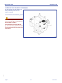
Booklet 4B user manual MOUNTED UNIT Serial number Edition3 10 - 2010 INDEX title page title TECHNICAL INFORMATION ..........................2 Water filling through tank filling hose..... 12 Main components ....................................2 Product mixing ...................................... 13 Technical specifications ...........................3 Preparation of chemical product..................13 Safety devices .........................................3 Mixing with pump and mixer in the cover ....13 Position of signals....................................4 Mixing with control unit and mixer in the cover ..................................................14 INFORMATION ABOUT HANDLING AND INSTALLATION ......................................4 Mixing with Mixer .........................................14 Standard water system plan with manual control unit ......................................16 Transporting.............................................4 Loading and unloading ............................5 Adjustment of the sliding guides ..............5 Water system plan with electric control unit, Mixer, and system washing unit with non-return valve ...................................17 INFORMATION ABOUT USE .........................6 Spraying ................................................ 18 Connecting the equipment to tractor........6 Standard water system plan with manual control unit ......................................18 INFORMATION ABOUT ADJUSTMENTS ......5 Connecting the equipment to tractor (Tractor quick coupling kit).......................7 Water system plan with electric control unit, Mixer, and system washing unit with non-return valve ...................................19 Anti-overturn protection feet ....................8 System washing and emptyng of residual volume ..................................... 20 System diagrams .....................................8 Standard water system plan with manual control unit ........................................8 With standard system ..................................20 Water system plan with electric control unit, Mixer, and system washing unit with non-return valve .....................................9 INFORMATION ABOUT REPLACEMENTS .........................................22 Filter cleaning........................................ 22 Tank filling ..............................................10 Lubrication points diagram .................... 23 Water filling from the upper holes ..........10 Water feeding with tank filling hose from suction filter ................................... 11 233.011 page IMPORTANT SAFETY NOTE The information published in this booklet regards the pointed out with relevant symbols in order to safeguard operational aspects of the operator unit installed on the people from risks. Remember that prudence is irreplaceable. machine. It is however English necessary that you carefully read the Safety is also in the hands of all the operators who interact general safety regulations published in Booklet 1 and those with the machine. -1- user manual Mounted unit Booklet 4B TECHNICAL INFORMATION MAIN COMPONENTS S_018.tif A) Spray product tank. B) Pump. C) Water control unit D) Clean water tank for hand washing. E) Pressure gauge to measure the working pressure F) Clean water tank for system washing. G) Platform for getting on the sprayer H) Tractor quick coupling kit (On request) L) Boom lifting device M) Mixer (upon request) N) Container for clothes Information concerning components that is not included in this manual is detailed in the relevant instruction manuals. The information about the components that is not included in this manual is detailed in the relevant instruction manuals. 233.011 SAFETY DEVICES English -2- user manual Mounted unit Booklet 4B TECHNICAL SPECIFICATIONS Models vary according to drawbar type and tank size. Residual volume The liquid volume that cannot be properly distributed (technical residue) does not exceed 0.5% of nominal volume plus 2 litres per boom meter. S_019.tif Size (mm) Model (Lt) Capacity (Lt) Weight (kg) A B C 900 800 1900 1200 2100 375 1100 1000 1900 1200 2100 380 1300 1200 1900 1200 2100 385 SAFETY DEVICES 233.011 A) Cardan shaft guard: to avoid entanglement with parts of the body. B) Stop valve: device preventing the boom from dropping suddenly in the event of a leak in the hydraulic hose. C) Fixed guard: sliding frame protection. D) Sprayer anti-overturn protection foot: to avoid the overturn risk of the sprayer when it is disconnected from the tractor. E) Cardan shaft support: to support the shaft while disconnected from power take-off. F) Support leg: to support the equipment before disconnection so that reconnection is simpler. G) Extension opening blocking; prevents the unintentional opening of the boom extensions during road circulation. S_020.tif Caution - Warning Check daily that all safety devices are correctly installed and in working order. English -3- user manual Mounted unit Booklet 4B POSITION OF SIGNALS The figure shows the location of all safety plates, while their meaning is explained in booklet 1. Important Make sure that all plates are legible. If they are not, clean or replace, if necessary, ensuring the new ones are placed in the original position. S_021.tif INFORMATION ABOUT HANDLING AND INSTALLATION TRANSPORTING 233.011 Loading and transporting can be carried out in different ways, according to the destination. In all cases the equipment must not be packaged. English -4- user manual Mounted unit Booklet 4B LOADING AND UNLOADING Danger - Warning Lifting and handling must be carried out with the tank empty and using appropriate equipment, by skilled staff specialized in this kind of operation. 1 - Prepare a lifting hook with an adequate loading capacity and connect as shown in the figure below. 2 - Lift slowly, move very gently and avoid all swinging. 3 - Load onto the vehicle and secure using ropes and chocks. Important Insert the forks of the truck into the lifting saddles (A). S_022.tif INFORMATION ABOUT ADJUSTMENTS ADJUSTMENT OF THE SLIDING GUIDES Proceed as follows. 1 - Loosen nut (B). 2 - Adjust adjusting screw (A) to regulate the guides until you obtain a regular sliding with no excessive play. 3 - Tighten counter-nut (B) after this operation. 233.011 S_023.tif English -5- user manual Mounted unit Booklet 4B INFORMATION ABOUT USE CONNECTING THE EQUIPMENT TO TRACTOR Proceed as follows: 1 - Place the arms of the tractor height adjuster level with pins (A). 2 - Stop the engine, apply the parking brake and disengage the ignition key. 3 - Fix the height adjuster arms to pins (A) and insert locking pin (E). 4 - Adjust the top link arm (B) length and fix it to the equipment by means of pin (C) and locking pin (D). Danger - Warning Make sure that pins and locking pins are in the correct position and check their conditions. S_024.tif 5 - Start the tractor engine and perform the lifting by means of the relevant control. 233.011 6 - Adjust the top link arm (B) until the equipment is parallel to the ground. English -6- user manual Mounted unit Booklet 4B CONNECTING THE EQUIPMENT TO TRACTOR (Tractor quick coupling kit) 233001020.TIF S_025.tif Proceed as follows: 1 - Remove boom (F) by means of locking device (G), after removing the safety pin. 8 - Adjust the length of third point (B) and fasten it to the equipment in the correct position by means of the special dowel and the special safety pin so that the machine is parallel to the ground during the working operations. 2 - Insert boom (F) into the lower arms of the tractor and insert the safety pins. 3 - Position the tractor lifting device about 10 cm lower than couplings (H). Danger - Warning Make sure that all safety pins have been inserted in order to avoid the accidental desengagement of the pin arms. Use suitable pins only. 4 - Move the tractor backwards until boom (F) is under couplings (H). 5 - Lift the lifting device util the equipment is connected. 6 - Insert safety pins (P). 233.011 7 - Switch off the motor, activate the parking brake and leave the tractor; remove and keep the ignition key. English -7- user manual Mounted unit Booklet 4B ANTI-OVERTURN PROTECTION FEET S_026.tif Front (C) and rear anti-overturn protection feet (A) increase the sprayer stability when the sprayer is not connected to the tractor. Position 1 - position of the anti-overturn protection feet when parking the equipment. Position 2 - position of the anti-overturn protection feet when the equipment is operating. - Loosen knobs (D) and position the feet in the desired position. Tighten the knobs after the adjustment. - Remove safety pins (B) and orientate the feet in the desired position. Insert the safety pins. SYSTEM DIAGRAMS Standard water system plan with manual control unit S_027.tif 233.011 Legend 1 - Suction filter (filling) 10 - 3-way ball valve 4 - Tank emptying valve 21 - Stainless steel pipes 7 - Suction filter 29 - Clear water tank 8 - Diaphragm pump 30 - Product tank English -8- 33 - Control unit user manual Mounted unit Booklet 4B Water system plan with electric control unit, Mixer, and system washing unit with non-return valve M_019.tif Legend 1 - Suction filter (filling) 13 - Mixer 30 - Product tank 4 - Tank emptying valve 14 - Control unit line filter 34 - Non-return valve 7 - Suction filter 15 - Pressure control engine 35 - Pressure gauge 8 - Diaphragm pump 16 - Main engine 37 - Manifold 9 - Maximum pressure control valve 17 - Tank inside washing valve 40 - Mixer filling lever valve 10 - 3-way ball valve 20 - Solenoid valve assembly 41 - Tank inside washing lever valve 11 - Product transfer valve 21 - Stainless steel pipes 42 - Agitator lever valve in tank 12 - Container washing lever-operated control valve 28 - Distribution line filters 233.011 29 - Clear water tank English -9- user manual Mounted unit Booklet 4B TANK FILLING The tank can be filled in two different ways: - Water filling from the upper holes (page 10); - Water feeding with tank filling hose from suction filter (page 11); - Water filling through tank filling hose (page 12); Important When filling the tank, ensure that hand-washing tank (B) has been filled with clean water and filled it up, if necessary. WATER FILLING FROM THE UPPER HOLES Use an external water source or a tank that is located on a level higher than filling hole (A and C). Fill tank (B) with hand-washing water Important Tank filling opening (A) must be equipped with the basket filter (mesh size 1 mm). Important The tank (B) must be filled with clean water. 233.011 S_028.tif English - 10 - user manual Mounted unit Booklet 4B WATER FEEDING WITH TANK FILLING HOSE FROM SUCTION FILTER S_029.tif Caution - Warning Make sure that no part of the tank-filling hose comes Important Remove the cap by pressing and rotating counter- into contact with the chemical spray products, so clockwise. that the water source does not become polluted. 4 - Connect the tank-filling hose (D) to the coupling (C). Start the tractor and engage the PTO to fill the tank until the required quantity of water is reached. Proceed as follows: 1 - Switch off the motor, activate the parking brake and leave the tractor; remove and keep the ignition key. 5 - Disengage the PTO, stop the engine and remove the ignition key. 2 - Plunge floating filter (A) into the water source (reservoir, external tank, ditch, etc). 6 - When the operation is over, disconnect the hose (D) and replace the cap (B). The machine is ready to start spraying. 233.011 3 - Remove the cap (B) from the coupling (C). English - 11 - user manual Mounted unit Booklet 4B WATER FILLING THROUGH TANK FILLING HOSE M_020.tif 6 - When filling is over, return lever (E) to position 2. Caution - Warning Make sure that no part of the tank-filling hose comes 7 - Reduce the power take-off rpm. 8 - When the operation is over, disconnect the hose (B) and replace the cap (A). The machine is ready to start spraying. into contact with the chemical spray products, so that the water source does not become polluted. 1 - Plunge floating filter (D) into the water source (reservoir, external tank, ditch, etc). 2 - Remove the cap (A) from the coupling (C). 233.011 3 - Connect the tank-filling hose (B) to the coupling (C). 4 - Place the valve levers (E-F-G) in the position shown. 5 - Connect the PTO. English - 12 - user manual Mounted unit Booklet 4B PRODUCT MIXING Preparation of chemical product - In case of accidental contact of the product or mix with the skin, wash immediately with clean water. In case of illness refer to medical assistance, showing the product label. Important Before starting the preparation of the chemical product, adopt all measures that are necessary to avoid contamination danger and risks for men, animals and environment. Caution - Warning Do not dispose of the product, the mix or other pol- In particular: luting material in the environment. Disposal must be - Wear protection clothing to avoid the direct contact with parts of the body, especially in the presence of wounds. - Wear personal protective equipment to protect your face, head and hands, use rubber gloves, dust masks, safety glasses and helmet. - Do not use protection devices that are not in perfect operating conditions, in particular check the state of the gas mask and cab filters. - Keep the chemical products out of the reach of unauthorised persons (especially children and disabled). - Arrange all the equipment that is necessary to handle the chemical product and the mix during the preparation, filling, draining and cleaning of the tank, as well as during the product distribution, adjustment, replacement or add of plant protection products and maintenance operations. - Calculate the exact quantity of product to be mixed according to the surface to be treated and comply with the instructions supplied by the plant protection product manufacturer. Do not mix different products. performed in accordance with the current regulations on waste. M_001.tif Mixing with pump and mixer in the cover 1 - Insert water into the tank until 1/2 ÷ 2/3 of the maximum level is reached (see “Tank filling”). 2 - Add the antifoaming additive (if required). 3 - Enable the pump and turn valve (B) to activate the mixer in the cover (see figure). 4 - Insert the chemical into the tank according to the instructions. 5 - Insert water into the tank until the maximum level is reached (see “Tank filling”). S_030.tif 233.011 6 - Once the operation is completed close valve (B). English - 13 - user manual Mounted unit Booklet 4B Mixing with control unit and mixer in the cover 1 - Insert water into the tank until 1/2 ÷ 2/3 of the maximum level is reached (see “Tank filling”). 2 - Add the antifoaming additive (if required). 3 - Enable the control unit (see booklet 6) and close all boom sections to activate the mixer in the cover (see figure). 4 - Insert the chemical into the tank according to the instructions. 5 - Insert water into the tank until the maximum level is reached (see “Tank filling”). 6 - Once the operation is completed disengage the mixer. Mixing with Mixer S_031.tif To mix the product, follow the procedure below: 1 - Make sure that the system is clean and pour the necessary water for the treatment into the main tank (see page 10, 12). If a sufficient water quantity is present in the main tank, pass to the next phases. 2 - Position the valve levers (A - G- FE - N) as shown in the picture. 3 - Activate the pump. M_002.tif 233.011 4 - Open the valve (C) and insert about 15 cm into the tank (H). M_003.tif English - 14 - user manual Mounted unit Booklet 4B 5 - Open the cover (L), with the valve (C) open and load the chemical product to be mixed. M_004.tif 6 - Open the valve (D) to rinse the chemical product container. Danger - Warning Do not operate the valve (D) until the container is placed on the nozzle, so as to avoid water spills that might hurt the operator. Danger - Warning Do not pollute the environment with empty containers. Dispose of empty containers in accordance with the waste disposal regulations in force in the country of use. 7 - Close the cover back and wait until the liquid level rises to approximately mid-tank. M_005.tif 8 - Open the valve (A) to empty the tank. 9 - Shut off the valve (C). 10- Operate the valve lever (D) to rinse the equipment. 233.011 Danger - Warning Keep the cover closed when you perform this operation, so as to avoid water spills that might hurt the operator. Control through the inspection hole (M). M_006.tif English - 15 - user manual Mounted unit Booklet 4B 11 - Close valve (A), turn lever (N) as shown and turn the levers of valves (G - F - E) to work position. Important In case of accidental contact of the product or the mixture with skin, flush immediately with the fresh water contained in the hand-washing tank. M_007.tif Standard water system plan with manual control unit 233.011 S_032.tif English - 16 - user manual Mounted unit Booklet 4B Water system plan with electric control unit, Mixer, and system washing unit with non-return valve 233.011 M_021.tif English - 17 - user manual Mounted unit Booklet 4B SPRAYING Important The environment and field conditions of the area Proceed as follows for spraying: 1 - Position the levers of valves (A) or (F - G - E) as shown in the figure. where you plan to operate have to be checked every 2 - Connect the tractor PTO (max. 540rpm). time the equipment is set up for spraying. 3 - Unfold the spraying boom. Evaluate the following requirements. 4 - Select the sections of the boom that correspond to the area to be sprayed. - Check whether or not there are electric lines and assess the risks of contact with the spraying booms. - Check the gradient of the land so as to evaluate the most suitable conditions for operating in safety. Always bear in mind the maximum gradients allowed. - In the event of spraying while moving crosswise to the slope, follow the instructions extremely carefully: Boom unfolding stage: always unfold the uphill boom first, and then the downhill boom. Boom folding stage: always fold the downhill boom first, and then the uphill boom. - Never leave the downhill boom alone unfolded. - Keep the forward speed moderate (max. 8-10 km/ h) to prevent the booms from swinging and to keep spraying even. - Before you start spraying an area, make sure there is enough product in the tank. - It is important to be up to date with the weather conditions while spraying. Wind speed should not exceed 5m/sec. 5 - Operate the levers of the water control unit in order to feed the boom and to start the tractor. Important If it is windy, (even below the maximum limit of 5 m/ sec) to prevent the product from drifting, keep the boom low and increase the size of the droplets. Danger - Warning Prevent outsiders from approaching the working area when the equipment is in use. If necessary, stop spraying immediately and get the people in the risk area to move away. 233.011 Standard water system plan with manual control unit M_014.tif English - 18 - user manual Mounted unit Booklet 4B Water system plan with electric control unit, Mixer, and system washing unit with non-return valve 233.011 M_022.tif English - 19 - user manual Mounted unit Booklet 4B SYSTEM WASHING AND EMPTYNG OF RESIDUAL VOLUME Caution - Warning Pollutant substances must be properly disposed of in compliance with current legislation. Special care should be taken to avoid polluting waterways and groundwater with spraying chemicals. Keep product out of reach of children. Important Residual volume is the leftover liquid that cannot be suctioned up and remains on the bottom of the tank. With standard system 233.011 S_033.tif - Place valve lever (A) in the position 2. - Activate the power take-off and spray all the liquid that can be sucked on the surface to be treated. - Switch off the motor, activate the parking brake and leave the tractor; remove and keep the ignition key. - Remove the main lid of the tank and clean the walls with a jet of water. - Place valve lever (A) in the position 1. - Activate the power take-off and spray all the liquid that can be sucked on the surface to be treated. English - 20 - user manual Mounted unit Booklet 4B With system washing and non-return valve M_023.tif - Place valve levers (F - G - E) in the position shown. 233.011 - Activate the power take-off and spray all the liquid that can be sucked on the surface to be treated. - Activate the tank washing system (if present). - If the tank washing system is not present: - Switch off the motor, activate the parking brake and leave the tractor; remove and keep the ignition key. - Remove the main lid of the tank and clean the walls with a jet of water. English - 21 - user manual Mounted unit Booklet 4B - Place a receptacle beneath valve (B), remove cap (A) and open the lever to drain off the residual liquid. - Close the lever again (B) and replace the cap (A). S_015.tif INFORMATION ABOUT REPLACEMENTS FILTER CLEANING - Turn the levers (E - F - G) as shown in the picture M_029.tif 233.011 - Open valve (M) to clean filter (N). - Remove the intake filter (P), mesh size 0.25 mm, and wash it with a water jet. - Remove the in-line bar filters (see leaflet 9) and wash them with a water jet. - Wash the outside of the tanks and the areas in contact with the product with a water jet. F_056.tif English - 22 - user manual Mounted unit Booklet 4B LUBRICATION POINTS DIAGRAM Oil all greasing points and sliding surfaces, particularly whenever the system is washed. Use PERSIAN POLIGREASE 2 grease Important When the lifting device slides with an excessive play, adjust sliding blocks (A) as shown on page 5. The replacement of sliding blocks (A), if it is necessary, shall be carried out only by personnel trained for this intervention. 233.011 S_017.tif English - 23 - user manual Mounted unit 233.011 Booklet 4B English - 24 - user manual