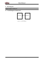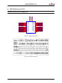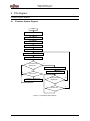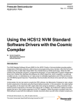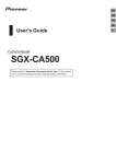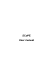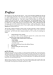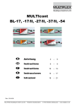
1
The following document contains information on Cypress products.
Colophon
The products described in this document are designed, developed and manufactured as contemplated for general use,
including without limitation, ordinary industrial use, general office use, personal use, and household use, but are not
designed, developed and manufactured as contemplated (1) for any use that includes fatal risks or dangers that, unless
extremely high safety is secured, could have a serious effect to the public, and could lead directly to death, personal injury,
severe physical damage or other loss (i.e., nuclear reaction control in nuclear facility, aircraft flight control, air traffic control,
mass transport control, medical life support system, missile launch control in weapon system), or (2) for any use where
chance of failure is intolerable (i.e., submersible repeater and artificial satellite). Please note that Spansion will not be liable
to you and/or any third party for any claims or damages arising in connection with above-mentioned uses of the products.
Any semiconductor devices have an inherent chance of failure. You must protect against injury, damage or loss from such
failures by incorporating safety design measures into your facility and equipment such as redundancy, fire protection, and
prevention of over-current levels and other abnormal operating conditions. If any products described in this document
represent goods or technologies subject to certain restrictions on export under the Foreign Exchange and Foreign Trade Law
of Japan, the US Export Administration Regulations or the applicable laws of any other country, the prior authorization by the
respective government entity will be required for export of those products.
Trademarks and Notice
The contents of this document are subject to change without notice. This document may contain information on a Spansion
product under development by Spansion. Spansion reserves the right to change or discontinue work on any product without
notice. The information in this document is provided as is without warranty or guarantee of any kind as to its accuracy,
completeness, operability, fitness for particular purpose, merchantability, non-infringement of third-party rights, or any other
warranty, express, implied, or statutory. Spansion assumes no liability for any damages of any kind arising out of the use of
the information in this document.
®
®
®
TM
Copyright © 2013 Spansion Inc. All rights reserved. Spansion , the Spansion logo, MirrorBit , MirrorBit Eclipse ,
TM
ORNAND and combinations thereof, are trademarks and registered trademarks of Spansion LLC in the United States and
other countries. Other names used are for informational purposes only and may be trademarks of their respective owners.
Fujitsu Semiconductor Design (Chengdu) Co., Ltd.
Application Note
MCU-AN-500111-E-10
F²MC-8FX FAMILY
8-BIT MICROCONTROLLER
MB95410H/470H SERIES
ONE PHASE POWER METER
(RN8209) SOLUTION
DISPLAY OPERATION
APPLICATION NOTE
Display Operation V1.0.0
Revision History
Revision History
Version
Date
Updated by
Modifications
1.0.0
6/1/2011
Funny Chen
First Draft : Write the user manual of display function.
This manual contains 12 pages.
Specifications are subject to change without notice. For further information please contact each office.
All Rights Reserved.
The contents of this document are subject to change without notice.
Customers are advised to consult with sales representatives before ordering.
The information, such as descriptions of function and application circuit examples, in this document are presented solely
for the purpose of reference to show examples of operations and uses of FUJITSU SEMICONDUCTOR device; FUJITSU
SEMICONDUCTOR does not warrant proper operation of the device with respect to use based on such information. When
you develop equipment incorporating the device based on such information, you must assume any responsibility arising
out of such use of the information.
FUJITSU SEMICONDUCTOR assumes no liability for any damages whatsoever arising out of the use of the information.
Any information in this document, including descriptions of function and schematic diagrams, shall not be construed as
license of the use or exercise of any intellectual property right, such as patent right or copyright, or any other right of
FUJITSU SEMICONDUCTOR or any third party or does FUJITSU SEMICONDUCTOR warrant non-infringement of
any third-party's intellectual property right or other right by using such information. FUJITSU SEMICONDUCTOR
assumes no liability for any infringement of the intellectual property rights or other rights of third parties which would
result from the use of information contained herein.
The products described in this document are designed, developed and manufactured as contemplated for general use,
including without limitation, ordinary industrial use, general office use, personal use, and household use, but are not
designed, developed and manufactured as contemplated (1) for use accompanying fatal risks or dangers that, unless
extremely high safety is secured, could have a serious effect to the public, and could lead directly to death, personal injury,
severe physical damage or other loss (i.e., nuclear reaction control in nuclear facility, aircraft flight control, air traffic
control, mass transport control, medical life support system, missile launch control in weapon system), or (2) for use
requiring extremely high reliability (i.e., submersible repeater and artificial satellite).
Please note that FUJITSU SEMICONDUCTOR will not be liable against you and/or any third party for any claims or
damages arising in connection with above-mentioned uses of the products.
Any semiconductor devices have an inherent chance of failure. You must protect against injury, damage or loss from such
failures by incorporating safety design measures into your facility and equipment such as redundancy, fire protection, and
prevention of over-current levels and other abnormal operating conditions.
Exportation/release of any products described in this document may require necessary procedures in accordance with the
regulations of the Foreign Exchange and Foreign Trade Control Law of Japan and/or US export control laws.
The company names and brand names herein are the trademarks or registered trademarks of their respective owners.
© 2011 Fujitsu Semiconductor Design (Chengdu) Co., Ltd.
MCU-AN-500111-E-10 – Page 2
Display Operation V1.0.0
Contents
Contents
REVISION HISTORY ............................................................................................................ 2
CONTENTS .......................................................................................................................... 3
1 INTRODUCTION .............................................................................................................. 4
2 BACKGROUND ............................................................................................................... 5
2.1
Overview ................................................................................................................. 5
3 HW DIAGRAM ................................................................................................................. 6
3.1
The HW diagram of display unit............................................................................... 6
4 HW REFERENCE SCH .................................................................................................... 7
5 FW DIAGRAM .................................................................................................................. 8
5.1
Firmware System Diagram ...................................................................................... 8
6 FW FUNCTION LIST........................................................................................................ 9
6.1
API .......................................................................................................................... 9
6.2
HAL ....................................................................................................................... 10
7 ADDITIONAL INFORMATION ....................................................................................... 11
8 APPENDIX ..................................................................................................................... 12
8.1
List of Figures and Tables ..................................................................................... 12
MCU-AN-500111-E-10 – Page 3
Display Operation V1.0.0
Chapter 1 Introduction
1 Introduction
This application note describes how to use One Phase Power Meter (RN8209) solution’s
display function.
Chapter 2 explains the background.
Chapter 3 explains the HW diagram of display function.
Chapter 4 explains the HW reference SCH.
Chapter 5 explains the FW diagram.
Chapter 6 explains the FW function list.
MCU-AN-500111-E-10 – Page 4
Display Operation V1.0.0
Chapter 2 Background
2 Background
Background of display Function
2.1
Overview
On the power meter box, there are 2 keys, display key and program key. The system’s
default display mode is auto roll displaying, and each display page delay for 5 seconds.
When you put down the display key, display mode will change to manual roll displaying. And
if you don’t put down the display key for 30 seconds, display mode will change to auto roll
displaying again.
MCU-AN-500111-E-10 – Page 5
Display Operation V1.0.0
Chapter 3 HW Diagram
3 HW Diagram
Hardware diagram of display unit
3.1
The HW diagram of display unit
8COM LCD
MB95F418
Figure 3-1: Hardware diagram
MCU-AN-500111-E-10 – Page 6
Display Operation V1.0.0
Chapter 4 HW Reference SCH
4 HW Reference SCH
1
2
3
4
5
6
7
8
9
10
11
12
13
BL+
BL27
COM0
COM1
COM2
COM3
COM4
COM5
COM6
COM7
SEG00
SEG01
SEG02
SEG03
SEG04
BL-
LCD_COM0
LCD_COM1
LCD_COM2
LCD_COM3
LCD_COM4
LCD_COM5
LCD_COM6
LCD_COM7
LCD_SEG0
LCD_SEG1
LCD_SEG2
LCD_SEG3
LCD_SEG4
BL+
U10
28
Hardware reference SCH of display unit
SEG05
SEG06
SEG07
SEG08
SED09
SEG10
SEG11
SEG12
SEG13
SEG14
SEG15
SEG16
NC
14
15
16
17
18
19
20
21
22
23
24
25
26
SEGLCD_8COM
Figure 4-1: 8COM LCD Interface
Figure 4-2: 8COM LCD Module
MCU-AN-500111-E-10 – Page 7
LCD_SEG5
LCD_SEG6
LCD_SEG7
LCD_SEG8
LCD_SEG9
LCD_SEG10
LCD_SEG11
LCD_SEG12
LCD_SEG13
LCD_SEG14
LCD_SEG15
LCD_SEG16
Display Operation V1.0.0
Chapter 5 FW diagram
5 FW diagram
Firmware system diagram
5.1
Firmware System Diagram
Start
Init LCDCC1
Init LCDCC2
Init LCDCE1
Init COM and SEG port
Clear the LCD
Build auto-roll display content
Display the first page
If put down the
display key?
Y
Build manual-roll display content
N
N
Update the display page
5s time out?
Y
Update the display page
If put down the
display key?
Y
N
30s time out?
N
Figure 5-1: Firmware System Diagram
MCU-AN-500111-E-10 – Page 8
Y
Display Operation V1.0.0
Chapter 6 FW Function List
6 FW Function List
6.1
API
Table 6-1: FW API List
Function Prototype
Description
void Lcd_Init(void)
LCD module initialization
void LoadLcdPara(INT8U* lcdPara)
Load LCD display parameters from EEPROM
void LcdPowerCtl(INT8U pwrNml)
LCD power on/save control
void LcdPageDisplay(void)
Display various data page on LCD screen
void LcdPageManual(INT8U pageSet)
Manual change LCD page
void LcdPageChange(INT8U pageSet)
LCD screen page up/down control
void* FindPageDispThread(INT8U* targetId)
Find page display thread using data ID
void BuildPowerUpLcdPage(void)
Build Power-up LCD page content
void BuildAutoRollLcdPage(void)
Build auto-rolling LCD page content
void BuildManlRollLcdPage(void)
Build manual-rolling LCD page list
void BuildPowerDnLcdPage(void)
Build power-down LCD page content
void LcdParaReloadEnable(void)
Enable LCD parameter reload using system
reset
void DispSegmentEnergy(INT8U pageMode, INT8U
monthId, INT8U dispSegId)
void DispPrepayBalance(INT8U pageMode)
Display segment energy
void DispCurrentTarrifRate(INT8U pageMode)
Display current tariff rate
void DispUserNumLow8b(INT8U pageMode)
Display user number low 8 bit
void DispUserNumHigh4b(INT8U pageMode)
Display user number high 8 bit
void DispMeterNumLow8b(INT8U pageMode)
Display meter number low 8 bit
void DispMeterNumHigh4b(INT8U pageMode)
Display meter number high 8 bit
void DispErrorNum(INT8U pageMode)
Display error number
void DispVoltage(INT8U pageMode)
Display voltage
void DispLoadCurrent(INT8U pageMode)
Display load current
void DispNeutralCurrent(INT8U pageMode)
Display neutral current
void DispPower(INT8U pageMode)
Display power
void DispPowerFactor(INT8U pageMode)
Display power factor
void DispCurrentDate(INT8U pageMode)
Display current date
void DispCurrentTime(INT8U pageMode)
Display current time
Display prepay balance
MCU-AN-500111-E-10 – Page 9
Display Operation V1.0.0
Chapter 6 FW Function List
6.2
HAL
Table 6-2: FW HAL List
Function Prototype
Description
void LcdCardCommDisp(INT8U value)
void LcdEnergyPurchaseDisp(INT8U onOff)
void LcdEnergyPurchaseDisp(INT8U onOff)
void BcdCount2LcdDigit(INT8U *bcdCount, INT8U *lcdDigit)
Convert 4 bytes of BCD string to 8 digits of
LCD display data string
void LcdMainLineDisp(INT8U* dataStr)
Display main line on LCD screen
void LcdDigitDisp(INT8U digitId, INT8U digitCode)
Display a digit on LCD screen
void LcdColonDisp(INT8U colonTag)
Display colon on LCD screen
void LcdDotDisp(INT8U dpTag)
Display dot-point on LCD screen
void LcdLedTimeSegId(INT8U segId)
Display tariff time-seg LED id
void LcdTxtTimeSegId(INT8U segId)
Display time-seg text id
void LcdDateTimeDisp(INT8U dtState)
Display date/time text
void LcdLastMonthDisp(INT8U month)
Display month
void LcdBattDisp(INT8U battState)
Set LCD battery Display On/Off
void LcdCommDisp(INT8U ch, INT8U commState)
Set LCD Comm Display On/Off
void LcdProgramDisp(INT8U programState)
Set LCD programmable sign Display On/Off
void LcdLockDisp(INT8U lockState)
Set LCD Lock Display On/Off
void LcdKwhDisp(INT8U kwhState)
Set LCD KWh Display On/Off
void LcdKwDisp(INT8U kwState)
Set LCD KW Display On/Off
void LcdRmbDisp(INT8U rmbState)
Set LCD RMB Display On/Off
void LcdEnergyDirDisp(void)
Display Energy direction
INT8U LcdRemoveHeading0(INT8U *buff, INT8U ptPos)
Remove useless heading zero for main display
line
void LcdNegativeSignDisp(INT8U onOff)
Set negative sign Display On/Off
void LcdCosineSignDisp(INT8U onOff)
Set cosine sign Display On/Off
void LcdDatSend(INT8U* dispDat, INT8U size)c
Send a string of display data to LCD controller
module
MCU-AN-500111-E-10 – Page 10
Display Operation V1.0.0
Chapter 7 Additional Information
7 Additional Information
For more Information on FUJITSU semiconductor products, visit the following websites:
English version address:
http://www.fujitsu.com/cn/fsp/services/mcu/mb95/application_notes.html
Chinese version address:
http://www.fujitsu.com/cn/fss/services/mcu/mb95/application_notes.html
MCU-AN-500111-E-10 – Page 11
Display Operation V1.0.0
Chapter 8 Appendix
8 Appendix
8.1
List of Figures and Tables
Table 6-1: FW API List ........................................................................................................... 9
Table 6-2: FW HAL List ........................................................................................................ 10
Figure 3-1: Hardware diagram ............................................................................................... 6
Figure 4-1: 8COM LCD Interface............................................................................................ 7
Figure 4-2: 8COM LCD Module .............................................................................................. 7
Figure 5-1: Firmware System Diagram ................................................................................... 8
MCU-AN-500111-E-10 – Page 12