Transcript
[WIRING PRECAUTIONS]
CL2X8-D1S2
CC-Link/LT Remote I/O Module
Thank you very much for purchasing this product.
Please read this manual thoroughly before starting to use the product and
handle the product properly.
User's Manual
ATTENTION
● Perform correct wiring for the module according to the product’s rated voltage and
terminal arrangement. Connecting to a power supply different from rating or misswiring may cause fire and/or product failure.
● Fix terminal screws securely within the regulated torque. Loose terminal screws
may cause fire and/or malfunction. If the terminal screws are too tight, it may
cause short circuit or erroneous operation due to damage of the screws.
● Make sure foreign objects do not get inside the module, such as dirt and wire
chips. It may cause fire, product failure or malfunction.
[STARTING AND MAINTENANCE PRECAUTIONS]
CL2X8-D1S2-U
WARNING
MODELCODE 13JP23
● Do not touch terminals when the power is on. Doing so could cause an electric
shock.
● Switch off all phases of the externally supplied power used in the system when
cleaning the module or retightening the terminal or module mounting screws. Not
doing so could result in electric shock.
IB(NA)-0800256-D(1406)MEE
© 2003 MITSUBISHI ELECTRIC CORPORATION
SAFETY PRECAUTIONS
[STARTING AND MAINTENANCE PRECAUTIONS]
(Read these precautions before using.)
Please read this manual carefully and pay special attention to safety in order to handle
this product properly. Also pay careful attention to safety and handle the module
properly.
These precautions apply only to Mitsubishi equipment. Refer to the user's manual of
the CPU module to use for a description of the programmable controller system safety
precautions.
Before using this product, please read this manual and the relevant manuals carefully
and pay full attention to safety to handle the product correctly.
In this manual, the safety precautions are classified into two levels: "
WARNING"
and "
CAUTION".
WARNING
Indicates that incorrect handling may cause hazardous
conditions, resulting in death or severe injury.
CAUTION
Indicates that incorrect handling may cause hazardous
conditions, resulting in minor or moderate injury or
property damage.
Under some circumstances, failure to observe the precautions given under
"
CAUTION" may lead to serious consequences.
Observe the precautions of both levels because they are important for personal and
system safety.
Make sure that the end users read this manual and then keep the manual in a safe
place for future reference.
[DESIGN PRECAUTIONS]
WARNING
● Configure an interlock circuit in a sequence program so that the system operates
on the safety side using the communication status information in the event the
data link falls into a communication problem. Otherwise, erroneous output and
malfunction may result in accidents.
● Input could be switched on or off when a problem occurs in the remote I/O
modules. So build an external monitoring circuit that will monitor any input signals
that could cause a serious accident.
CAUTION
● Do not disassemble or modify the module. Doing so may cause failure,
malfunction, injury, or fire.
● Do not drop or apply any strong impact to the module. Doing so may damage the
module.
● Completely turn off the externally supplied power used in the system before
mounting or removing the module. Not doing so could result in damage to the
product.
● Before touching the module, always touch grounded metal, etc. to discharge static
electricity from the human body, etc. Not doing so can cause the module to fail or
malfunction.
[DISPOSAL PRECAUTIONS]
CAUTION
● When disposing of this product, treat it as industrial waste.
PRÉCAUTIONS DE SÉCURITÉ
(Lire ces précautions avant usage.)
Prière de lire attentivement ce manuel. Prêter une attention particulière à tout ce qui a
trait à la sécurité pour utiliser le produit correctement.
Ces précautions ne concernent que l'équipement Mitsubishi. Dans le manuel de
l'utilisateur du module CPU correspondant, voir l'exposé des précautions de sécurité
concernant le système de l'automate programmable.
Avant d'utiliser ce produit, lire attentivement ce manuel ainsi que les manuels auxquels
il renvoie, et toujours considérer la sécurité comme de la plus haute importance en
manipulant le produit correctement.
Dans ce manuel, les précautions de sécurité sont classées en deux niveaux, à savoir :
"
AVERTISSEMENT" et "
ATTENTION"
AVERTISSEMENT
ATTENTION
Attire l'attention sur le fait qu'une négligence peut créer
une situation de danger avec risque de blessures légères
ou de gravité moyennes ou risque de dégâts matériels.
[DESIGN PRECAUTIONS]
CAUTION
● Do not have control cables and communication cables bundled with or placed near
by the main circuit and/or power cables. Wire those cables at least 100mm(3.94
inch) away from the main circuit and/or power cables. It may cause malfunction
due to noise interference.
Attire l'attention sur le fait qu'une négligence peut créer
une situation de danger avec risque de mort ou de
blessures graves.
Dans certaines circonstances, le non-respect d'une précaution de sécurité introduite
sous le titre "
ATTENTION"peut avoir des conséquences graves.
Les précautions de ces deux niveaux doivent être observées dans leur intégralité car
elles ont trait à la sécurité des personnes et aussi du système.
Veiller à ce que les utilisateurs finaux lisent ce manuel qui doit être conservé
soigneusement à portée de main pour s'y référer autant que de besoin.
● Utiliser le module dans un environnement conforme aux spécifications générales
présentées dans ce manuel. L'utilisation de ce module dans un environnement
autre que celui prévu dans les spécifications générales peut être à l'origine d'un
choc électrique, d'un départ de feu ou d'un dysfonctionnement, ou peut
endommager ou détériorer le produit.
● Éviter tout contact direct avec les parties conductrices du module.
Cela pourrait être à l'origine de dysfonctionnements ou autres problèmes avec le
module.
● Serrer le module fermement avec un rail DIN ou avec des vis de fixation serrées
dans les limites du couple de serrage prescrit. Si le serrage des vis est insuffisant,
il y a risque de chute du module, de court-circuit ou de dysfonctionnement. Un
serrage excessif peut endommager les vis et il y a risque de détachement du
module et de court-circuit.
[PRÉCAUTIONS DE CÂBLAGE]
AVERTISSEMENT
● Couper complètement l'alimentation externe utilisé par le système avant de mettre
avant le câblage ou le raccordement de câbles. Ne pas couper complètement
toutes les alimentations expose au risque de chocs électriques et
d'endommagement du produit.
ATTENTION
● Les vis des bornes qui restent inutilisées doivent toujours être serrées.
Faute de quoi, il y a danger de court-circuit par contact avec les bornes-barres
sans soudure.
● Effectuer le câblage du module correctement, compte tenu de la tension nominale
du produit et en respectant l'affectation des bornes. Le raccordement d'une
alimentation de tension nominale différente ou une erreur de câblage peuvent être
à l'origine d'un départ de feu et/ou d'une panne du produit.
● Fixer les vis de borne fermement en serrant au couple prescrit. Des vis de bornes
desserrées peuvent être à l'origine d'un départ de feu et/ou de
dysfonctionnements. Si serrage excessif des vis de bornes peut les endommager
et être à l'origine d'un court-circuit ou d'un fonctionnement erratique.
● Veiller à éviter toute pénétration d'impuretés, copeaux de câblage ou autre corps
étranger dans le module. Cela pourrait être à l'origine d'un départ de feu, ou du
panne ou d'un dysfonctionnement du produit.
[PRÉCAUTIONS DE DÉMARRAGE ET DE MAINTENANCE]
AVERTISSEMENT
● Ne pas toucher aux bornes quand l'appareil est sous tension.Cela pourrait être à
l'origine d'un choc électrique.
● Avant le nettoyage du module ou le resserrage des vis de borne ou des vis de
fixation du module, couper les alimentations externes utilisées par le système sur
toutes les phases. Faute de quoi, il y a risque de choc électrique.
[PRÉCAUTIONS DE DÉMARRAGE ET DE MAINTENANCE]
[PRÉCAUTIONS DE MISE AU REBUT]
ATTENTION
[PRÉCAUTIONS DE CONCEPTION]
CAUTION
● Use the module in an environment that meets the general specifications contained
in this manual. Using this module in an environment outside the range of the
general specifications could result in electric shock, fire, erroneous operation, and
damage to or deterioration of the product.
● Do not directly touch the module’s conductive parts.
Doing so could cause malfunction or trouble in the module.
● Tighten the module securely using DIN rail or installation screws within the
specified torque range. If the screws are too lose, the module may drop from its
installation position, short circuit, or malfunction. If the screws are too tight, the
screws may be damaged, which may cause the module to drop from its installation
position or short circuit.
● Lors de sa mise au rebut, ce produit doit être traité comme un déchet industriel.
AVERTISSEMENT
● Prévoir dans le programme séquentiel un circuit de verrouillage sur la base des
informations d'état de la communication, de façon à maintenir la sécurité de
fonctionnement du système dans l'éventualité d'un problème de communication
affectant la liaison de données. Faute de quoi, une sortie erronée ou un
dysfonctionnement pourrait être à l'origine d'accidents.
● L'entrée peut être activée ou désactivée à la survenance d'un problème dans les
modules E/S distants. On constituera donc un circuit de surveillance externe
couvrant tous les signaux d'entrée qui pourraient être à l'origine d'un accident
grave.
[PRÉCAUTIONS DE CONCEPTION]
[WIRING PRECAUTIONS]
ATTENTION
WARNING
● Ne pas grouper ni placer à proximité les câbles de commande ou câbles de
communication avec les câbles des circuits principaux et/ou d'alimentation. Câbler
en plaçant ces câbles à une distance d'au moins 100mm (3,94 pouces) des câbles
des circuits principaux ou de l'alimentation. Cela pourrait être à l'origine d'un bruit
parasite entraînant des dysfonctionnements.
● Completely turn off the externally supplied power used in the system when
installing or placing wiring. Not completely turning off all power could result in
electric shock or damage to the product.
WIRING PRECAUTIONS]
CAUTION
● Terminal screws which are not to be used must be tightened always.
Otherwise there will be a danger of short circuit against the bare solderless
terminals.
Item
Description
1)
Operating
status
indicator
LEDs
LED name Confirmation details
Max. simultaneous ON input 100%
points
ON voltage/ON current
PW
On: Power supply on.
Off: The power supply is turned off or the voltage
drop is too large.
L RUN
On: Normal communication.
Off: Communication cutoff
(time expiration error).
19V or higher/3mA or higher
OFF voltage/OFF current
11V or lower/1.7mA or lower
Input resistance
5.6k
Response Response time
time
setting
0.5ms (High speed
response type)
L ERR.
1.5ms (Standard type)
OFF
ON
TYP.
0.05 ms
-
MAX.
0.1 ms
1.5ms
ON
OFF
TYP.
0.2 ms
-
MAX.
0.5 ms
1.5 ms
Common wiring method
8 points/1 common (terminal block 2-wire type)
Input method
Positive common/negative common shared type
Number of stations occupied In 4-point mode: Occupies 2 stations
In 8 or 16-point mode: Occupies 1 station
Module
Voltage
power supply Current
consumption
Current on
startup
Noise durability
0 to 7
24V DC (-15 to +20%) (ripple ratio : within 5%)
2)
40mA or lower (When 24V DC and all point is on)
70mA or lower (24V DC)
DC type noise voltage 500Vp-p, noise width 1µs, noise
carrier frequency 25 to 60Hz (noise simulator
condition)
First transient/noise burst IEC 61000-4-4 : 1kV
Withstand voltage
500V AC for 1 minute between primary (external DC
terminal) and secondary (internal circuit)
Insulation resistance
10M or more between primary (external DC terminal)
and secondary (internal circuit) when measured with a
500V DC insulation resistance tester
Protection class
IP2X
Weight
0.12kg
I/O part connection method
Méthode de raccordement
de la partie E/S
2-piece 20-point spring clamp terminal block
Bornier à étrier 2-pièces 20-points
Module installation method
DIN rail installation, mounted by screws of type
M4×0.7 mm×16 mm or larger, Can be installed in six
directions
Applicable wire size
Taille du fil à utiliser
0.3 to 1.5mm2 (AWG22 to 16)
0,3 à 1,5 mm2 (22 à 16 AWG)
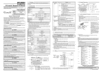
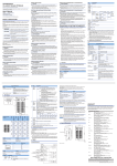
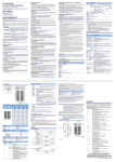
3. Part Names
3)
4)
5)
This section explains the names of the components for the remote I/O module.
6)
1)
3)
Response
time setting
switch
(SW8)
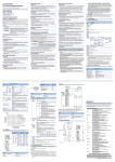
Station
number
setting
switches
(SW1 to 7)
Connector
for CCLink/LT
interface
Select "10", "20" or "40" to set the ten’s place of the station
number.
Select "1","2","4" or "8" to set the one’s place of the station
number.
All switches are set to OFF at shipment from the factory.
Always set the station number within the range of 1 to 64.
A setting error occurs and "L ERR." LED flickers if the value
outside the range 1 to 64 is set.
(Example) Set the switches as below when setting the station
number to 32:
Station Ten’s place
number 40
20
10
8
4
2
1
32
ON
OFF
OFF
ON
OFF
OFF
ON
One’s place
4)
5)
6)
4 3 2 1
LINK/PW
Pin
No.
Signal [Terminal numbers and signal names]
name
1
+24V
2
DA
DC24A DC24A
3
DB
2
4
Bro
[Numéros de
broche et noms des che
N°
signaux]
4 3 2 1
LINK/PW
24G
3
5
7
X0
4
9
X1
6
11
X2
8
15
13
X4
X3
10
12
17
X5
19
X6
16
14
X7
18
20
DC24B DC24B COMB COMB COMB COMB COMB COMB COMB COMB
1
2
DC24A
DC24B
+24V
2
DA
3
DB
24G
3
5
DC24A DC24A
2
4
7
X0
9
X1
6
11
X2
8
X4
X3
10
15
13
12
17
X5
14
Specifications
0 to 55°C
Operating
0 à 55 °C
ambient
temperature
Températur
e ambiante
de
fonctionne
ment
Storage
-25 to 75°C
ambient
temperature
Operating
ambient
humidity
5 to 95%RH, non-condensing
Storage
ambient
humidity
Compliant
with JIS B
3502 and Under
IEC
intermittent
61131-2
vibration
Frequency Constant
Half
Sweep
acceleration amplitude count
5 to 8.4Hz 8.4 to
150Hz
9.8m/s2
Under
5 to 8.4Hz continuous 8.4 to
4.9m/s2
vibration
150Hz
Shock
resistance
3.5mm
-
10 times
each in
X, Y, Z
directions
1.75mm
-
-
Compliant with JIS B 3502 and IEC 61131-2
(147 m/s2, 3 times each in 3 directions X, Y, Z)
Operating
No corrosive gases
atmosphere
Operating
altitude
0 to 2000m
Installation
location
Inside a control panel *3
Overvoltage II or less
category *1
Pollution
degree *2
2 or less
*1 This indicates the section of the power supply to which the equipment is assumed
to be connected between the public electrical power distribution network and the
machinery within premises.
Category II applies to equipment for which electrical power is supplied from fixed
facilities. The surge voltage withstand level for up to the rated voltage of 300V is
2500V.
*2 This index indicates the degree to which conductive material is generated in terms
of the environment in which the equipment is used.
Pollution level 2 is when only non-conductive pollution occurs. A temporary
conductivity caused by condensing must be expected occasionally.
*3 It can also be used in an environment other than on the control panel if the
conditions such as usage ambient temperature and humidity are satisfied.
2.2 Performance specifications
The performance specifications for the remote I/O module are shown in the following
table.
Type CL2X8-D1S2
Alimentation externe de la partie entrée
24Vcc
Terminal block for I/O interface (Negative Bornier pour interface E/S (commun
common)
négatif)
Connector for CC-Link/LT interface
Connecteur pour interface CC-Link/LT
Terminal block for I/O interface (Positive
common)
Bornier pour interface E/S (commun
positif)
Insulation
Isolation
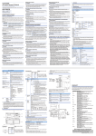
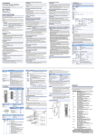
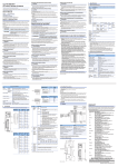
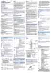
6. External Dimensions
69 (2.72)
60.5(2.38) 0.4(0.02)
4.5 5.1 elongated mounting hole (M4 screw)
4.5
10
(0.18)
(0.39)
4
(0.16)
Center of DIN rail
Hook for installing the module on a DIN rail.
40 (1.57)
4.5 installation hole (M4 screw)
Unit: mm (inch)
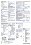
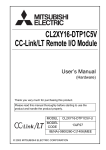
7. Cable Installation Procedure
Screw location
Clamping torque range
Module mounting screw (M4 screw)
0.78 to 1.08 Nm
Precaution for installing or removing cables
Terminal block mounting screw (M3 screw)
0.42 to 0.58 Nm
1. Insert only one wire into the circular shaped hole of the spring clamp terminal
block.
Inserting two or more wires may result in a poor contact to the terminal part.
2. Strip the wire according to the specification. If the wire strip length is toolong, the
exposed conductive part may cause electric shock or short circuit. If the wire strip
length is too short, it may result in a poor contact to the spring clamp terminal part.
3. When using a spring clamp terminal block tool, follow the instruction below. Failure
to do so may cause damage of the spring clamp terminal part or the terminal block
resin part.
• Use a dedicated tool for a spring clamp terminal block.
• Do not insert the wire or the bar solderless terminal before inserting the tool into the
square shaped hole.
• Insert the tool vertically into the hole.
2. When using a DIN rail, attach the DIN rail after taking the following items into
consideration:
• Applicable DIN rail types (conform to JIS C 2812)
TH35-7.5Fe
TH35-7.5Al
• Interval between the DIN rail’s installation screws
Tighten the screws using a pitch of 200mm (7.87in.) or less when attaching a DIN rail.
3. To attach the remote I/O module to the DIN rail, press the centerline area of the
DIN rail hook beneath the module until a click is heard.
4. Maintain some distance between the module and other components and parts, 10
mm from the top and 50mm (1.97in.) from the bottom of the module, in order to
improve ventilation and to make replacement of the module easy if a remote I/O
module is installed on a board.
5. Install the remote I/O module on a level surface. If the surface is uneven,
unnecessary force is applied to the printed circuit board, causing malfunctions.
1. Insert the tool vertically all the way inside the square shaped hole of the remote I/O
module.
2. Insert the wire or the bar solderless terminal into the circular shaped hole, and
remove the tool from the hole.
3. Check that the wire or the bar solderless terminal is firmly clamped by pulling it
lightly.
WARRANTY
French
4
(0.16)
8 points
1. Insert the tool vertically all the way inside the square shaped hole of the remote I/O
module.
2. Pull the wire or the bar solderless terminal out of the hole.
English
Square shaped hole
Circular shaped hole
Tool
19
X6
16
Item
Cable removal
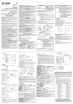
External power supply of the input part
24 VDC
Wire
1
DC/DC
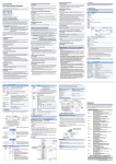
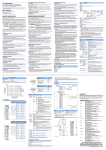
All COM B and DC24B terminals are connected within the module (common).
The power to the module is supplied via the power adapter.
Toutes les bornes COM B et DC24B sont connectées à l'intérieur du module
(commun). L'alimentation du module se fait via l'adaptateur d'alimentation.
Signal [Numéros de borne et noms des signaux]
name
1
4
1
(Negative common)
1
+24V
2
DA
DB
External power 3
4
24G
supply of the
Terminal block
input part
for I/O interface
24 VDC (Positive common)
- +
DC24A
1
DC24B
2
DC24A
3
DC24B
4
X0
5
COM B
6
X1
7
COM B
8
X2
9
10 COM B
11 X3
12 COM B
13 X4
14 COM B
15 X5
16 COM B
17 X6
18 COM B
19 X7
20 COM B
Connector for CC-Link/LT communication line and module power
supply.
4. Handling Precautions
2)
-
Terminal block
for I/O interface
Displays the ON/OFF status of the input (turned on
in the ON status and turned off in the OFF status).
Terminal
Terminal block for connecting input signals and external power
block for I/O supply of the input part.
interface
Hook for
DIN rail
+
On: Indicates that a communication data error has
occurred or the setting switch is outside the
allowable range.
Flicker at regular intervals:
Indicates that the setting switch has been
changed while current is being conducted. (The
module continues to operate even while the
LED is flickering. The changed settings will be
reflected when the power has been restored.)
Flicker at irregular intervals:
Indicates that the terminal resistor is left
unconnected or that the module or connection
cable are affected by noise.
Off: Normal communication.
Set the response time (OFFON/ONOFF time) of the remote
I/O module.
OFF is set as default (factory-set).
Noise may be taken in as input, if high speed response type is
set.
Be sure to set response time in consideration of the environment.
ON: 0.5ms (High speed response type)
OFF: 1.5ms (Standard type)
CL2X8-D1S2
Insulation
External power
supply of the
input part
24 VDC
1. Tighten the terminal screws for the module to the specified torque shown below.
Insufficient tightening torque could result in shorts, failures or malfunction.
[Pin numbers and
signal names]
The General specifications for the remote I/O module are shown in the following table.
Cable Installation
Connector for
CC-Link/LT interface
22 (0.87)
Approx. 4mA
5. Wiring
No.
4
(0.16)
Rated input current
(1) Mitsubishi programmable controller ("the PRODUCT") shall be used in
conditions;
i) where any problem, fault or failure occurring in the PRODUCT, if any, shall not
lead to any major or serious accident; and
ii) where the backup and fail-safe function are systematically or automatically
provided outside of the PRODUCT for the case of any problem, fault or failure
occurring in the PRODUCT.
(2) The PRODUCT has been designed and manufactured for the purpose of being
used in general industries.
MITSUBISHI SHALL HAVE NO RESPONSIBILITY OR LIABILITY (INCLUDING,
BUT NOT LIMITED TO ANY AND ALL RESPONSIBILITY OR LIABILITY BASED
ON CONTRACT, WARRANTY, TORT, PRODUCT LIABILITY) FOR ANY
INJURY OR DEATH TO PERSONS OR LOSS OR DAMAGE TO PROPERTY
CAUSED BY the PRODUCT THAT ARE OPERATED OR USED IN
APPLICATION NOT INTENDED OR EXCLUDED BY INSTRUCTIONS,
PRECAUTIONS, OR WARNING CONTAINED IN MITSUBISHI'S USER,
INSTRUCTION AND/OR SAFETY MANUALS, TECHNICAL BULLETINS AND
GUIDELINES FOR the PRODUCT.
0.2 (0.01)
24V DC
CONDITIONS OF USE FOR THE PRODUCT
49 (1.93)
Rated load voltage
2.1 General Specifications
Item
Type CL2X8-D1S2
Photocoupler isolation
2. Specifications
Number of inputs
Item
Isolation method
1. Overview
Vibration
resistance
ATTENTION
● Ne pas démonter ni modifier le module. Cela pourrait être à l'origine de pannes, de
dysfonctionnements, de blessures ou d'un départ de feu.
● Ne pas faire tomber le module, ni le soumettre à de forts chocs. Cela risquerait
d'endommager le module.
● Couper complètement l'alimentation externe utilisé par le système avant de mettre
en place ou de retirer le module. Faute de quoi, il y a risque d'endommagement du
produit.
● Avant de toucher au module, se débarrasser de la charge électrostatique
qu'accumule le corps humain en touchant un objet métallique raccordé à la terre.
Le non-respect de cette précaution peut être à l'origine de pannes ou de
dysfonctionnements du module.
[INSTALLATION PRECAUTIONS]
("Prohibited Application")
Prohibited Applications include, but not limited to, the use of the PRODUCT in;
Nuclear Power Plants and any other power plants operated by Power
companies, and/or any other cases in which the public could be affected if any
problem or fault occurs in the PRODUCT.
Railway companies or Public service purposes, and/or any other cases in
which establishment of a special quality assurance system is required by the
Purchaser or End User.
Aircraft or Aerospace, Medical applications, Train equipment, transport
equipment such as Elevator and Escalator, Incineration and Fuel devices,
Vehicles, Manned transportation, Equipment for Recreation and Amusement,
and Safety devices, handling of Nuclear or Hazardous Materials or Chemicals,
Mining and Drilling, and/or other applications where there is a significant risk of
injury to the public or property.
Notwithstanding the above, restrictions Mitsubishi may in its sole discretion,
authorize use of the PRODUCT in one or more of the Prohibited Applications,
provided that the usage of the PRODUCT is limited only for the specific
applications agreed to by Mitsubishi and provided further that no special quality
assurance or fail-safe, redundant or other safety features which exceed the
general specifications of the PRODUCTs are required. For details, please
contact the Mitsubishi representative in your region.
This user’s manual explains specifications and names of individual parts of the CL2X8D1S2 type CC-Link/LT remote I/O module (hereinafter abbreviated as remote I/O
module).
[PRÉCAUTIONS DE CÂBLAGE]
41 (1.61)
MODEL
[PRÉCAUTIONS D'INSTALLATION]
CAUTION
Mitsubishi will not be held liable for damage caused by factors found not to be the
cause of Mitsubishi; machine damage or lost profits caused by faults in the Mitsubishi
products; damage, secondary damage, accident compensation caused by special
factors unpredictable by Mitsubishi; damages to products other than Mitsubishi
products; and to other duties.
Country/Region Sales office/Tel
U.S.A
Mitsubishi Electric Automation Inc.
500 Corporate Woods Parkway Vernon Hills, IL 60061, U.S.A.
Tel : +1-847-478-2100
Brazil
MELCO-TEC Rep. Com.e Assessoria Tecnica Ltda.
Rua Correia Dias, 184, Edificio Paraiso Trade Center-8 andar
Paraiso, Sao Paulo, SP Brazil
Tel : +55-11-5908-8331
Germany
Mitsubishi Electric Europe B.V. German Branch
Gothaer Strasse 8 D-40880 Ratingen, GERMANY
Tel : +49-2102-486-0
U.K
Mitsubishi Electric Europe B.V. UK Branch
Travellers Lane, Hatfield, Hertfordshire., AL10 8XB, U.K.
Tel : +44-1707-276100
Italy
Mitsubishi Electric Europe B.V. Italian Branch
Centro Dir. Colleoni, Pal. Perseo-Ingr.2
Via Paracelso 12, I-20041 Agrate Brianza., Milano, Italy
Tel : +39-039-60531
Spain
Mitsubishi Electric Europe B.V. Spanish Branch
Carretera de Rubi 76-80,
E-08190 Sant Cugat del Valles, Barcelona, Spain
Tel : +34-93-565-3131
France
Mitsubishi Electric Europe B.V. French Branch
25, Boulevard des Bouvets, F-92741 Nanterre Cedex, France
Tel : +33-1-5568-5568
South Africa
Circuit Breaker Industries Ltd.
Private Bag 2016, ZA-1600 Isando, South Africa
Tel : +27-11-928-2000
China
Mitsubishi Electric Automation (China) Ltd.
4/F Zhi Fu Plazz, No.80 Xin Chang Road, Shanghai 200003,
China
Tel : +86-21-6120-0808
Taiwan
Setsuyo Enterprise Co., Ltd.
6F No.105 Wu-Kung 3rd.Rd, Wu-Ku Hsiang,
Taipei Hsine, Taiwan
Tel : +886-2-2299-2499
Korea
Mitsubishi Electric Automation Korea Co., Ltd.
1480-6, Gayang-dong, Gangseo-ku Seoul
157-200, Korea
Tel : +82-2-3660-9552
Singapore
Mitsubishi Electric Asia Pte, Ltd.
307 Alexandra Road #05-01/02,
Mitsubishi Electric Building, Singapore 159943
Tel : +65-6470-2480
Thailand
Mitsubishi Electric Automation (Thailand) Co., Ltd.
Bang-Chan Industrial Estate No.111 Moo 4, Serithai Rd,
T.Kannayao, A.Kannayao, Bangkok 10230 Thailand
Tel : +66-2-517-1326
Indonesia
P.T. Autoteknindo Sumber Makmur
Muara Karang Selatan, Block A/Utara
No.1 Kav. No.11 Kawasan Industri Pergudangan
Jakarta - Utara 14440, P.O.Box 5045 Jakarta, 11050 Indonesia
Tel : +62-21-6630833
India
Messung Systems Pvt, Ltd.
Electronic Sadan NO:III Unit No15, M.I.D.C Bhosari,
Pune-411026, India
Tel : +91-20-2712-3130
Australia
Mitsubishi Electric Australia Pty. Ltd.
348 Victoria Road, Rydalmere, N.S.W 2116, Australia
Tel : +61-2-9684-7777
X7
18
20
DC24B DC24B COMB COMB COMB COMB COMB COMB COMB COMB
Wire strip length:
8mm to 11mm
HEAD OFFICE : TOKYO BUILDING, 2-7-3 MARUNOUCHI, CHIYODA-KU, TOKYO 100-8310, JAPAN
NAGOYA WORKS : 1-14, YADA-MINAMI 5-CHOME, HIGASHI-KU, NAGOYA, JAPAN
When exported from Japan, this manual does not require application to the Ministry
of Economy, Trade and Industry for service transaction permission.
Specifications subject to change without notice.