1
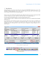
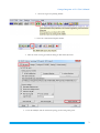
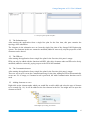
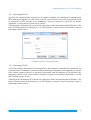
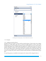
Omega Integrator
User's Manual
version 0.2.0
29. January 2014
Omega Integrator v0.2.0 User's Manual
Table of Contents
1.Introduction.......................................................................................................................................2
2.Overview of the program...................................................................................................................4
2.1 Structure....................................................................................................................................5
2.2 The Substation tree...................................................................................................................6
2.3 The IED tree..............................................................................................................................6
2.4 The Communication tree...........................................................................................................6
2.5 Adding elements to a tree..........................................................................................................6
2.6 Deleting elements from a tree...................................................................................................7
2.7 Adding an IED..........................................................................................................................7
2.8 Generating SCD file..................................................................................................................7
2.9 Generating CID file..................................................................................................................8
2.10 IEC 61850 Enumerations........................................................................................................9
2.11 Examples...............................................................................................................................11
2.11.1 Adding an external reference.........................................................................................11
2.12 Limitations of the demo version...........................................................................................12
3.Appendix.........................................................................................................................................13
1
Omega Integrator v0.2.0 User's Manual
1. Introduction
Omega Integrator can only be started from the OmegaCAD ELEKTRO Engineering system. The
designing of digital substations starts with creating the single line plan. Here are the steps to get
from OmegaCAD ELEKTRO to Omega Integrator:
Select a project, and a field for the single line plan. Single line plans can only be created on the field
with the common project plans. Make sure the field's status is set as planned (fig. 1).
Use the single line planning module to create the single line plan (fig. 2).
After the single line plan is finished, stop the module and switch to the communication planning
module (fig. 3).
For the Integrator, the substation topology must be generated. This can be done by the SSD export
dialog (fig. 4 And 5). It is important, to regenerate the SSD every time the single line plan is
modified. When the SSD generation is done, the System Configurator (Omega Integrator) can be
started (fig. 6).
1. Select a field for the single line plan
2
Omega Integrator v0.2.0 User's Manual
2. Select the single line planning module
3. Select the communicational plan module
4. Click the button to bring forward the dialog for IEC 61850 functions.
5. Create the SSD file, and the substation topology for the Omega Integrator
3
Omega Integrator v0.2.0 User's Manual
6. Start the Omega Integrator
2. Overview of the program
7. An overview of the interface of Omega Integrator
4
Omega Integrator v0.2.0 User's Manual
2.1 Structure
The interface consists of a menu (fig. 8), and four panes (fig. 9). The menu is located at the top, and
the function in order are:
•
Add IED: see chapter Adding an IED
•
Add Communication: Creates a Communication tag with the mandatory elements (a
Subnetwork and a ConnectedAP) Only active, if there is no Communication tag present in
the Communication tree.
•
Generate SCD file: see chapter Generating SCD file
•
Generate CID file: see chapter Generating CID file
•
Save: Saves the data
•
About: Shows an information about the product
•
Exit: Saves the data and exists the application. The arrangement of the panes and the size of
the main window will be preserved.
8. The menu of Omega Integrator
There are four panes, which contain the
•
Substation tree
•
IED tree
•
Communication tree
•
Properties of the selected element
These panes can be freely sized, moved, even outside the main window. The arrangement is
preserved when the application closes, so feel free to create the order you prefer.
Right clicking on the elements brings forward the context menu, which contains all the functions
regarding the element. If a function is not available for some reason, it cannot be selected (ie. no
more elements can be added, or the element cannot be deleted, because it is mandatory). There is no
context menu on the Substation tree, since the topology can only be altered in OmegaCAD Elektro
Engineering.
5
Omega Integrator v0.2.0 User's Manual
9. The four panes of the interface
2.2 The Substation tree
After starting the application from a single line plan for the first time, this pane contains the
topology of the substation.
The elements in the substation tree are from the single line plan of the OmegaCAD Engineering
system. The elements in this tree cannot be modified (added or removed), only the properties of the
elements can be altered.
2.3 The IED tree
After starting the application from a single line plan for the first time, this pane is empty.
IEDs can only be added with the function Add IED. After this, elements under an IED can be freely
modified (added or removed), paying respect to the IEC61850 standard.
2.4 The Communication tree
After starting the application from a single line plan for the first time, this pane is empty.
There are two ways to create the Communication tag for the plan: adding an IED will automatically
create one if it is empty, or if manual work is preferred, the Add Communication function can be
used.
2.5 Adding elements to a tree
Right click on the element under which you would like to add a child, and select the type of element
to be created (fig. 10). It will be added as the last element in the list. You might need to open the
element to find it.
10. Example of creating an element
6
Omega Integrator v0.2.0 User's Manual
2.6 Deleting elements from a tree
Right click on the element which you want to be removed from the tree, and select the Delete action
(fig. 11). It will remove the selected element and all the child element of that (fig. 12).
11. Deleting an element from the tree (1)
12. Deleting an element from the tree (2)
2.7 Adding an IED
An ICD file is needed for an IED to be added. After selecting the file, set a name for the device, and
select which subnetwork should contain it. If an already existing subnetwork is selected from the
list, a new ConnectedAP will be created under it, with reference to the newly created IED's
AccessPoint. If a name is typed for the subnetwork, it will be created with the ConnectedAP under
it. If there might be no Communication tag, it will be created also.
DataTypeTemplates, though those are not visible in this version, are also read with this function.
13. Dialog window for adding an IED
7
Omega Integrator v0.2.0 User's Manual
2.8 Generating SCD file
An SCD file contains all the elements for the digital substation (the Substation, Communication,
IEDs, DataTypeTemplates). For this to be created, a name need to be set for the file (preferably with
an extension of SCD, but that is not mandatory), and an id need to be given for the header.
Optionally, a version and a revision can be set also.
Clicking on the OK button will create the file, and open it in the Notepad program of Windows. The
Show in Folder button will navigate to it in File Explorer, to make it more convenient to open it
with another editor/viewer.
14. Dialog window for generating SCD files
2.9 Generating CID file
A CID file contains information for chosen IEDs in the substation (optionally the Substation, the
Communication is mandatory, at least one IED, and DataTypeTemplates is also mandatory). For this
to be created, a name need to be set for the file (preferably with an extension of CID, but that is not
mandatory), IED(s) to be selected and an id need to be given for the header. Optionally, a version
and a revision can be set also.
Clicking on the OK button will create the file, and open it in the Notepad program of Windows. The
Show in Folder button will navigate to it in File Explorer, to make it more convenient to open it
with another editor/viewer.
8
Omega Integrator v0.2.0 User's Manual
15. Dialog window for generating CID files
2.10 IEC 61850 Enumerations
The IEC 61850 standard defines enumeration for many properties. The value of these properties can
only be set by choosing one of these (see fig. 16).
These enumerations are stored in an XML file named OmegaIntegratorEnums.xml, and can be
customized by the user. Values can be added, removed or edited, but no new enumerations can be
created (if there is a need for other property values to be restricted by enumerations, please contact
Omega-Soft Ltd.).
The structure of the file:
<OmegaIntegratorEnums>
<tEnum>
<Value>...</Value>
[…]
</tEnum>
[...]
<OmegaIntegratorEnums>
9
Omega Integrator v0.2.0 User's Manual
16. Setting the LN class property uses an enumeration as value set
2.11 Examples
2.11.1 Adding an external reference
Navigate to the LN for which you want to add an external reference. If not present create an Inputs
under the LN. Under Inputs, there must be at least one ExtRef element, so select it, and in the
Properties pane you will see the data you can set for the external signal. Let's say we need to bind a
specific data attribute from a different IED. The attributes are ordered the way they go in the tree
structure, from top to bottom. First select the IED. When it is done, the LD instances are loaded in
the list if the LdInst property. Selecting the LD instance loads the prefixes under that instance, and
so on. Not every property need to be filled, but for a specific DA, we should set all of them to
specify it correctly. Every time a selection is made, the lists under that are reloaded with the proper
data.
If a specifying property is modified, the description of the element will be changed in the tree.
10
Omega Integrator v0.2.0 User's Manual
17. Adding an external reference
2.12 Limitations of the demo version
There are some limitation in the demo version, such as:
•
it can only be used for 30 days, counting from the date of the first installation
•
the Save function is inactive
•
only 3 IEDs can be added to the substation per session (after restarting the application
another three devices can be added)
11
Omega Integrator v0.2.0 User's Manual
3. Appendix
Omega Integrator, Copyright (c) 2013-2014, Omega-Soft Ltd. All rights reserved.
http://www.omegasoft.hu
http://www.omegasoft.hu/en
http://www.omegacad.ru
Omega Integrator uses Avalondock.
Avalondock, Copyright (c) 2007-2013, Xceed Software Inc. All rights reserved.
THIS SOFTWARE IS PROVIDED BY THE COPYRIGHT HOLDERS AND CONTRIBUTORS
"AS IS" AND ANY EXPRESS OR IMPLIED WARRANTIES, INCLUDING, BUT NOT
LIMITED TO, THE IMPLIED WARRANTIES OF MERCHANTABILITY AND FITNESS FOR A
PARTICULAR PURPOSE ARE DISCLAIMED. IN NO EVENT SHALL THE COPYRIGHT
HOLDER OR CONTRIBUTORS BE LIABLE FOR ANY DIRECT, INDIRECT, INCIDENTAL,
SPECIAL, EXEMPLARY, OR CONSEQUENTIAL DAMAGES (INCLUDING, BUT NOT
LIMITED TO, PROCUREMENT OF SUBSTITUTE GOODS OR SERVICES; LOSS OF USE,
DATA, OR PROFITS; OR BUSINESS INTERRUPTION) HOWEVER CAUSED AND ON ANY
THEORY OF LIABILITY, WHETHER IN CONTRACT, STRICT LIABILITY, OR TORT
(INCLUDING NEGLIGENCE OR OTHERWISE) ARISING IN ANY WAY OUT OF THE USE
OF THIS SOFTWARE, EVEN IF ADVISED OF THE POSSIBILITY OF SUCH DAMAGE.
12