1
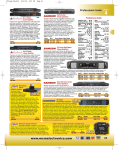
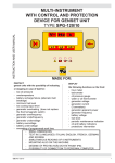
Electronic Systems Protection, Inc
8001 Knightdale Blvd.
Suite 121
Knightdale NC 27545
© 2014 SurgeX / Electronic Systems Protection, Inc.
SX1200 Series
INSTALLATION INSTRUCTIONS
surgex.com
IMPORTANT SAFETY INSTRUCTIONS
WARNING: TO REDUCE THE RISK OF FIRE OR
ELECTRIC SHOCK, DO NOT EXPOSE THIS APPLIANCE
TO RAIN OR MOISTURE.
WARNING: CONNECT ONLY TO MAINS SOCKET
WITH PROTECTIVE EARTHING CONNECTION.
The lightning flash with arrowhead symbol,
within an equilateral triangle is intended to
alert the user to the presence of uninsulated
d a n g e r o u s v o l t a g e w i t h i n t h e p r o d u c t ’s
enclosure that may be of sufficient magnitude
to constitute a risk of electric shock to persons.
The exclamation point within an equilateral
triangle is intended to alert the user to
the presence of important operating and
maintenance (servicing) instructions in the
literature accompanying the appliance.
CAUTION
1. Please read and retain these safety instructions.
2. Heed all warnings in the operating instructions and on the appliance.
3. Do not use this apparatus near water or moisture.
4. Clean only with a dry cloth.
5. Install in a good quality 19" equipment rack
6. Do not install near sources of heat such as radiators, heat registers, stoves or other apparatus that produce heat
(such as amplifiers).
7. Refer all servicing to authorised personnel.
8. Servicing is required when the apparatus has been damaged in any way including: Impact damage, power cord/
supply damage, liquid spillages, small objects falling into the unit or exposure to moisture. In addition please refer
to authorised service personnel if the apparatus is not operating normally.
9. To completely disconnect this equipment from the AC mains disconnect the power plug from the AC receptacle.
10. To prevent fire never place the unit near any naked flame such as a candle.
11. This is a CLASS 1 device and shall be connected to a mains socket with a protective earth connection.
12. Do not defeat the purpose of the polarized or grounding type plug. A polarized plug has two blades with one wider
than the other. A grounding type plug has two blades and a third grounding prong. The wide blade or the third
prong are there for your safety. If the plug does not fit into your outlet, consult an electrician for replacement of the
obsolete outlet.
Management of WEEE (Waste Electrical and Electronic Equipment) Applicable in member states of the
European Union and other European countries with individual nation policies on the management of
WEEE) The symbol on the product or its packaging indicates that this product may not be treated as
regular household waste. It should be returned to the retailer where the product was purchased or local
collection systems should be used to ensure environmentally safe recycling.
© 2014 SurgeX / Electronic Systems Protection, Inc.
surgex.com
SX1200
SX1200
Series
SURGE ELIMINATOR & POWER CONDITIONER
Installation Instructions:
table. Plug the equipment cords into the always-on and
switched receptacles as needed to power the equipment.
Caution:
The SurgeX ® 1200 series products permit a maximum
16A (SX1216 models), 15A (SX1215 models), 13A (SX1213
models) or 10A (SX1210 models) total output load with
a maximum 10A load per outlet. Please check and make
sure that each load connected to the unit does not exceed
10A. Also make sure that the total does not exceed your
mains receptacles current limit.
The always-on and courtesy receptacles (where fitted) provide
power as long as power is supplied to the SurgeX®. The eight
switched rear receptacles provide power only when the front
panel switch is on and, in the case of RTi products, when the
remote control input is also activated.
For safety please plug your SurgeX® unit into a fused
receptacle (T20AL 250v fuse recommended).
The SX1200 series have two, three or four indicator lights on
the front panel and a polarity indicator lamp on the rear panel:
SurgeX® Series Mode® Protection is Live-Neutral only, if
the polarity indicator is illuminated when connected to the
mains please replace the plug observing correct polarity.
Amber polarity light (Rear panel, all products): Indicates
that live and neutral are reversed and your SurgeX product will
not work as intended. If you are using an SX1216 (European
Cee7/7 connectivity) simply reverse the connection. If you are
using an SX1210, SX1213 or SX1215 consult an electrician to
correct and establish a proper polarity.
Mounting
The SurgeX® SX1200 series are designed to be installed in
a 19 inch equipment rack and require one unit (1-U) of rack
space. Remove the product from its packaging and slide it into
place in the rack being careful to feed the power cord into the
rack first and guide it so that it does not get caught or jammed
as the product is installed.
230 Volt Connections
Connect power to the unit by plugging the cord into a 230V
mains receptacle. The SX1200 series must be plugged into
the appropriate properly polarized receptacle.
Model
SX1210
SX1213
SX1215
Standard
AS3112
BS1363
BS546
Total Load
10A
13A
15A
SX1216
Cee7/7
16A
Receptacle
Australian style receptacle
British style receptacle
South African / Indian style
receptacle
European style receptacle
The SX1200 series have a total of 10 rear receptacles: eight
switched and two always on. The SX1200 series also feature
a front panel courtesy receptacle, which is always on. Each
receptacle is rated for a maximum load of 10 amps, but the
total load must not exceed the load specified in the above
© 2014 SurgeX / Electronic Systems Protection, Inc.
Indicator Lights
Red Power Light (All products): indicates that power is
supplied to the unit and the power switch is turned on.
Green Self-Test Light (All products): indicates that power is
supplied to the unit and the internal surge protection circuitry
is fully functional.
Orange Over/Under Voltage Protection Light (RTi & RLi
products): indicates that the mains voltage is below 190 volts
or above 280 volts.
Yellow Remote Light (RTi products): indicates that the
remote control is active and the rear switched receptacles are
on. (The power switch must also be on).
Lamp Connectors (RLi Only)
The RLi version has provision for two Task Lamps. Plug
the Lamps into the two three-pin XLR connectors on the
front panel and use the dimmer to set a suitable brightness.
Standard or HI brightness Lamps can be used. Each
connector can supply up to 5 Watts maximum. LED type
Lamps can be used with the RLi but the dimmer must be set
fully clockwise.
surgex.com
CAUTION: Do not repeatedly turn an RTi / RLi product
Remote Indicator LED
Remote Control (RTi Products Only)
Connecting the Remote LED is optional. An LED connected to
pins 4 and 5 will indicate when the switched receptacles are
on. 10mA of current is available at this output, but you must
use a series resistor if you are using your own LED. For
most LEDs a 1K resistor will provide suitable brightness. If you
need less brightness use a larger value of resistor, and if you
need more brightness use a smaller value of resistor.
on-off-on-off with a heavy load connected. The ICE ®
circuitry absorbs the inrush energy each time the unit is
turned on and may overheat if this is done repeatedly in
a short period of time. Wait one minute between repeated
turn-ons.
Remote control connections are wired to the green 7-pin
plug-in Phoenix terminal block on the rear of the unit next to
the power cord. The terminal block is shipped with a jumper
wire between pins 1 & 2 so that the unit can be used without
a remote control connection. If you will be using a remote
control you will first need to remove this jumper wire. You can
unplug the terminal block to make connections and after you
have made the connections to the terminal block, plug it back
into the connector on the rear of the unit. Never solder (tin)
wires before inserting into a terminal block – solder cold flows
and you will eventually have loose connections!
The connections are as follows:
Pin 1 -- Contact Closure
Pin 2 -- Contact Closure / Applied Voltage +
Pin 3 -- Applied Voltage Pin 4 -- Remote LED +
Pin 5 -- Remote LED Pin 6 -- Aux Relay Contact
Pin 7 -- Aux Relay Contact
Control Connections
•
•
Connect the LED positive wire to Pin 4
Connect the LED negative wire to Pin 5
Auxiliary Relay Contacts
The auxiliary relay contacts, pins 6 & 7, provide a way to
cascade units or to provide confirmation feedback to a central
controller. When the switched receptacles are on, the aux
relay contacts are closed. There is a 1 second delay before
the aux relay closes which gives time for the SurgeX® Inrush
Current Elimination (ICE®) circuit to operate. This short delay
in combination with the SurgeX® ICE® makes it unnecessary
to sequence the power to several large loads (such as
amplifiers) because of inrush current. SurgeX® RTi products,
when cascaded, can turn on a bank of large amplifiers with
no inrush current, and therefore no risk of blowing a circuit
breaker.
To cascade two or more RTi products, connect the aux relay
contacts of one unit to the contact closure input of the next
unit. To provide confirmation feedback, connect the aux relay
contacts to an input on the central controller.
The relay contacts are rated for 1 amp at 30 V DC.
Control of the switched receptacles can be accomplished by
using a switch (contact closure), another SurgeX® RTi product,
or by an applied voltage (5 to 30 volts DC). When using a
switch, choose a switch with gold contacts for the best longterm reliability.
Connections are made to terminal block pins 1, 2 & 3 as
follows:
•
Connect switch contacts, a contact closure, or SurgeX®
control to pins 1 and 2.
Or:
• Connect an applied DC voltage to pins 2 and 3. The
positive must be connected to pin 2 and the negative
must be connected to pin 3.
© 2014 SurgeX / Electronic Systems Protection, Inc.
surgex.com
Characteristics:
Part Number
Nominal line to neutral voltage U0 (V)
Max.Cont. Operating Voltage Uc (V)
Voltage protective level Up (V)
Max. shorted current. (Isc)
Open circuit voltage (Uoc)
TOV characteristic
(UT)
Degree of protection (IP)
Disconnection Device
Applicable Power Supply System
Polarity indicator (near the supply cord)
Location
Number of ports
Voltage regulation
Operation temperature and humidity:
Importer: XXXX; Address:XXXX.
SurgeX® Series Mode® Protection
230V
275VAC
1KV
3KA
6KV
TOV withstand , tT = 5s, UT = 335V;
IP20
Plug
TN TT IT
Illuminated: wrong; Off: correct
Indoor
Two
≤ 1%
-40 - +35°C, 30-90%
Made in China
Limited Ten Year Product Warranty
AS3112, BS1363, BS546, and CEE7/7
International Products
For a period of 10 years from the date of your purchase of any SurgeX international product, SurgeX warrants the product
(AS3112, BS1363, BS546, CEE7/7 standard) against defects in materials used by SurgeX or workmanship performed by
SurgeX (a "Covered Product"). SurgeX’s obligations with respect to a Covered Product are to provide, at no charge, all labor
and parts (either new or rebuilt, as determined in SurgeX’s sole discretion) necessary for the repair of the Covered Product. If
SurgeX, in its sole discretion, determines that a Covered Product is not repairable, SurgeX will replace the Covered Product with
a product of like kind, quality and functionality. In order to obtain the services under this Limited Warranty, you are responsible
for delivering the Covered Product, at your sole cost, to a SurgeX authorized distributor, and for providing the SurgeX authorized
distributor with a copy of the dealer's dated bill of sale as evidence of the date of purchase of the product.
THIS LIMITED WARRANTY IS THE SOLE AND EXCLUSIVE WARRANTY MADE BY SURGEX WITH RESPECT TO
THE PRODUCT. ALL IMPLIED WARRANTIES WITH RESPECT TO THE PRODUCT INCLUDING, BUT NOT LIMITED
TO, IMPLIED WARRANTIES OF MERCHANTABILITY OR FITNESS FOR A PARTICULAR PURPOSE OR IMPLIED
WARRANTIES ARISING OUT OF COURSE OF DEALING OR USAGE OF TRADE ARE HEREBY EXPRESSLY DISCLAIMED
AND EXCLUDED.
This Limited Warranty does not apply to any product which is defective due to any causes beyond SurgeX’s control such as
negligence, abuse, misuse, acts of god, modifications to the product or third party repair of the product.
THE LIABILITY OF SURGEX (IF ANY) AND YOUR SOLE AND EXCLUSIVE REMEDY FOR ANY ALLEGEDLY DEFECTIVE
SURGEX INTERNATIONAL PRODUCT SHALL BE LIMITED TO REPAIR OR REPLACEMENT OF THE PRODUCT IN
ACCORDANCE WITH THE TERMS AND CONDITIONS OF THIS LIMITED WARRANTY. IN NO EVENT WILL SURGEX BE
LIABLE FOR ANY SPECIAL, INDIRECT, INCIDENTAL OR CONSEQUENTIAL DAMAGES.
© 2014 SurgeX / Electronic Systems Protection, Inc.
surgex.com