1
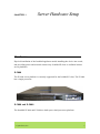
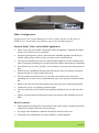
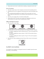
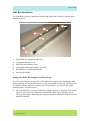
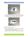
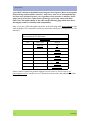
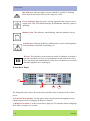
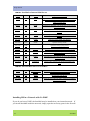
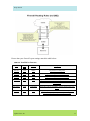
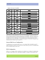
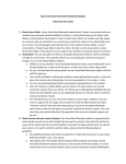
OCTOBER 2006
IronMail Setup Guide
Product Version: E-class
©2006 CipherTrust, Inc. CipherTrust and the CipherTrust logo are registered trademarks of
CipherTrust, Inc. All other trademarks are the property of their respective owners. All rights
reserved.
ii
IronMail
IronMail Setup Guide
Product Version E-class
Table of Contents
Server Hardware Setup .........................................................................1
Hardware ......................................................................................................... 1
E-2000 ...................................................................................................... 1
E-3000 and E-5000 .................................................................................. 1
Other Configuration ................................................................................. 2
General Safety Notes on IronMail Appliances ........................................ 2
IronMail E-class Installation .................................................................... 3
Slide Rail Installation ............................................................................... 5
Uninterruptible Power Supply ........................................................................ 7
Attaching Keyboard, Mouse, and Monitor ..................................................... 9
Server Power, Controls, and Indicators .......................................................... 9
IronMail E-class Power, Controls and Indicators .................................... 9
Network Configuration .......................................................................13
Network Connectivity ................................................................................... 13
Network Firewall Configuration ............................................................ 13
Internal Mail Server Configuration ........................................................ 18
DNS Configuration ................................................................................ 18
Setting Up CipherTrust IronMail ........................................................21
Configuring IronMail .................................................................................... 22
Best Practices Configuration ..............................................................35
SmartStart ..................................................................................................... 35
Using SmartStart .................................................................................... 36
Screen 1: Network Connectivity ............................................................ 39
Screen 2: Software Updates ................................................................... 39
Screen 3: Pre-Configuration ................................................................... 40
Screen 4: Threat Response Updates ....................................................... 41
iii
Screen 5: Virus Updates ......................................................................... 42
Screen 6: SMTP Route Setup ................................................................. 44
Screen 7: Internal Server List ................................................................. 44
Screen 8: Allow Relay ........................................................................... 45
Screen 9: Report Setup ........................................................................... 46
Screen 10: Alerts Setup .......................................................................... 47
Screen 11: Add Accounts ....................................................................... 48
Screen 12: Change the Admin Password ............................................... 48
Screen 13: Finishing SmartStart ............................................................. 49
iv
IronMail
CHAPTER 1
Server Hardware Setup
Hardware
Physical installation of the IronMail appliance entails installing the device into a rack,
and providing power and network connectivity. IronMail E-class is available in three
server platforms.
E-2000
The E-2000 server platform is currently supported for the IronMail E-class. The E-2000
has a single processor.
E-3000 and E-5000
The IronMail E-3000 and E-5000 are built upon a dual-processor platform.
CipherTrust, Inc.
1
Setup Guide
Other Configuration
Configuration of the Central Managment Console (CMC) and Secure Web Delivery
(SWD) servers should follow the hardware setup of the IronMail appliance.
General Safety Notes on IronMail Appliances
•
There are no user-serviceable components inside the appliance. Opening IronMail’s
chassis will void the service agreement.
•
Adequate spacing above, below, and behind the IronMail appliance should be provided to allow proper airflow, and to prevent excessive heat build-up.
•
Use only the mounting kits provided with IronMail appliances when installing IronMail, as improper mounting may result in hardware failure and hazardous conditions.
•
Do not block any air vents; usually 15 cm (6 inches) of air space provides proper airflow.
•
Plan the device installation starting from the bottom of the rack cabinet and install
the heaviest device in the bottom of the rack.
•
Do not extend more than one device out of the rack cabinet at the same time—
extending two or more devices simultaneously may cause the rack to become unstable.
•
•
•
Remove the rack doors and side panels to provide easier access during installation
•
Follow accepted electrical and general safety precautions when installing any IronMail.
Connect the server to a properly grounded outlet.
Do not overload the power outlet when installing multiple devices in the rack cabinet.
Rack Precautions
•
Ensure that the leveling jacks on the bottom of the rack are fully extended to the floor
with the full weight of the rack resting on them.
•
•
In a single rack installation, stabilizers should be attached to the rack.
In multiple rack installations, the racks should be coupled together.
2
IronMail
Setup Guide
•
Always make sure the rack is stable before extending a component from the rack.
Server Precautions
•
•
Determine the placement of each component in the rack before installing the rails.
•
Use a regulating uninterruptible power supply (UPS) to protect the server from
power surges and voltage spikes, and to keep the system operating in case of a power
failure.
•
•
Allow the power supply units to cool before touching them.
Install the heaviest server components on the bottom of the rack first, and then work
up.
Always keep the rack's front door and all panels and components on the servers
closed when not servicing in order to maintain proper cooling.
Lifting and Weight Precautions
•
Use safe practices when lifting.
•
For lifting objects with the following weights use the designated number of people:
•
•
For objects weighing more than or equal to18 kg (39.7 lb) use two people to lift
the object.
•
For objects weighing more than or equal to 32 kg (70.5 lb) use three people to
lift the object.
•
For objects weighing more than or equal to 55 kg (121.2 lb) use four people to
lift the object.
Do on place any object weighing more than 50 kg (110 lb) on top of rack-mounted
devices.
IronMail E-class Installation
The IronMail E-class appliances are designed to mount in a standard 4-post data center
rack having a 19-inch opening.
CipherTrust, Inc.
3
Setup Guide
Tools required:
A Phillips #2 screwdriver is the only tool required.
Contents of the E-class mounting kit:
4
•
Power cord
•
Network Connection cord
•
Bezel mounts with screws
•
Mounting screws
IronMail
Setup Guide
Slide Rail Installation
The Slide Rails consist of individual left and right slide rails. Details are shown in the
illustration below.
5
4
6
3
2
1
1.
Front Multi-Pin Adapter and Bracket
2.
Component Release Lever
3.
Slide Extension Release Lever
4.
Component Mounting Channel (3 per rail)
5.
Rear Multi-Pin Adapter and Bracket
6.
Anti-Sag Bar Slider
Setting the Multi-Pin Adapters for Rack Type
The 10-32 threaded hole in the center of the Multi-Pin Adapter is for securing the rails
during shipping, and for the attachment of front panel blanks (if desired). The Slide rails
are shipped with the Multi-Pin Adapters set for square holes. If your rack has square
mounting holes, skip this section.
1.
On each Slide Rail, reverse the Multi-Pin Adapter position to match the rack mounting hole type if necessary. Remove the Multi-Pin Adapter by rotating the Swivel
Lock up, pressing the mounting pins together, and then pulling the adapter from the
Multi-Pin Bracket.
CipherTrust, Inc.
5
Setup Guide
2.
Install the Multi-Pin Adapter by pressing the pins together while inserting the adapter
into the bracket. The Multi-Pin Adapter must be fully locked in the bracket. Ensure
both mounting pins on the Multi-Pin Adapter are fully engaged in the Multi-Pin
Bracket, then lock the Multi-Pin Adapter in place using the Swivel Lock.
3.
Repeat these steps for both ends of each Slide Rail.
Installing the Slide Rails into the Rack
At all four rack uprights, determine the vertical position in the rack where the Slide
Rails are to be installed. The top-most mounting hole for a particular rack unit (RU)
mounting position is typically indicated by a mark or hole.
1.
CAUTION: If Slide Rails are mounted in holes which are not vertically aligned
(level) from front to back, the Slide Rail may be damaged and mounting will not be
secure.
6
IronMail
Setup Guide
2.
Noting the holes determined in the previous step, align the left Slide Rail with its
mounting holes.
3.
Hold the Slide Rail in the desired rack mounting position. At the rear of the Slide
Rail, press the Multi-Pin Adapter mounting pins together and insert the Slide Rail
into the rack.
4.
Ensuring you have selected the proper mounting holes on the rack upright, repeat the
above step at the Slide Rail’s front mounting position. Ensure the Slide Rail is level.
5.
Extend the Slide Rail to its fully extended (locked) position. Press the Slide Rail
Extension Release Levers to release the lock. Move the Slide Rail in and out through
its entire range of motion to ensure it does not bind. If binding occurs, recheck the
mounting positions.
6.
Repeat steps 2 through 5 for the right Slide Rail, being certain that it is parallel and
level with the left Slide Rail.
Installing the Component into the Slide Rails
1.
Extend both Slide Rails to into their fully extended (locked) positions.
2.
Align the mounting studs withthe Component Mounting Channels on the Slide Rails.
3.
Carefully place the component’s mounting studs in the Component Mounting Channels on the Slide Rails. Allow the component mounting studs to fully seat in the
Component Mounting Channels. The Component Release Levers (one on each rail)
pivot out of the way and then back into place when the studs are fully engaged in the
mounting channels. Ensure the Component Release Levers are in the locked position.
4.
Press and hold both the left and right Slide Extension Release Levers and slowly
slide the component and Slide Rails into the fully retracted position.
Uninterruptible Power Supply
IronMail should only be used in conjunction with an Uninterruptible Power Supply
(UPS). While many UPS devices are suitable for providing power, not all are able to
CipherTrust, Inc.
7
Setup Guide
“gracefully” shut down IronMail in an emergency loss of power. Many are incapable
of interfacing with IronMail’s software. And worse, some are so incompatible they
will shut down IronMail on their own, regardless of the presence or absence of adequate power! Therefore, CipherTrust encourages you to only connect the data
cables for UPS models shown on the table on the following page which have been
thoroughly tested for reliability and compatibility.
Note: If you use a UPS other than one shown in the following table, do not attach a data
cable from the UPS to IronMail’s serial port (when the serial port is configured as a UPS
interface).
Recommended UPS Hardware
IronMail E-class
APC
Matrix-UPS
MX3000
Smart-UPS
700
700 XL
700 RM 2U
1000 XL
1000 RM 2U
1400
1400 RM 2U
1400 RM 3U XL
Please contact CipherTrust product support at 678-867-2999 or send an email to [email protected] to confirm if your UPS has been tested since the publication of this
Setup Guide.
8
IronMail
Setup Guide
Attaching Keyboard, Mouse, and Monitor
IronMail accepts the connection of keyboard, mouse, and monitor allowing you to
connect to the appliance directly (in addition to, or in lieu of connecting through
your local area network). Attach a monitor to the VGA port on the back of the
appliance. Attach keyboard to the bottom PS-2 port on the back of the appliance.
(The mouse and keyboard must be connected to the appliance before power is
turned on.)
You only have access to the command line interface when connected directly to the appliance—you do not have access to the graphical, browser-based Web Administration interface. The command line interface allows you to perform some of the functionality
available in the Web Administration GUI, but more importantly, it allows you to restore
the appliance to its factory default settings.
Once the appliance is powered up, the monitor will display a logon prompt. Enter the
same user name and password you use to connect to the Web Administration graphical
user interface. Refer to the chapter on “Command Line Interface” in the User Manual for
instructions on using the available commands.
Server Power, Controls, and Indicators
IronMail E-class Power, Controls and Indicators
This section identifies the controls and indicators on the front and rear of the IronMail Eclass servers. It also describes the power features of the server.
Control Panel LEDs
This section identifies the indicator LEDs on the front of the E-class appliance.
CipherTrust, Inc.
9
Setup Guide
NIC Indicator. Indicator lights exist for both NIC1 and NIC2. Flashing
LEDs indicate network activity on the respective LANs.
Power Indicator. Indicates power is being supplied to the system’s power
supply units. This LED should normally be illuminated when the system is
operating.
Database Icon. This indicator, when flashing, indicates database activity.
Caution Icon. Indicates problems, malfunctions or errors in the appliance.
Such problems can include overheating, etc.
ID
ID Icon. This indicator can be turned on (steady or flashing) to identify a
specific unit when you have several appliances in the same rack or location. This allows the Administrator or any service technician to see which
IronMail appliance he is working on.
E-class Rear Panel
1
2
3
4
The illustration above shows he connections available on the rear panel of the E-2000
server.
1. Keyboard Port (purple). Use this port to plug a keyboard into the appliance when
configuring the server or using the E-2000 as a console.
2. Monitor Port (blue). Use this connection to plug in a VGA monitor when configurign
the E-2000 or using it as a console.
10
IronMail
Setup Guide
3. Mail Traffic Ethernet Port. Connect to the network using the port to the left, labeled
LAN1.
4. Out of Band Management Port. For out of band management, connect to the other
Ethernet port, labeled LAN2.
Power (black). A black power connection (not shown) is on the right side of the server.
CipherTrust, Inc.
11
Setup Guide
12
IronMail
CHAPTER 2
Network Configuration
Network Connectivity
Your network administrator must assign an IP address, subnet mask, and host name for
the IronMail appliance. (A host name “yourname” and domain name “yourdomain.com”
results in the fully qualified domain name (FQDN) “yourname.yourdomain.com.”) The
first time you connect to IronMail, you will be required to enter this and other information
into its configuration database. Establishing network connectivity may require the assistance of your network administrator.
Based on your company’s network design, IronMail may be connected to the corporate
network either in a De-Militarized Zone (DMZ) or on the internal LAN. Once the physical connection has been established, some configuration of the network firewall and
Domain Name Service (DNS) will be required.
Network Firewall Configuration
There are three main styles of firewalls: packet filter-types (routers with ACLs), application proxy-types (e.g., Raptor and TIS Gauntlet), and stateful inspection-types (e.g.,
CheckPoint and Cisco PIX). It is important to understand most application proxy firewalls do not support SMTP over SSL (i.e. the SMTPS protocol). If your firewall is an
application proxy-type that does not support SSL, IronMail will not be able to encrypt
your mail. Both packet filter and stateful inspection firewalls, however, fully support
SMTP over SSL if they are configured correctly.
CipherTrust, Inc.
13
Setup Guide
It is recommended that you place IronMail in a DMZ if your network supports it. If so,
you must create rules to allow the protocols for the following:
•
•
•
•
IronMail to Internet
Internet to IronMail
IronMail to the internal mail server
Internal mail server to Ironmail
Installing IronMail in a DMZ
There should be no open protocols from outside to inside (bypassing IronMail) when
using a DMZ configuration.
14
IronMail
Setup Guide
The following tables describes the ports you must open in your firewall to allow IronMail
to function:
TABLE 1. IronMail
to Internet
Port
TCP/
UDP
Protocol
Description
Port 25
TCP
SMTP
Required for mail delivery
Port 53
TCP/
UDP
DNS
Optional for an IronMail/CMC (if your DNS is outside
the network, you must open the port allowing IronMail/
CMC to connect to it).
Port 123
TCP
NTP
Required if using Network Time Protocol
Port 6277
UDP
SLS
Required if you wish to enable Statistical Lookup Service
(SLS) lookup as part of your anti-spam strategy.
Port 20022
TCP
CipherTrust
Required in order for IronMail to request software/antivirus updates
TABLE 2. Internet
to IronMail
Port
TCP/
UDP
Protocol
Description
Port 25
TCP
SMTP
Required for mail delivery
Port 80
TCP
HTTP
Optional for WebMail (secure HTTPS on port 443 is preferred)
Port 110
TCP
POP3
Optional (secure POP3 on port 995 is preferred)
Port 143
TCP
IMAP4
Optional (secure IMAP4 on port 993 is preferred)
Port 443
TCP
HTTPS
Optional for WebMail (for secure HTTPS proxying)
Port 465
TCP
SMTPS
Optional for secure incoming messages
Port 993
TCP
IMAP4S
Optional (this is the preferred port to securely retrieve
mail via IMAP4)
Port 995
TCP
POP3S
Optional (this is the preferred port to securely retrieve
mail via POP3S)
Port 20022
TCP
CipherTrust
Required (allows CipherTrust to connect to your IronMail for technical support
TABLE 3. IronMail
to Internal Mail Server
Port 21
TCP
FTP
Optional if using FTP
Port 22
TCP
SCP
Optional if using SCP.
CipherTrust, Inc.
15
Setup Guide
TABLE 3. IronMail
Port 25
to Internal Mail Server
SMTP
Required for mail delivery
Port 53
UDP
DNS
Optional for an IronMail/CMC (if your DNS is inside the
network, you must open the port allowing IronMail/
CMC to connect to it).
Port 80
TCP
HTTP
Optional for WebMail (you should open secure port 443
for HTTPS instead)
Port 110
TCP
POP3
Optional (you should open port 995 for secure POP3S
instead)
Port 143
TCP
IMAP4
Optional (you should open secure port 993 for IMAP4S
instead)
Port 162
TCP
SNMP
Optional if using SNMP Trap Manager
Port 389
TCP
LDAP
Optional if using LDAP.
Port 514
UDP
Port 443
TCP
HTTPS
Optional for WebMail (for secure HTTPS proxying)
Port 993
TCP
IMAP4S
Optional (this is the preferred port to securely retrieve
mail via IMAP4S)
Port 995
TCP
POP3S
Optional (this is the preferred port to securely retrieve
mail via POP3S)
Port 20022
TCP
CipherTrust
Allows CMC connection to managed IronMail appliance.
TABLE 4. Internal
Optional if using Syslog Server
Mail Server to IronMail
Port 22
TCP
Command Line
Interface
Optional (only if you want to access the command line
interface from inside the network)
Port 25
TCP
SMTP
Required for mail delivery
Port 10443
TCP
HTTPS
Required (this is the port used to connect to IronMail’s
WebAdmin interface)
Installing IM in a Network with No DMZ
If you do not have a DMZ, the IronMail may be installed on your internal network. If
you install IronMail inside the network, simply open the necessary ports in the firewall.
16
IronMail
Setup Guide
Ensure that your firewall’s port settings match the table below:
TABLE 5. IronMail
to Internet
Port
TCP/
UDP
Protocol
Description
Port 25
TCP
SMTP
Required for sending mail
Port 123
TCP
NTP
Required if using Network Time Protocol
Port 123
UDP
NTP
Required if using Network Time Protocol
Port 53
UDP
DNS
Optional for an IronMail/CMC (if your DNS is outside the
network, you must open the port allowing IronMail/CMC to
connect to it).
Port 20022
TCP
CipherTrust
Required in order for IronMail to request software/anti-virus
updates
Port 6277
UDP
SLS
Required if you wish to enable Statistical Lookup Service
(SLS) lookup as part of your anti-spam strategy.
CipherTrust, Inc.
17
Setup Guide
TABLE 6. Internet
to IronMail
Port 25
TCP
SMTP /
SMTPS
Required
Port 80
TCP
HTTP
Optional (you should open secure port 443 for HTTPS
instead)
Port 110
TCP
POP3
Optional (you should open port 995 for secure POP3S
instead)
Port 143
TCP
IMAP4
Optional (you should open secure port 993 for IMAP4S
instead)
Port 443
TCP
HTTPS
Optional for IronWebMail (for secure HTTPS proxying)
Port 465
TCP
SMTPS
Optional (this is the preferred port to securely send mail)
Port 993
TCP
IMAP4S
Optional (this is the preferred port to securely retrieve mail
via IMAP4)
Port 995
TCP
POP3S
Optional (this is the preferred port to securely retrieve mail
via POP3)
Port 6277
UDP
SLS
Required for IronMail’s Statistical Lookup Service spamblocking tool.
Port 10443
TCP
HTTPS
Required (this is the port used to connect to IronMail’s
WebAdmin interface)
Port 20022
TCP
CipherTrust
Optional (allows CipherTrust to connect to your IronMail for
Technical Support)
Most mail servers use only ports 25, 110, and 143 for sending and retrieving email. However, messages transmitted through these ports are unencrypted—attackers can read or
intercept email sent this way. We recommend that you open the secure ports instead: 995
for POP3S and 993 for IMAP4S to force external users to retrieve their mail via SSL.
(IronMail also provides the ability to send mail encrypted via TLS/SGL (Transport Layer
Security/Secure Sockets Layer) on port 25.)
Internal Mail Server Configuration
Configuration of your internal mail servers is very simple. Make IronMail the only IP
address allowed to connect to your mail server, and re-direct your servers’ outbound mail
flow to IronMail using a static route.
DNS Configuration
DNS is a very complex subject, and there is no standard way in which it is implemented.
In addition to the DNS server’s MX (Mail Exchange), A (address), PTR (pointer) and
18
IronMail
Setup Guide
other records, some networks use Network Address Tables (NAT) to map servers internally. However you implement DNS, you must at least do the following: The MX record
pointing to the IronMail must have a lower preference number (i.e. higher priority) than
the other MX records for the domain. This allows all mail addressed to your domain to be
routed to the IronMail appliance, and allows all other servers to perform DNS lookups
and reverse lookups on IronMail.
Follow these configuration steps:
Step 1.
Create the A record for the IronMail. The A records provide the forward mapping of hostnames to IP addresses.
Step 2.
Create the PTR record for the IronMail. PTR records provide the reverse mapping of IP addresses.
Step 3.
Create the MX record for each domain for which the IronMail will relay email.
Create the MX record number than the existing MX records.
Note: Spammers have begun targeting secondary MXs for delivery of spam
because often the anti-spam features are not as robust as the primary MX.
You can check whether reverse lookup is working using the “ping” command, with the “a” switch. Pinging an IP address with that switch will do a reverse lookup, and display the
resolved name:
C:\>ping -a 63.168.166.5
Pinging servername.yourdomain.com [63.168.166.5] with 32 bytes of data:
Reply from 63.168.166.5: bytes=32 time=731ms TTL=242
Reply from 63.168.166.5: bytes=32 time=1081ms TTL=242
Reply from 63.168.166.5: bytes=32 time=1052ms TTL=242
Reply from 63.168.166.5: bytes=32 time=611ms TTL=242
CipherTrust, Inc.
19
Setup Guide
20
IronMail
Setup Guide
CHAPTER 3
Setting Up CipherTrust
IronMail
The initial setup for IronMail includes at least two major components, and possibly a
third. The Installer or Administrator must set up the basic IronMail appliance to allow its
further configuration after the basic initialization is completed; they must also perform
essential setup for connectivity to the internet and to the mail network. The third component is necessary only if the IronMail appliance is being set up as a Centralized Management Console (CMC).
Setup results in only the most basic configuration of IronMail. Once all initial setup is
complete, the Administrator will perform the detailed configuration that prepares IronMail to protect the specific network.
In this chapter:
In this chapter, you will find information about the following topics:
•
•
Configuring IronMaill
Initial Configuration Wizard
CipherTrust, Inc.
21
Setup Guide
Configuring IronMail
Preliminary Information
IronMail—whether intended as a stand-alone appliance or as a Centralized Management
Console—uses a simple wizard to set the initial values required for it to become minimally functional. Before you run the wizard, obtain the information requested in the form
below. Your network administrator should be able to assist you in determining the network information. (A copy of this Information Gathering Form appears at the back of the
Setup Guide so it may be removed for easy information gathering.)
Step 1.
Have on hand the License Key that was e-mailed to you for the IronMail appliance. The License Key contains information that determines whether this appliance is a Centralized Management Console for enterprise environments or a
stand-alone IronMail.
Step 2.
Create a host name for this appliance.
Step 3.
Determine the domain name to which this appliance belongs.
Step 4.
Assign an IP address for this appliance.
Step 5.
Determine the Subnet Mask for this appliance.
Step 6.
Specify the Default Router the appliance will use.
Step 7.
Specify the IP Address of at least one of your DNS Servers (This appliance must
be able to connect to it.)
Step 8.
Provide the fully qualified domain names of up to three Network Time Protocol
servers. (IronMail identifies three servers by default.)
Step 9.
Specify the appliance’s time zone by selecting from the pick list the city nearest
the appliance. (The selected city must be in the same time zone as IronMail.)
Step 10.
For “stand-alone” IronMail only! — Specify the fully qualified domain name of
your default mail server. (If you have dedicated servers handling incoming and
outgoing mail, or other services, select one to enter during the wizard setup—the
remaining servers will be configured later.) This information is not necessary for
configuring a Centralized Management Console.
Step 11.
Specify the IP address of the default mail server you identified above.
Step 12.
Specify your default email domain.
Step 13.
Determine if you want IronMail to use secure POP3 or IMAP 4 with your internal server. (Your internal server must have a Security Certificate installed on it
for secure POP3 or IMAP4 to be implemented.).
Verify this information with your Network Administrator prior to running the appliance’s
Initial Configuration Wizard.
22
IronMail
Setup Guide
Initial Configuration Wizard
IronMail ships with a pre-installed, albeit unsigned, Security Certificate. IronMail only
allows administrative sessions with it over a secure SSL (https) connection, for which a
Security Certificate is required. The default Security Certificate is adequate for creating
these secure connections from your browser to the IronMail appliance, but is not adequate
for providing SSL security for your email infrastructure. Until you install a valid Security
Certificate from a Certificate Authority, your browser will display a Security Alert each
time you logon to the appliance. Clicking Yes at the prompt allows you to proceed.
You must connect to the appliance to enter some preliminary values in an Initial Configuration Wizard in order to make the appliance initially functional. Use a client workstation
(any Windows PC) as IronMail’s “front end.” There are two ways you can connect to the
appliance:
•
Use a network “cross-over” cable to physically connect a PC workstation to IronMail. (The cable plugs into the network port on each device.)
•
Install IronMail in your existing network, but set a PC workstation’s netmask to
match IronMail’s default IP address and netmask.
For either type of connection, the client workstation must temporarily change its IP
address and netmask to match IronMail’s default values (IP Address: 192.168.0.254, Netmask: 255.255.255.0). That is, change your workstation IP address to 192.168.0.xxx, and
the netmask to 255.255.255.0 (where xxx is any number between 0-253).
1.
Launch Internet Explorer on the client workstation and navigate to IronMail’s builtin default IP address:
https://192.168.0.254
You must add the letter “s” after “http.”
The opening screen for the Installation Wizard displays. Click Next to begin the
installation process.
CipherTrust, Inc.
23
Setup Guide
Step 2.
The first screen to appear is the Master Sale and License Agreement. After you
have read the agreement, click Accept or Decline. If you choose to Decline, the
installation wizard will close and the appliance will not run. If you choose
Accept, the wizard proceeds to the next step.
Step 3.
The next screen that opens displays the Support Services Agreement. After you
have read the agreement, click Accept or Decline. If you choose to Decline, the
24
IronMail
Setup Guide
installation wizard will close and the appliance will not run. If you choose
Accept, the wizard proceeds to the next step.
Step 4.
Select the language you wish to use for this installation of IronMail by choosing
the name of the language from the pick list. Select the character set for this IronMail from the second list.
Click Next.
Step 5.
Copy the text file containing the License Key for the appliance, and paste the
key into the input field on the next screen.
You must include all of the beginning and ending lines that appear with the License
Key, as shown:
CipherTrust, Inc.
25
Setup Guide
"======Begin CipherTrust License======" and "======End CipherTrust License======."
After pasting in the key, click Next.
Step 6.
Enter the host name for the appliance, created by your Network Administrator.
The host name is the text preceding the domain name. In the example "servername.yourdomain.com" "servername" is the host name, and "yourdomain.com"
is the domain name.
Click Next.
Step 7.
26
Enter the domain name for the domain to which the appliance will belong (e.g.,
"yourdomain.com").
IronMail
Setup Guide
Click Next.
Step 8.
Enter the IP address assigned by your Network Administrator for this appliance.
Click Next.
Step 9.
Enter the subnet mask for this IronMail, as provided by your Network Administrator.
CipherTrust, Inc.
27
Setup Guide
Click Next.
Step 10.
Enter the IP address for the Default Router for this appliance. The router address
is provided by the Network Administrator.
Click Next.
Step 11.
28
Enter the IP address for at least one of your DNS Servers (you may have up to
three). The DNS server will be used as a client for this IronMail.
IronMail
Setup Guide
Click Next.
Step 12.
Enter the IP address or the fully qualified domain name for up to three Network
Time Protocol (NTP) servers, as provided by the Network Administrator.
Click Next.
Step 13.
Specify the appliance's time zone by selecting from the pick list your own location or city, or a location/city that is in the same time zone.
CipherTrust, Inc.
29
Setup Guide
Click Next.
Step 14.
If you are configuring a stand-alone IronMail appliance, you must enter information about your default email server. If you have more than one email server,
enter only the information about the default server. You can configure additional
servers after you complete the Installation Wizard.
If you are configuring a Centralized Management Console, you do not have to provide information about internal mail servers. Skip this step by clicking Next, and
proceed to verifying your information.
Step 15.
30
Verify that the information you have provided is correct. You can use the Back
buttons to return to previous steps and make corrections, should you detect
IronMail
Setup Guide
errors. You may want to print this screen for your records once you have verified
the information.
If you inadvertently enter the IP address incorrectly and fail to print this page showing the appliance's dot-decimal number, you will be unable to log onto IronMail
when you later browse to what you thought was the correct address. Log onto IronMail via attached keyboard and command line interface to reset the appliance to its
default factory settings.
Click Finish after the information has been verified.
CAUTION. Do not press Enter a second time or click the Refresh icon. This can cause
problems with program integrity.
IronMail will automatically restart. The following message will display.
CipherTrust, Inc.
31
Setup Guide
When the restart process has had time to finish (wait at least three minutes), you may log
onto the appliance. Using your network browser, go to the IP address for the appliance
and log in.
IronMail's opening SmartStart screen will display, allowing you to continue with “best
practices” configuration.
32
IronMail
Setup Guide
Once a stand-alone IronMail is running, it is now acting as a proxy—incoming and outgoing mail will flow through IronMail to the email server you specified, and your exposure
to the outside world has been "hardened.” However, many of IronMail’s features have not
yet been enabled. Additional configuration is required as described in the remainder of
the User Manual.
CipherTrust, Inc.
33
Setup Guide
34
IronMail
Setup Guide
CHAPTER 4
Best Practices
Configuration
The concept of “Best Practices” configuration is derived from CipherTrust’s desire to
streamline the process of preparing the IronMail appliance for effective operation. SmartStart offers the means to do precisely that.
In this chapter
In this chapter, you will find information about the following topics:
•
SmartStart
• Using SmartStart
SmartStart
The purpose for SmartStart is to provide the Administrator the ability to install best practices IronMail configurations at the time of initial appliance installation and setup. It
allows the Administrator to install the current software upgrades, current Anti-Virus
upgrades, the Pre-Configuration package, the current Threat Response Update (TRU),
and several other common configuration entries.
The Administrator will complete the initial IronMail setup and installation as usual,
applying the standard Installation Wizard, as explained in the previous chapter and in the
IronMail Setup Guide. Then, at the Administrator’s first login, the initial SmartStart
screen displays.
CipherTrust, Inc.
35
Setup Guide
Unless the SmartStart installation is interrupted, subsequent logons will bypass SmartStart and take the user directly to the Dashboard, as discussed later in this manual.
Note. SmartStart functionality is available only to the Admin user account. For any other
user, the first login will open the Dashboard, IronMail’s regular opening screen.
Using SmartStart
Complete SmartStart installation requires completing the actions on 12 screens. It is
important for the Administrator to remember a few basic rules for navigating SmartStart.
Step 1.
You must select the specific SmartStart screen you wish to use by clicking the
screen’s link in the left menu. When you finish one screen, you can go to the
next by clicking its link.
Step 2.
If you need to leave the SmartStart Wizard before you have completed work
with all screens, you must leave by clicking Log Out at the top of the screen.
The next time you log in, IronMail will return you to the SmartStart screen from
which you logged out.
Step 3.
If you click Quit at the top of the screen, you will leave SmartStart, and will be
taken to the Dashboard screen. You will not automatically return to SmartStart
when you log in again.
Step 4.
Since some SmartStart steps need to be done in a specific order, please read the
instructions on each screen before you apply it.
The SmartStart Screen
As illustrated in the screen shot that follow, SmartStart screens are divided into three sections.
36
IronMail
Setup Guide
Left Side: Menu
The left side of the screen contains the menu listing
all 12 screens that may be used in SmartStart. You
will use this menu to select the portion of the wizard
you wish to apply.
You may click on any SmartStart screen link to open
it without regard for the order on the menu. However, some of the steps must be taken in order. Read
the screen instructions before you apply the screen.
Screen 1, the Network Connectivity check, is the
opening screen for SmartStart, since connectivity is
required to apply some of the other steps.
Upper Right: SmartStart information
The upper portion of the screen, as seen below,
extending across the screen except for the left menu
area, contains informative text about the screen you
are currently viewing. It may provide instructions
and other important information about the step you
are about to complete.
Lower Right: Configuration screens
The lower portion of all SmartStart screens, like the sample below, will contain the actual
IronMail configuration screens required to complete the specific step you are applying.
CipherTrust, Inc.
37
Setup Guide
IMPORTANT. The screen images that populate this portion of the SmartStart screen will
retain their own instruction text or help text.
Accessing SmartStart
To access SmartStart as part of the initial installation and setup of the IronMail, the
Administrator (Admin user account) simply logs into IronMail the first time.
Screen 1 of the SmartStart process opens.
38
IronMail
Setup Guide
Screen 1: Network Connectivity
The initial screen is designed to welcome the administrator, give basic SmartStart instruction, and test for Network Connectivity.
SmartStart Network Connectivity Check
This step tests the connectivity between your IronMail appliance and the CipherTrust
update infrastructure. Connectivity is required in order to use the SmartStart feature for
configuring your IronMail. You will use the update infrastructure in some of the following steps to update the version of software installed on your appliance, to download the
latest “best practices” Pre-Configuration or Threat Response Update packages, and to
install the most current Anti-Virus engine updates and virus signatures.
When you have tested your network connectivity, go to the next screen by clicking that
screen’s link in the left menu.
Screen 2: Software Updates
This step allows you to update the software on your IronMail appliance to the most current available version.
CipherTrust, Inc.
39
Setup Guide
SmartStart Software Updates
Network connectivity is required for this step. Depending upon the version of the IronMail software currently installed, this update may require more than one step and may
involve rebooting the appliance. If you need to install more than one release to get to the
most current version, use this screen to download and install each upgrade in order, one
upgrade at a time. If the appliance must be rebooted, you will be brought back to the
SmartStart feature when you log in again.
After you have set up configuration changes on the screen shown at the bottom of the
SmartStart page, use the commands on that screen to record your configuration. Then you
may proceed to the next screen by clicking that screen’s link in the left menu.
Screen 3: Pre-Configuration
This screen allows you to access and install the Pre-Configuration package for your version of the IronMail appliance software.
40
IronMail
Setup Guide
SmartStart Pre-Configuration Installation
This package sets general configuration parameters representing the current “best practices” in general administration for your IronMail appliance. Network connectivity is
required for this step.
IMPORTANT. You should install the Pre-Configuration package after upgrading to the
most recent version of the IronMail appliance software, and you should only install the
Pre-Configuration that is appropriate for your version of the software.
After you have set up the installation on the screen at the bottom of the SmartStart page,
use the commands on that screen to record your configuration. Then you may proceed to
the next screen by clicking that screen’s link in the left menu.
Screen 4: Threat Response Updates
This screen allows you to access and install the latest Threat Response Update (TRU)
package for your version of the IronMail appliance software.
CipherTrust, Inc.
41
Setup Guide
SmartStart Threat Response Updates
This package sets optimal configuration parameters for protection from inbound e-mail
threats. Network connectivity is required for this step.
IMPORTANT. You should install the TRU package after upgrading to the most recent
version of the IronMail appliance software and after installing the Pre-Configuration
package that is appropriate for your version of the software.
After you have set up the installation on the screen at the bottom of the SmartStart page,
use the commands on that screen to record your configuration. Then you may proceed to
the next screen by clicking that screen’s link in the left menu.
Screen 5: Virus Updates
This screen allows you to access and install the latest Anti-Virus engines and virus signatures for your version of the IronMail appliance software.
42
IronMail
Setup Guide
SmartStart Anti-Virus Updates
After you deploy the IronMail appliance, you will automatically receive new updates as
they become available. Connectivity is required for this step.
Note. Anti-Virus protection is a licensed feature for your IronMail appliance. If you have
not licensed this protection, please contact CipherTrust Support.
IMPORTANT. You should update Anti-Virus protection only after upgrading to the most
recent version of the IronMail appliance software and after installing the Pre-Configuration package that is appropriate to your version.
After you have set up the updates on the screen at the bottom of the SmartStart page, use
the commands on that screen to record your configuration. Then you may proceed to the
next screen by clicking that screen’s link in the left menu.
CipherTrust, Inc.
43
Setup Guide
Screen 6: SMTP Route Setup
This screen allows you to configure SMTP routes for any additional internal (inbound)
domains or external (outbound) domains you will need in order to route mail properly in
your environment.
SmartStart SMTP Route Setup
After you have set up the routes on the screen at the bottom of the SmartStart page, use
the commands on that screen to record your configuration. Then you may proceed to the
next screen by clicking that screen’s link in the left menu.
Screen 7: Internal Server List
This screen allows you to add additional servers to your internal server list.
44
IronMail
Setup Guide
SmartStart Internal Server Setup
After you have added internal servers on the screen at the bottom of the SmartStart page,
use the commands on that screen to record your configuration. Then you may proceed to
the next screen by clicking that screen’s link in the left menu.
Screen 8: Allow Relay
This screen allows you to add servers to your Allow Relay List.
CipherTrust, Inc.
45
Setup Guide
SmartStart Allow Relay Setup
Allow Relay is the list of servers that are allowed to send e-mail to your IronMail appliance for any destination domain, not just for domains the appliance hosts through the
SMTP Routing setup.
After you have added internal servers to the Allow Relay list on the screen at the bottom
of the SmartStart page, use the commands on that screen to record your configuration.
Then you may proceed to the next screen by clicking that screen’s link in the left menu.
Screen 9: Report Setup
This screen allows you to configure the reporting features for your IronMail appliance.
46
IronMail
Setup Guide
SmartStart Report Setup
After you have set up the reports using the screen at the bottom of the SmartStart page,
use the commands on that screen to record your configuration. Then you may proceed to
the next screen by clicking that screen’s link in the left menu.
Screen 10: Alerts Setup
This screen allows you to configure the alerting features of your IronMail appliance.
CipherTrust, Inc.
47
Setup Guide
SmartStart Alerts Setup
After you have set up the alerts using the screen at the bottom of the SmartStart page, use
the commands on that screen to record your configuration. Then you may proceed to the
next screen by clicking that screen’s link in the left menu.
Screen 11: Add Accounts
This screen allows the Administrator to add new user accounts that may access the IronMail appliance, and to configure the roles (permissions) assigned to those accounts.
SmartStart Add Accounts
The roles govern the functions these users may use and their ability to make changes to
the configuration of the IronMail appliance.
After you have set up the accounts using the screen at the bottom of the SmartStart page,
use the commands on that screen to record your configuration. Then you may proceed to
the next screen by clicking that screen’s link in the left menu.
Screen 12: Change the Admin Password
This screen allows you to change the password assigned to the Administrator account.
48
IronMail
Setup Guide
SmartStart Change Admin Password
IMPORTANT. To protect the Admin account, it is essential that the password be
changed from the default to a new password. This step is strongly recommended.
After you have changed the Admin password on the screen at the bottom of the SmartStart page, use the commands on that screen to record your configuration. Then you may
proceed to another screen by clicking that screen’s link in the left menu.
Screen 13: Finishing SmartStart
This screen provides information that allows you to exit SmartStart gracefully, taking you
back to the login screen.
If you have finished SmartStart, you may proceed from the opening screen (the Dashboard) to monitor IronMail’s status and activity.
Note. If you exit SmartStart before completing all the steps, be sure to note the steps you
have completed and those that still remain. It may be to your advantage to complete
SmartStart before you exit, to ensure nothing is forgotten.
CipherTrust, Inc.
49
Setup Guide
When You Have Finished SmartStart
If you have applied all the steps of SmartStart, your IronMail appliance is now configured
for deployment, using best practices configuration.
When you have completed all steps of the SmartStart process, you may exit SmartStart by
clicking the Exit SmartStart button at the bottom of Finish SmartStart screen. This will
close SmartStart and take you to the IronMail login screen.
Log into IronMail using your user name and password, and you will see the IronMail
What’s New screen (IronMail’s opening screen for your first login).
50
IronMail
Setup Guide
CipherTrust, Inc.
51
Setup Guide
52
IronMail