1
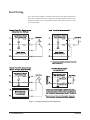
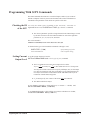
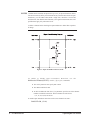
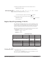
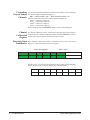
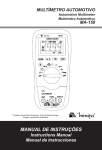
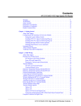
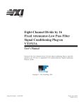
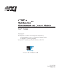
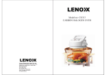
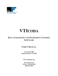
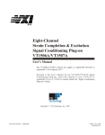
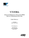
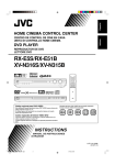
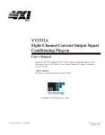
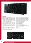
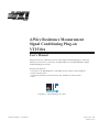
bus
4-Wire Resistance Measurement
Signal Conditioning Plug-on
VT1518A
User’s Manual
Enclosed is the User’s Manual for the VT1518A Signal Conditioning Plug-on. Insert this
manual in your VT1413C, VT1415A or an Agilent/HP E1313 or manual behind the “Signal
Conditioning Plug-ons” divider.
This SCP will operate in:
A VT1413C or an Agilent/HP E1313 with Flash revision A.06.02 or later, and Driver
revision A.09.00 or later.
A VT1415A with Flash revision A.03.00 or later, and Driver revision A.02.00
or later.
Copyright © VXI Technology, Inc., 2003
Manual Part Number:
82-0088-000
Printed: July 9, 2003
Printed in U.S.A.
VT1518A
Resistance Measurement
Signal Conditioning Plug-on
Introduction
The VT1518A is a Signal Conditioning Plug-on (SCP) that provides four
excitation current sources and four corresponding sense input channels. Each
current source can be programmed to provide either 30 µA or 488 µA. Each sense
input provides a fixed-gain amplifier (X16) with fixed bandwidth filtering (7 Hz).
Also provided is input over-voltage detection on all channels and Open Transducer
Detection on the four sense channels.
The SCP’s current source channels can be used with other input SCPs (different
gain and filter combinations) to provide a wide range of resistance measurement
capability. Also, this SCP’s sense inputs can be used as general purpose voltage
inputs with X16 gain (same characteristics as a VT1508A SCP).
About this Manual
This manual shows you how to control the Signal Conditioning Plug-on (SCP)
using SCPI commands as well as Register-Based commands, and explains the
capabilities of this SCP. Finally, it covers specifications for this SCP. Installation
for this Plug-on is common to several others and is covered in Chapter 1 your
VT1413C manual. The contents of this manual are:
·
·
·
·
·
·
Introduction
Field Wiring . . . . . . . . . . . . . . . . . . . . . . . . . . . . . . . . . . . . . . . . . . . . .
Connecting To The Terminal Module . . . . . . . . . . . . . . . . . . . . . . . . .
Programming With SCPI Commands . . . . . . . . . . . . . . . . . . . . . . . . .
Programming With Register Commands . . . . . . . . . . . . . . . . . . . . . . .
Current Source Channels Specifications . . . . . . . . . . . . . . . . . . . . . . .
Sense Channels Specifications . . . . . . . . . . . . . . . . . . . . . . . . . . . . . . .
4
5
7
11
13
15
VT1518A Resistance SCP 3
Field Wiring
The VT1518A SCP supplies excitation current from its four output channels (the
SCP’s first 4 channels) and senses voltage on its four input channels (the SCP’s last
4 channels). Figure 1 shows the general method of connection for both 4-wire and
2-wire connections.
Figure 1. Wiring for Resistance and Temperature
4 VT1518A Resistance SCP
Field Wiring
Connecting To The Terminal Module
This section shows how to make connections to the Terminal Module.
The SCP connections for the Terminal Modules are shown on the stick-on labels
that came with the SCP. Use the appropriate label for the type of Terminal Module
you have:
· For the VT1413C and VT1415A, use the label sheet marked C-size (Figure 2).
· For the Agilent/HP E1313A, use the label sheet marked B-size
(Figures 3 and 4).
· No label sheet is included for Agilent/HP E1413A/B connector module. In this
case follow the terminal module connection diagram in Figure 5.
Figure 2. VT1518A C-Size Terminal Module Connections
Connecting To The Terminal Module
VT1518A Resistance SCP 5
Figure 3. VT1518A B-size Terminal Module Connections (Ch 00-31)
Figure 4. VT1518A B-size Terminal Module Connections (Ch 32-63)
Figure 5. Agilent/HP E1413A/B Terminal Module Connections
6 VT1518A Resistance SCP
Connecting To The Terminal Module
Programming With SCPI Commands
The SCPI commands shown here are covered in Chapters 3 and 5 of your VT1413C
manual or Chapters 3 and 6 of your VT1415A manual. This section will relate those
commands to the parameter values which are specific to this SCP.
Checking the ID
of the SCP
To verify the SCP type(s) installed on the VT1413C, VT1415A or
Agilent/HP E1313 or use the SYSTem:CTYPe? (@<channel>) command.
· The channel parameter specifies a single channel in the channel range covered
by the SCP of interest. The first channel number for each of the eight SCP
positions are; 0, 8, 16 ,24, 32, 40, 48 and 56.
The value returned is:
HEWLETT-PACKARD,E1518A 4-Wire Resistance SCP,0,0
To determine the type of SCP installed on channels 0 through 7 send
Setting Current
Output Level
SYST:CTYP? (@100)
query SCP type @ ch 0
enter statement here
enter response string
To set the current output level use the
OUTPut:CURRent:AMPLitude <level>,(@<ch_list>) command.
· The level parameter can set the current output level to either
1
1
A)or 488 µA (
A). The default unit for level is Amps DC.
32768
2048
You may also include a units suffix to specify milliamps (ma), or microamps
(ua). The level parameter will also accept MIN (30 µA) and MAX (488 µA).
Use 488µA for resistance measurements under 2000 Ohms and 30 µA for
resistances of 2000 Ohms and greater.
30 µA (
· ch_list must specify one or more of the SCP’s first four channels.
· The *RST condition is 488mA.
To set channels 0 through 3 (SCP position 0) to measure < 2 kOhm, send
OUTP:CURR:AMPL 488E-6, (@100:103)
To set channels 8 through 11 (SCP position 1) to measure 2 kOhm to 32.7 kOhm,
send OUTP:CURR:AMPL 30ua,(@108:111)
Programming With SCPI Commands
VT1518A Resistance SCP 7
Querying the
Current Level
T o q u e r y a n y ch a n n e l to d e te r min e th e cu r r e n t lev e l u s e th e
O U TPut:CU R Ren t : A M P Li t u d e? ( @ <c h a n n e l>) co mman d . Th e
OUTP:CURR? command returns either +4.88E-4 or +3.0E-5.
· channel must specify a single one of the SCP’s first 4 channels.
To query the current level of channel 2 send
Turning Current
Source Channels
Off and On
OUTP:CURR:AMPL? (@102)
query channel 2
enter statement here
returns 4.88e-4 or 3.0e-5
T o d is a b le o r en a b le th e c u r r e n t s o u r c e c h a n n e l
OUTPut:CURRent[:STATe] <enable>,(@<ch_list>) command.
use
· The enable parameter can take the values ON or 1, and OFF or 0.
· ch_list must specify one or more of the SCP’s first four channels.
· The *RST condition is OFF.
To disable current source channels 0 through 3 (SCP position 0), send
OUTP:CURR:STAT OFF, (@100:103)
To enable current source channels 8 through 11 (SCP position 1), send
OUTP:CURR:STAT ON,(@108:111)
Querying the
Current Source
State
To query any channel to determine the current source output state use the
OUTPut:CURRent[:STATe]? (@<channel>) command. The OUTP:CURR?
command returns either a 1 for ON or a 0 for OFF.
· channel must specify a single one of the SCP’s first 4 channels.
To query the current state of channel 2 send
Querying the Filter
Cutoff Frequency
OUTP:CURR:STAT? (@102)
query channel 2
enter statement here
returns 1 or 0
While the VT1518A does not provide programmable cutoff frequency the filter
frequency can be queried. The response to this query will always be 7. To query any
channel for its cutoff frequency use the INPut:FILTer[:LPASs]:FREQuency?
(@<channel>) command. The INP:FILT:FREQ? command returns the numeric
cutoff value currently set for the channel specified.
· channel must specify a single one of the SCP’s last 4 channels.
To query the cutoff frequency of channel 6 (SCP position 0) send
8 VT1518A Resistance SCP
Programming With SCPI Commands
INP:FILT:FREQ? (@106)
query channel 6
enter statement here
Querying the
Filter State
While the VT1518A does not allow controlling whether the filters are enabled or
disabled, this state can be queried. The response to this query will always be 1. To
query any channel to determine if it is enabled or disabled use the
INPut:FILTer[:LPASs][:STATe]? (@<channel>) command. The INP:FILT?
command returns a 0 if the channel is OFF or a 1 if the channel is ON.
· channel must specify a single one of the SCP’s last 4 channels.
To query the filter state of channel 15 (SCP position 1) send
INP:FILT? (@115)
query channel 15
enter statement here
Querying the
Channel Gain
While the VT1518A’s amplifiers have fixed gain, the channel gain can be queried.
The response to this query will always be 16. To query any channel to determine its
gain setting use the INPut:GAIN? (@<channel>) command. The INP:GAIN?
command returns the current gain value for the specified channel.
· channel must specify a single one of the SCP’s last 4 channels.
To query the gain setting of channel 7 send
INP:GAIN? (@107)
query channel 7
enter statement here
Detecting Open
Transducers
Programming With SCPI Commands
VT1518A provides a method to detect open transducers connected to its 4 sense
channels. When Open Transducer Detect (OTD) is enabled, the SCP injects a small
current into the HIGH and LOW input of each channel. The polarity of the current
pulls the HIGH inputs toward +17 Volts and the LOW inputs towards -17 Volts. If a
transducer is open, measuring that channel will return an over-voltage condition.
OTD is available on a per SCP basic. all eight channels of an SCP are enabled or
disabled together. See Figure 6 for a simplified schematic diagram of the OTD
circuit.
VT1518A Resistance SCP 9
NOTES 1) When OTD is enabled, the inputs have up to 0.2 µA injected into them. If this
current will adversely affect your measurement, but you still want to check for open
transducers, you can enable OTD, make a single scan, check the CVT for bad
measurements, then disable OTD and make your regular measurement scans. The
specifications apply only when OTD is off.
2) Allow 5 minutes before checking for open transducers to allow filter capacitors
to charge.
Figure 6 Open Transducer Detect Circuit
T o e n a b le o r d is a b le O p e n Tr a n s d u c e r D e te c tio n , u s e th e
DIAGnostic:OTDetect[:STATe] <enable>, (@<ch_list>) command.
· The enable parameter can specify ON or OFF
· The *RST condition is OFF.
· An SCP is addressed when the ch_list parameter specifies one of the channel
numbers contained on the SCP. The first channel on each SCP is:
0, 8, 16, 24, 32, 40, 48 and 56
To enable Open Transducer Detection on all 4 sense channels on SCP 1:
DIAG:OTD ON, (@112)
10 VT1518A Resistance SCP
Programming With SCPI Commands
To disable Open Transducer Detection on all 4 sense channels on SCP 3:
DIAG:OTD OFF, (@128)
Querying the OTD
State
T o d e ter min e th e O T D s tate u s e th e
DIAGnostic:OTDetect[:STATe]? (@<channel>)
S CP I
c o mman d
· channel must specify a single one of the SCP’s last 4 channels.
To check the state of OTD for the VT1518A in SCP position 3 send
ch is first sense chan on SCP 3
DIAG:OTD? (@128)
enter statement here
Register Based Programming (VT1413C)
The register-based commands shown here are covered in Appendix D of the
VT1413C manual. You should read that section first to become familiar with
accessing registers and executing Register-Based Commands. This section will
relate those commands to the parameter values which are specific to this Plug-on.
When Register Programming an SCP most communication is through the Signal
Conditioning Bus. For that we’ll use the Register Commands:
SCBWRITE <regaddr> <regvalue>
and
SCBREAD? <regaddr>
VT1518A Register Map
Read (returned value)
Write( <regvalue>)
SCP Register
<regaddr> Value
SCP ID (AF0016)
Whole SCP Reg 0
00ppp000000 2
SCP Gain Scale (020216)
Whole SCP Reg 1
00ppp000001 2
Channel Control (ch 0-3 only) (XXX016=Off&Low,
XXX116=Off&High, XXX216=On&Low, XXX316=On&High)
Channel Reg 0
01pppccc0002
(ccc=0002 - 0112)
Channel Gain(Ch 0-3) (XX0016)
Channel Reg 1
01pppccc0012
Channel Gain(Ch 4-7) (XX0216)
Channel Reg 1
01pppccc0012
Channel Freq(Ch 0-3) (XX0316)
Channel Reg 2
01pppccc0012
Channel Freq(Ch 4-7) (XX0116)
Channel Reg 2
01pppccc0012
Calibration (Xnnn16)
where nnn=Cal Value
XX=don’t care
Checking ID of SCP
Channel Reg 7
01pppccc1112
ppp=Plug-on
ccc=SCP channel
To query an SCP for its ID value, write the following value to Parameter Register 1:
( SCP number ) ´ 4016
Then write the opcode for SCBREAD? (080016) to the Command Register. The ID
value will be written to the Query Response Register.
Register Based Programming (VT1413C)
VT1518A Resistance SCP 11
Controlling
Current Source
Channels
To set current amplitude and enable or disable an SCP channel, write the following
SCP channel address to Parameter Register 1:
200 16 + (SCP number) ´ 40 16 + (SCP channel number) ´ 8 16
Write one of the following control values to Parameter Register 2:
000016 = current low, output off
000116 = current high, output off
000216 = current low, output on
000316 = current high, output on
Then write the opcode for SCBWRITE (081016) to the Command Register.
Channel
Calibration
Register
The channel calibration registers control DACs that adjust the current output of
each current source channel. The Register-Based command CARDCAL? (100016)
controls these registers and the user should not write to them.
Detecting Open
Transducers
Open Transducer Detection (OTD) is controlled by bits in the Card Control
Register. For more information on OTD see Figure 1.
Card Control Register
(Base + 1216)
15
14
14-13
12
11
10-8
7-0
PSI Pwr Reset
FIFO Mode
unused
FIFO Clear
VPPEN
A24 Window
Open Transducer Detect
Writing a one (1) to a bit enables open transducer detect on that signal conditioning
module. Writing a zero (0) to a bit disables open transducer detect.
12 VT1518A Resistance SCP
Bit 7
Bit 6
Bit 5
Bit 4
Bit 3
Bit 2
Bit 1
Bit 0
SCP 7
SCP 6
SCP 5
SCP 4
SCP 3
SCP 2
SCP 1
SCP 0
Register Based Programming (VT1413C)
SCP Current Requirements
Supply
Typical
Maximum
+5 V
7 mA
10 mA
+24 V
28 mA*
33 mA*
-24 V
33 mA*
39 mA*
* with 488 µA output on all 4 Chs
Current Source Specifications
The general specifications for the VT1518A reflect the performance of the current
source section by itself. The resistance performance specification reflects the
combined performance of the VT1413C or VT1415A and the SCP.
General Specifications
Compliance
Output Amplitude
Output Accuracy
L terminal is at ground
H terminal±16 V with respect to ground
Nominal (µA)
Actual (A)
30
1
32768
488
1
2048
(90 days) 23°C±1°C (with *CAL? done after 1 hr warm up)
Current
Amplitude (µA)
Output
Accuracy
30.518
488.28
±9 nA
±60 nA
Current
Amplitude (µA)
Temperature
Coefficient
30.518
488.28
±0.9 nA/°C
± 6 nA/°C
Temperature Coefficient
Ripple and Noise
SCP Current Requirements
(7.5 kOhm resistor to L, 3 sigma)
Current
Amplitude (µA)
Ripple and
Noise
30.518
488.28
±9 nA
± 15 nA
VT1518A Resistance SCP 13
(7.5 kOhm resistor to L)
Off Leakage Current
Less than±10 nA
Less than (±10 nA + 1.6 nA/°C)
0 - 30°C
30 - 55°C
(90 days) 23°C±1°C (with *CAL? done after 1 hr warm up and CAL:ZERO? within
5 min.).
Resistance Specifications
Range FS
(Ohms)
Current
Amplitude (µA)
(A/D Range VDC)
Maximum
Resolution (W)
32.77k
8.192k
2.048k
2.048k
512
128
32
30.518
30.518
30.518
488.28
488.28
488.28
488.28
16
4
1
16
4
1
0.25
1
0.25
0.0625
0.0625
0.0156
0.0039
0.0009
(Four-Wire connection)
Resistance Accuracy
Gain:*
Offset: W*
Noise: W*
Current
Amplitude
Resistance
Accuracy
30.518 µA
488.28 µA
0.035% of reading
0.02% of reading
offset of input SCP (in Volts)
current source value (in Amps)
Range VDC
Noise @ 30 µA
Noise @ 488 µA
0.0039
0.0156
0.0625
0.25
1
0.161 W
0.262 W
1.02 W
0.008 W
0.009 W
0.010 W
0.016 W
0.063 W
noise of input SCP (in Volts)
current source value (in Amps)
Range VDC
Noise @ 30 µA
Noise @ 488 µA
0.0039
0.0156
0.0625
0.25
1
0.245 W
0.917 W
03.70 W
0.007 W
0.009 W
0.015 W
0.057 W
0.231 W
* Specs apply only with Open Transducer Detect OFF
14 VT1518A Resistance SCP
Sense Channel Specifications
Sense Channel Specifications
These specifications for the sense section reflect the combined performance of the
VT1413C, VT1415A or Agilent/HP E1313 and the VT1518A Signal Conditioning
Plug-on. These specifications are not to be added to those presented in the
VT1413C or VT1415A User’s Manual.
General Specifications
Measurement ranges
±3.9 mV to ±1 V FS
DC Volts
Temperature
Resistance
Thermocouples - -200 to +1700°C
Thermistors - (Opt 15 required) -80 to +160°C
RTD’s - (Opt 15 required) -200 to +850°C
8 Ohms to 32 kOhms FS (X16 sense channel)
128 Ohms to 524 kOhms FS (X1 sense channel)
Maximum input voltage
Operating: <±16 V peak
Damage level: >±42 V peak
Operating: <±16 V peak
Damage level: >±42 V peak
(Normal mode plus common mode)
Maximum common mode
voltage
@ 7 Hz -3 dB, @ 60 Hz >-25 dB
Normal mode rejection
0 - 60 Hz -100 dB
Common mode rejection
100 MOhm ±10% (each differential input to ground)
Input impedance
(Maximum tare offset depends on A/D range and SCP gain)
Maximum tare cal offset
Measurement accuracy
DC Volts
Sense Channel Specifications
A/D range
±V F.Scale
16
4
1
0.25
0.0625
Max Offset
0.20009
0.05007
0.01317
0.00349
0.00112
(90 days) 23°C±1°C (with *CAL? done after 1 hr warm up and CAL:ZERO? within 5
min.). If autoranging is ON, add ±0.02% FS to accuracy specifications.
For Agilent/HP E1313, multiply Noise Spec. by 1.4.
VT1518A Resistance SCP 15
Gain 16
Range
±V FS
Linearity
% of reading
Offset Error
µV (10 Hz)
Noise µV
3 sigma
Noise µV*
3 sigma
0.0039
0.0156
0.0625
0.25
1
0.01
0.01
0.01
0.01
0.01
3.8
4.2
4.9
8
31
3.4
4.4
7.5
28
113
2.9
3.8
6.3
23
64
* [SENSe:]FILTer[:LPASs][:STATe] ON (max scan rate - 100 readings/s/channel)
Temperature Coefficients: Gain - 15ppm/°C. Offset - (0 - 30°C) 0.16 µV/°C, (30 - 40°C) 0.18 µV/°C,
(40 - 55°C) 0.39 µV
(90 days) 23°C±1°C (with *CAL? done after 1 hr warm up and CAL:ZERO? within 5
min.). If autoranging is ON, add ±0.02% FS to accuracy specifications.
Measurement accuracy
Temperature
The temperature accuracy specifications include instrument and firmware linearization
errors. The linearization algorithm used is based on the IPTS-68(78) standard transducer
curves. Add your transducer accuracy to determine total measurement error.
(simplified specifications, see
temperature accuracy graphs in
VT1413C manual for details)
Thermocouples
Type E
Type EEXtended
Type J
Type K
Type R
Type S
Type T
16 VT1518A Resistance SCP
A/D Filter
-200 to 0°C
0 to 200°C
200 to 400°C
400 to 800°C
OFF
1.30°C
0.14°C
0.14°C
0.20°C
A/D Filter
-200 to 0°C
0 to 200°C
200 to 800°C
800 to 1000°C
OFF
1.80°C
0.30°C
0.20°C
0.35°C
A/D Filter
-200 to 0°C
0 to 280°C
280 to 600°C
600 to 775°C
OFF
1.60°C
0.15°C
0.22°C
0.22°C
A/D Filter
-200 to 0°C
0 to 375°C
375 to 800°C
800 to 1400°C
OFF
2.50°C
0.20°C
0.25°C
0.40°C
A/D Filter
0 to 100°C
100 to 200°C
200 to 600°C
600 to 1000°C
OFF
1.80°C
0.90°C
0.70°C
0.60°
A/D Filter
0 to 100°C
100 to 200°C
200 to 800°C
800 to 1750°C
OFF
3.50°C
1.75°C
0.80°C
0.85°C
A/D Filter
-200 to -100°C
-100 to 0°C
0 to 200°C
200 to 400°C
OFF
1.55°C
0.32°C
0.18°C
0.18°C
Sense Channel Specifications
5 kW Reference Thermistor
A/D Filter
-10 to 65°C
65 to 85°C
OFF
0.012°C
0.013°C
A/D Filter
-125 to 70°C
OFF
0.145°C
A/D Filter
-200 to 75°C
75 to 300°C
300 to 600°C
600 to 970°C
OFF
0.08°C
0.21°C
0.27°C
0.37°C
A/D Filter
0 to 30°C
30 to 70°C
70 to 80°C
80 to 100°C
OFF
0.006°C
0.013°C
0.010°C
0.014°C
A/D Filter
0 to 30°C
30 to 70°C
70 to 85°C
OFF
0.012°C
0.014°C
0.019°C
A/D Filter
0 to 30°C
30 to 60°C
60 to 90°C
90 to 115°C
OFF
0.015°C
0.016°C
0.018°C
0.022°C
100 W Reference RTD
100 W RTD
2252 W Thermistor
5 kW Thermistor
10 kW Thermistor
Sense Channel Specifications
VT1518A Resistance SCP 17
Notes
18 VT1518A Resistance SCP
Sense Channel Specifications