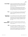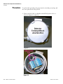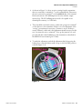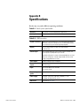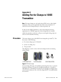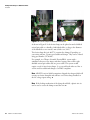
1
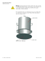
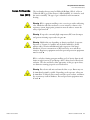
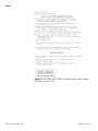
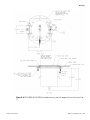
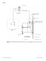
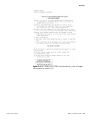
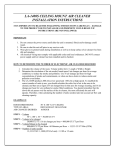
MOLA-LS Limited Source Moisture Online Analyzer Installation Guide P/N 717907 Revision F Part of Thermo Fisher Scientific MOLA-LS Limited Source Moisture Online Analyzer Installation Guide P/N 717907 Revision F © 2010 Thermo Fisher Scientific Inc. All rights reserved. “Windows” is either a registered trademark or trademark of Microsoft Corporation in the United States and/or other countries. “HART” is a registered trademark of the HART Communication Foundation. “Fisher-Rosemount” is either a trademark or registered trademark of Emerson Electric Company. All other trademarks are the property of Thermo Fisher Scientific Inc. and its subsidiaries. Thermo Fisher Scientific Inc. (Thermo Fisher) makes every effort to ensure the accuracy and completeness of this manual. However, we cannot be responsible for errors, omissions, or any loss of data as the result of errors or omissions. Thermo Fisher reserves the right to make changes to the manual or improvements to the product at any time without notice. The material in this manual is proprietary and cannot be reproduced in any form without expressed written consent from Thermo Fisher. This page intentionally left blank. Revision History Thermo Fisher Scientific Revision Level Date Comments A 07-2007 Initial release (per ERO 5697). B 08-2007 Revised per ECO 5924. C 05-2008 Revised per ECO 6363. D 10-2009 Revised per ECO 7127. E 08-2010 Revised per ECO 7456. F 09-2010 Revised per ECO 7504. MOLA-LS Installation Guide v This page intentionally left blank. Contents Safety Information & Guidelines ..................................................................... ix Safety Considerations .............................................................................ix 7200A Safety Cover Notice....................................................................ix Boron Trifluoride Gas (BF3)..................................................................xi Warnings, Cautions, & Notes ...............................................................xii Thermo Fisher Scientific Chapter 1 Product Overview ............................................................................................. 1-1 Associated Documents ........................................................................ 1-1 Chapter 2 Handling & Storage .......................................................................................... 2-1 ESD Procedures .................................................................................. 2-1 Unpacking, Inspection, & Storage ...................................................... 2-2 Packing, Shipping, Transporting, & Receiving.................................... 2-2 Chapter 3 Hardware Installation...................................................................................... 3-1 Installation Considerations.................................................................. 3-1 Licensing.......................................................................................... 3-1 Guidelines........................................................................................... 3-2 General ............................................................................................ 3-3 Power Requirements ........................................................................ 3-3 Mounting & Installation..................................................................... 3-4 The Transmitter............................................................................... 3-4 The Detector.................................................................................... 3-4 Chapter 4 Wiring.................................................................................................................. 4-1 Preparation.......................................................................................... 4-1 Detector.............................................................................................. 4-2 The Transmitter.................................................................................. 4-2 EMC Requirement for ATEX Version of 1400S Transmitters ......... 4-2 Board Configurations....................................................................... 4-3 General Wiring Procedure................................................................ 4-3 Power Supply ...................................................................................... 4-4 AC Power......................................................................................... 4-4 DC Power ........................................................................................ 4-4 Current Output .................................................................................. 4-5 Relays............................................................................................... 4-5 Contact Closure (Switch) Inputs ...................................................... 4-5 Serial Communications ....................................................................... 4-5 MOLA-LS Installation Guide vii Contents RS232 .............................................................................................. 4-5 Using Serial Communications.......................................................... 4-6 HART Communications..................................................................... 4-6 Chapter 5 Mechanical Zero Adjustment for BF3 Detectors ........................................5-1 Overview............................................................................................. 5-1 Procedure............................................................................................ 5-2 Chapter 6 Service.................................................................................................................6-1 Getting Help....................................................................................... 6-1 Appendix A Ordering Information .......................................................................................A-1 Appendix B Specifications...................................................................................................B-1 Appendix C Drawings............................................................................................................ C-1 Appendix D Site Readiness Form ........................................................................................D-1 Appendix E Adding Ferrite Clamps to 1400S Transmitter .............................................. E-1 Procedure............................................................................................E-1 Index ..........................................................................................................INDEX-1 viii MOLA-LS Installation Guide Thermo Fisher Scientific Safety Information & Guidelines This chapter contains information that must be read and understood by all persons installing, using, or maintaining this equipment. Safety ty Considerations Failure to follow appropriate safety procedures or inappropriate use of the equipment described in this manual can lead to equipment damage or injury to personnel. Any person working with or on the equipment described in this manual is required to evaluate all functions and operations for potential safety hazards before commencing work. Appropriate precautions must be taken as necessary to prevent potential damage to equipment or injury to personnel. The information in this manual is designed to aid personnel to correctly and safely install, operate, and/or maintain the system described; however, personnel are still responsible for considering all actions and procedures for potential hazards or conditions that may not have been anticipated in the written procedures. If a procedure cannot be performed safely, it must not be performed until appropriate actions can be taken to ensure the safety of the equipment and personnel. The procedures in this manual are not designed to replace or supersede required or common sense safety practices. All safety warnings listed in any documentation applicable to equipment and parts used in or with the system described in this manual must be read and understood prior to working on or with any part of the system. Failure to correctly perform the instructions and procedures in this manual or other documents pertaining to this system can result in equipment malfunction, equipment damage, and/or injury to personnel. 7200A Safety Cover Notice Warning Read and abide by all safety precautions when handling nuclear devices. It is the operator’s responsibility to understand and follow all safety precautions. ▲ Each 7200A unit will be shipped with one safety cover with fastening hardware and packaged within the shipping container. The image below shows what this cover looks like when it is not installed and where it should be installed. The safety cover kit assembly part number is 341-720001 and includes the safety cover and fasteners. Install the safety cover only if removing the 7200A source housing unit for service or repair. Install the cover with the text facing outward. Thermo Fisher Scientific MOLA-LS Installation Guide ix Safety Information & Guidelines 7200A Safety Cover Notice Warning Since this top hat unit contains a nuclear source, the cover must be installed immediately after the source housing is removed. Failure to do so can result in exposure to radiation if you reach into the top hat, intentionally or unintentionally. ▲ Do not discard the safety cover and fasteners for any reason. If the safety cover and fasteners are missing, contact Thermo Fisher immediately to order a new safety cover kit. Safety cover for 7200A unit x MOLA-LS Installation Guide Thermo Fisher Scientific Safety Information & Guidelines Boron Trifluoride Gas (BF3) Boron oron Trifluoride Gas (BF3) The ion chamber detector may be filled with Helium-3 (He3) or Boron Trifluoride (BF3) gas. If the detector is filled with BF3, it is critical to read this section carefully. The type of gas is identified on the instrument housing. Warning BF3 is a pungent smelling, toxic, corrosive gas with a suffocating odor. Inhalation will cause moderate to severe irritation or burns to the respiratory system. Appropriate precautions must be taken to ensure the safety of personnel. ▲ Warning If exposed to extremely high temperatures, BF3 can decompose and generate irritating vapors and toxic gases. ▲ Warning Health risks vary depending on duration and level of exposure. Exposure to 50 ppm, for example, may be fatal if inhaled for 30–60 minutes (due to massive inflammation and congestion of the lungs). Inhalation of lower concentrations of BF3 can lead to nose and throat irritation. Respiratory equipment and other personal protection equipment must be used. ▲ BF3 is a colorless, fuming, pungent smelling gas. It is heavier than air and fumes strongly in moist air, producing a dense, white cloud of fluoroboric acid mist. The odor and dense, white appearance of this gas, upon release, are distinctive warning properties associated with it. Warning Fluoroboric acid mist can burn the skin or eyes. Burns may not be immediately painful or visible. Depending on the exposure, effects can be immediate or delayed. Skin contact can lead to pain, redness, and burns. Eye contact may result in blindness. Personal protection equipment must be used. ▲ Thermo Fisher Scientific MOLA-LS Installation Guide xi Safety Information & Guidelines Warnings, Cautions, & Notes Warnings, arnings, Cautions, & Notes The following admonitions are used throughout this manual to alert users to potential hazards or important information. Failure to heed the warnings and cautions in this manual can lead to injury or equipment damage. Warning Warnings notify users of procedures, practices, conditions, etc. which may result in injury or death if not carefully observed or followed. The triangular icon displayed with a warning may contain a lightning bolt or the radiation symbol, depending on the type of hazard. ▲ Caution Cautions notify users of operating procedures, practices, conditions, etc. which may result in equipment damage if not carefully observed or followed. ▲ Note Notes emphasize important or essential information or a statement of company policy regarding an operating procedure, practice, condition, etc. ▲ xii MOLA-LS Installation Guide Thermo Fisher Scientific Chapter 1 Product Overview Refer to the MOLA-LS user guide (p/n 717906) for descriptions of instrument functions and features. Associated Documents Thermo Fisher Scientific In addition to this guide, the following documents must be read and understood by all persons installing, using, or maintaining this equipment: ● MOLA-LS user guide (p/n 717906) ● Neutron Radiation Safety (p/n 717905) MOLA-LS Installation Guide 1-1 This page intentionally left blank. Chapter 2 Handling & Storage This chapter addresses procedures for handling electrostatic discharge (ESD) sensitive equipment, as well as procedures for unpacking, inspecting, and storing of the system. Caution This system is an ESD sensitive instrument. Use proper ESD protective equipment and procedures. Failure to comply with ESD procedures can result in circuit damage. ▲ ESD SD Procedures The instrument contains electronic components that can be damaged from discharges of static electricity: Do not touch the circuit board components. Ordinarily, handling the circuit boards by their edges will not damage the circuits. Observe the following when installing, setting up, servicing, troubleshooting, or repairing the instrument: 1. Use an antistatic bag. Most instrument subassemblies are shipped in a special antistatic bag. When not installed, keep the assembly in the bag as often as possible. 2. Remove ESD sensitive subassemblies only under the following conditions: a. When at a designated static-free workstation or when the bag is grounded at a field site. b. After the conductive area of the container has been neutralized. c. After making firm contact with an antistatic mat and/or firmly gripping a grounded individual. 3. Personnel handling ESD sensitive devices should be neutralized to a static-free workstation by means of a grounding wrist strap that is connected to the station or to a good grounding point at the field site. 4. Do not allow clothing to make contact with ESD sensitive devices. Thermo Fisher Scientific MOLA-LS Installation Guide 2-1 Handling & Storage Unpacking, Inspection, & Storage 5. Avoid touching edge connectors and components. 6. Avoid partially connecting ESD sensitive devices. These devices, especially the power supply connector, can be damaged by floating leads. 7. Ground test equipment. 8. Avoid static charges during troubleshooting. Unpacking, Inspection, & Storage Note Inspection, adjustment, installation, and maintenance of the instrument must be performed by experienced personnel only. ▲ 1. Upon receipt, inspect the instrument for damage that may have occurred while in transit. If there is evidence of rough handling or damage, file a damage claim with the transportation company immediately. Notify Thermo Fisher and/or your sales representative as soon as possible. 2. Carefully inspect the packing material prior to discarding it to ensure that all equipment and instruction paperwork has been removed. 3. Use the original packing material and container for storage if necessary. 4. If storing the instrument, the storage environment should be protected, free from extremes of temperatures and high humidity, and fall within the environmental constraints listed in the specifications. Packing, Shipping, Transporting, & Receiving 2-2 MOLA-LS Installation Guide All personnel involved in the packing, shipping, or receiving of hazardous material must be trained in accordance with the United States Department of Transportation (DOT) and OSHA hazardous materials regulations or in accordance with the Canadian Nuclear Safety Commission (CNSC) regulations. Thermo Fisher Scientific Chapter 3 Hardware Installation Read the radiation safety guide (p/n 717905) prior to installing the equipment. Installation Considerations This section details the recommended installation procedures for standard applications. If these procedures do not adequately address your particular application, contact Thermo Fisher for recommendations that are more specific. In all cases, radiation safety is a principal concern in the design and manufacture of the system. When properly installed, the system presents no hazards to personnel. The neutron source is surrounded by an air space. The source housing is shipped with the source shutter locked and in the OFF position. This lock must remain in place until installation is complete and the equipment is ready for start-up and calibration. The system may only be used in those hazardous locations identified on the product nameplates. The system consists of four components: ● 1400S transmitter: stainless steel (NEMA 4X) ● 7200A ion chamber detector (powered by transmitter) ● 7200A source housing (neutron source housing) ● 7200A mounting base plate Licensing icensing Warning The instrument is a nuclear device regulated by federal and / or state authorities. You are responsible for knowing and following the pertinent safety and regulatory requirements. Refer to the neutron radiation safety guide (p/n 717905) for a summary of these requirements. ▲ Warning Moving or removing an installed source housing or any assembly that includes a source housing requires a person who is specifically licensed to install and commission Thermo Scientific source heads. ▲ Thermo Fisher Scientific MOLA-LS Installation Guide 3-1 Hardware Installation Guidelines In the United States, your general license permits you to own and install all of the instrument’s components, including the source head. However, you may not commission the instrument (remove the lock and open the source housing shutter for the first time) without a specific license authorizing radiation commissioning of the instrument. In Canada, you are only allowed to remove the MOLA from the shipping container if your CNSC license has a condition authorizing mounting / dismounting of devices. For assistance obtaining a license and / or commissioning / decommissioning the instrument, contact Thermo Fisher. Guidelines Warning Do not install the system in any hazardous area other than those approved. Refer to the equipment tag for the specific approvals applicable to the configuration of your instrument. ▲ Warning Do not apply power to the instrument in any hazardous area unless the safety ground is properly wired inside the instrument and the cover is properly installed. ▲ Approvals for the 1400S transmitter and the 7200S ion chamber detector are listed in Appendix B. For ATEX certified detectors: 3-2 MOLA-LS Installation Guide ● When used in ambient temperatures greater than 60°C (140°F), cable rated for at least 80°C (176°F) must be used. ● No changes permitted to any flamepath without reference to scheduled drawings. ● Equipment (except junction box) must not be opened by installer, user, or maintainer. Equipment shall only be opened by the manufacturer or their representative. Thermo Fisher Scientific Hardware Installation Guidelines General Review the following guidelines when planning gauge installation: 1. Correct power source is available (see “Power Requirements” later in this chapter). 2. Operating temperature ranges (non-ATEX applications): a. 1400S transmitter: -40°C to +60°C (-40°F to +140°F) b. 7200A ion chamber detector: Standard: -40°C to +75°C (-40°F to +167°F) Optional extreme temperatures: -50°C to +85°C (-58°F to +185°F) 3. The transmitter should be mounted so that the display is easily seen and the keypad on the transmitter is easily accessible. 4. The transmitter should not be mounted near high voltage, high current, corrosive vapors, corrosive liquids, or corrosive esters. 5. There should be enough clearance to install and service the source and the detector. Refer to the dimensional drawings in the drawing appendix. 6. Source housing should be positioned so that the radioactive source identification tag is visible. The source housing tag should be upright. 7. The gauge should not be mounted where process overflow or other material can collect in the beam path. The source shutter mechanism must be kept free of debris. 8. The maximum cable length between the transmitter and the last detector should not exceed 2500 feet (762 m). Power Requirements 1. 1400S transmitter: a. Standard: 100–240 Vac, 50/60 Hz, 17.2 W b. Optional: 20–28 Vdc, 12 W 2. 7200A ion chamber detector: Powered by transmitter Thermo Fisher Scientific MOLA-LS Installation Guide 3-3 Hardware Installation Mounting & Installation Mounting & Installation Warning Do not install the system in any hazardous area other than those approved. Refer to the equipment tag for the specific approvals applicable to the configuration of your instrument. ▲ Warning Do not apply power to the instrument in any hazardous area unless the safety ground is properly wired inside the instrument and the cover is properly installed. ▲ Note You will need to supply the necessary brackets and hardware required for mounting the gauge to your particular vessel. ▲ The Transmitter 1. Refer to drawing 208-140002 in the drawing appendix for dimensions. 2. Mount the transmitter in one of the following two ways: Mount the transmitter with four screws by placing one screw through each of the four holes in the transmitter enclosure’s flange and tightening. OR Mount the transmitter with four nuts, four bolts, and eight washers by placing one bolt through each of the four holes in the transmitter enclosure’s flange, placing one washer on each side. Screw on the nuts, and tighten the bolts. The Detector Warning Installation must be in accordance with local and national electric codes for the area classifications. ▲ Caution The source housing handle must be in the OFF position during installation. ▲ Caution Use proper lifting procedures to avoid injury. ▲ Warning Do not reach inside the source housing at any time during installation. ▲ Refer to the drawings in the drawing appendix for installation instructions. A typical steel mill hopper installation is shown in Figure 3–1. 3-4 MOLA-LS Installation Guide Thermo Fisher Scientific Hardware Installation Mounting & Installation Figure 3–1. Typical installation (no wear liner) Thermo Fisher Scientific MOLA-LS Installation Guide 3-5 This page intentionally left blank. Chapter 4 Wiring Wiring should be performed in the following order: 1. Power to the transmitter 2. The detector to the transmitter 3. Optional wiring: a. Relay contacts b. 4–20 mA current output(s) c. Contact closure inputs d. Serial communications Preparation reparation Review the following carefully prior to connecting any wiring. Warning Remove all power from the unit before making any connections. Electrocution can result if power is present. ▲ Warning Do not apply power to the instrument in any hazardous area unless the safety ground is properly wired inside and the cover is properly installed. ▲ Warning All wiring must be done by qualified individuals in accordance with applicable codes such as the National Electric Code (NEC) ANSI/NFPA 70 specifications or the Canadian Electrical Code Part 1. ▲ Warning Before wiring the gauge, verify that the source shutter is in the off position. ▲ Warning For hazardous location installations, the cable entries must be sealed per the installation layout drawing. ▲ Thermo Fisher Scientific MOLA-LS Installation Guide 4-1 Wiring Detector Warning If metal conduit is used, the conduit must be grounded. ▲ Warning Do not rotate junction box during installation or damage may occur to internal wiring. ▲ Note To meet the requirements of CSA 1010.1, an external switch or circuit break must be installed to allow the power source to be disconnected from the gauge. In addition, the protective bonding (grounding) must always be provided, even if a dc power source is used. ▲ Detector The detector is completely powered from the transmitter. Refer to sheet 3 of drawing 868680-6 for junction box terminal wiring. The six-conductor cable provides ±15 Vdc input to the detector, +24 Vdc loop power, and carries the 0–20 mA signal from the detector to the transmitter. A common ground is used. The transmitter-to-detector wiring will be addressed in the next section. The only other electrical connection to the detector is the safety ground. The Transmitter EMC Requirement for ATEX Version of 1400S Transmitters In order for the 1400S transmitter to meet electromagnetic emission requirements for CE-EMC approvals, ferrite clamps must be installed within the transmitter enclosure on all power and signal wiring going into and out of the transmitter housing. One ferrite clamp is installed on the wires of the AC power supply input. Five additional ferrite clamps are provided with the EMC ferrite clamps kit (p/n 868773). The installation procedure accompanies the kit. It is also provided in Appendix E. Note The ferrite clamps are only used in the ATEX version of the 1400S transmitter. They are not required for the CSA version. ▲ 4-2 MOLA-LS Installation Guide Thermo Fisher Scientific Wiring The Transmitter Board Configurations General Wiring Procedure Refer to drawing 868680-6 in the drawing appendix. The transmitter has slots for the following boards: ● AC power supply ● CPU board with KIB piggyback board (886722-1 PWA) ● PCB 1: Standard current I/O DC power board in one of the following configurations ● Optional 24 Vdc input power and current I/O #1, 2 contact inputs, 2 relays ● Optional 12 Vdc input power and current I/O #1, 2 contact inputs ● PCB 2: Optional current I/O board, 2 contact inputs, 2 relays ● PCB 3: Optional current I/O board, 2 contact inputs, 2 relays ● PCB 4: Optional VPI board, used to input 0–20 mA detector signal Follow this general procedure to wire boards installed in the transmitter. Note CSA certified fittings must be used to maintain CSA rating for the enclosure. ▲ 1. Ensure power to the gauge is removed, and open the enclosure cover. 2. Remove the plugs only from the cable conduit holes you will use. The holes are labeled on the transmitter enclosure. 3. Pull the cable through the fitting on the end of the enclosure, leaving approximately 6 inches (150 mm) of stress relief. Secure the conduit, making sure it is completely sealed. 4. For ATEX versions of the 1400S: Install a ferrite clamp on all wiring. You will need kit 868773. Refer to Appendix E. Thermo Fisher Scientific MOLA-LS Installation Guide 4-3 Wiring Power Supply 5. Connect a cable to the PCB as follows: a. Remove the plug-in screw terminal connector from the board connector. The connector should be tightly seated. To remove the connector, brace the board with your hand, being careful not to touch any of the circuits or components. b. Loosen the screws on the plug-in connector. c. Insert the wires, and make connections as shown in the appropriate installation wiring drawing. d. Tighten the screws in the connector to secure the wires. e. Plug the screw terminal connector back into the corresponding onboard connector. 6. When all connections are completed, close and secure the transmitter cover. Power Supply AC Power With AC power, the system is designed to operate on 100–240 Vac, at an input frequency of 50/60 Hz. The system can be wired directly to either 115 or 230 Vac, and the maximum input power requirement is 25 VA when all options are present. Refer to drawing 868680-6 for wiring requirements. To connect AC power to the transmitter: 1. Connect AC power input (L and N) to the J1 terminal block. 2. Connect electrical safety ground to a dedicated safety ground terminal. DC Power Note To meet the requirements of CSA 1010.1, the input DC terminals must be supplied from a SELV (Safety Extra Low Voltage) source. ▲ With 24 Vdc input power, the system is designed to operate on 20–28 Vdc. The maximum input power requirement is 12 W when all options are present. Refer to drawing 868680-6 for wiring requirements. Follow these steps to connect 24 Vdc power to the transmitter: 1. Connect +24 Vdc to pin 8 of the J5 connector on the current I/O #1 (PCB 1) board. 2. Connect the return for the +24 Vdc supply to ground, pin 9 of J5. 4-4 MOLA-LS Installation Guide Thermo Fisher Scientific Wiring Current Output Current Output One current output (I/O) board is supplied as standard. It is installed in the PCB 1 slot. Two additional I/O boards can optionally be installed in the PCB 2 and PCB 3 slots. The current output is programmable between 0 and 20 mA. The minimum output is approximately 3 mA, and the maximum load is 750 ohms. The current output is normally shipped with an isolated, self-powered output configuration, but can be reconfigured with an isolated, looppowered configuration by removing the jumper from pins 3 and 4 on the J5 connector on the I/O board. In the loop-powered configuration, you must supply +24 Vdc loop power to pin 3 of J5; pin 2 of J5 is Iout+. Relays Two or four relays are available as options on the I/O board in the PCB 1 slot. Refer to the installation wiring drawing and the label inside the transmitter cover for wiring details. Relay contacts are Form C SPDT, isolated 8 A, 220 Vac. Contact Closure (Switch) Inputs Two user provided contact closure inputs are included on each I/O board. The contact closure inputs are dry contact inputs between ground and Switch 1 and ground and Switch 2. The instrument can be configured via software settings to execute a command or other functions upon a user provided contact opening or closing. Refer to the MOLA-LS user guide (p/n 717906) for instructions on assigning commands to the contact closure inputs. Serial Communications The instrument provides an RS232 single-drop serial interface. Screw terminal connectors for the ports are located on the CPU board. The RS232 port is not normally used as the primary means of communication for setup or calibration. RS232 Thermo Fisher Scientific Refer to the 1400S transmitter wiring drawings (868680-6) for RS232 wiring details. The serial port on a PC (COM1 or COM2) can be connected directly to the RS232 port on the instrument. This requires five wires: ground, transmit (TX), receive (RX), RTS, and CTS. The connection between the instrument port connector (located on the CPU board in the transmitter) and the PC serial port are summarized in the following table for standard DB9 and DB25 PC serial port connectors. MOLA-LS Installation Guide 4-5 Wiring HART Communications Table 4–1. RS232 connections Using Serial Communications CPU Board (J8) RS232 Connector PC Serial Port DB9 Connector PC Serial Port DB25 Connector Pin 1 of J8 (RTS) Pin 8 Pin 5 Pin 2 of J8 (TX) Pin 2 Pin 3 Pin 3 of J8 (CTS) Pin 7 Pin 4 Pin 4 of J8 (RTS) Pin 3 Pin 2 Pin 5 of J8 (GND) Pin 5 Pin 7 To communicate with the instrument from a PC requires the PC be running TMTComm, a Windows-based software, or another terminal emulation software, such as Hyper Terminal. The default communication settings for the RS232 port of the instrument are: ● Data bits: 7 ● Parity: Even ● Stop bits: 1 ● Baud rate: 9600 Refer to the MOLA-LS user guide (p/n 717906) for additional details about setting up and using serial communications. HART Communications 4-6 MOLA-LS Installation Guide The HART® communication protocol is supported over the 4–20 mA current output with an optional daughter board. You can communicate with the instrument using the 275 or 375 Field Communicator from Emerson Electric Co. Thermo Fisher Scientific Chapter 5 Mechanical Zero Adjustment for BF3 Detectors Warning BF3 is a pungent smelling, toxic, corrosive gas with a suffocating odor. Inhalation will cause moderate to severe irritation or burns to the respiratory system. Appropriate precautions must be taken to ensure the safety of personnel. ▲ Note If your neutron backscatter detector uses He3 gas instead of BF3 gas in the ion chamber, there will be no mechanical “zeroing” potentiometer in the junction box. This chapter applies only to detectors using BF3 gas. ▲ Overview verview Inside the terminal block junction box on the detector is a “zeroing” potentiometer. After system installation, this potentiometer must be checked and possibly adjusted. This chapter provides the instructions for doing so. Note The detector assembly must be installed in its operational location long enough for all physical components to reach ambient temperature before performing this procedure. A 12 to 18-hour acclimatization period is recommended. ▲ Note The “zeroing” potentiometer is set at the factory and may not need adjustment. Therefore, do not unlock the adjustment knob until verifying that adjustment is required. ▲ Note This procedure must be done with no process material in front of the detector. There must be no moisture or hydrocarbons in front of the MOLA when performing this procedure, i.e. an empty, cold vessel. Also watch for the presence of personnel or other sources of hydrogen near the gauge head as they may introduce an unwanted signal. ▲ Thermo Fisher Scientific MOLA-LS Installation Guide 5-1 Mechanical Zero Adjustment for BF3 Detectors Procedure Procedure To perform this procedure, the gauge must be wired and powered up, and the source placed in the ON position. 1. Remove the lid of the ion chamber terminal block junction box, as shown in Figures 5–1 and 5–2. Figure 5–1. Figure 5–2. 5-2 MOLA-LS Installation Guide Thermo Fisher Scientific Mechanical Zero Adjustment for BF3 Detectors Procedure 2. As shown in Figure 5–2, there are wires coming from the transmitter that are connected to terminals 3–7 on the terminal block. Disconnect the wire connected to terminal 7 on the unlabeled side of the terminal block and connect a DC milliamp meter in series with the output current loop. The DC milliamp meter needs to be capable of two decimal place accuracy (i.e. X.XX mA). 3. There should be a 4.00 mA current (± 0.02 mA) going from terminal 7 on the detector to the transmitter. If there is not, an adjustment of the “zeroing” potentiometer is necessary. Continue to step 4. If there is exactly 4.00 mA (± 0.02 mA), then adjustment is not necessary. In this case, reconnect the wire to terminal 7, close up the junction box, and proceed with the normal calibration of the instrument as described in the MOLA-LS user manual (p/n 717906). 4. To make the adjustment, unlock the adjustment knob by moving the locking lever counterclockwise until it stops (to the lock OFF position, reference Figure 5–4). Figure 5–3. Thermo Fisher Scientific MOLA-LS Installation Guide 5-3 Mechanical Zero Adjustment for BF3 Detectors Procedure Figure 5–4. 5. Adjust the knob of the “zeroing” potentiometer until exactly 4.00 mA (± 0.02 mA) is shown on the milliamp meter. Once this is done, move the locking lever clockwise into the lock ON position. You will feel resistance in the lever before it goes into the lock ON position. If the knob is not locked, vibration could move the lever, and the potentiometer may vibrate out of position, which will change the zero value and the detector output. 6. Reconnect the wire to terminal 7 and close up the junction box. Proceed with the normal calibration of the instrument as described in the MOLA-LS user manual (p/n 717906). 5-4 MOLA-LS Installation Guide Thermo Fisher Scientific Chapter 6 Service Getting Help Thermo Fisher Scientific The local representative is your first contact for support and is well equipped to answer questions and provide application assistance. You can also obtain support by contacting Thermo Fisher at the following locations. 1410 Gillingham Lane Sugar Land, TX 77478 USA Tel: +1 713-272-0404 Fax: +1 713-272-2272 14 Gormley Industrial Avenue Gormley, Ontario L0H 1G0 CANADA Tel: +1 905-888-8808 Fax: +1 905-888-8828 Ion Path, Road Three Winsford, Cheshire, CW7 3GA UNITED KINGDOM Tel: +44 (0) 1606 548700 Fax: +44 (0) 1606 548711 Room 1010-1019 Ping An Mansion No 23 Jing Rong St Beijing 100032 CHINA Tel: +86 (10) 5850-3588 Fax: +86 (10) 6621-0847 A-101, 1CC Trade Tower Senapati Bapat Road Pune 411 016 INDIA Tel: +91 (20) 6626 7000 Fax: +91 (20) 6626 7001 On the Web www.thermoscientific.com MOLA-LS Installation Guide 6-1 This page intentionally left blank. Appendix A Ordering Information Table A–1. 1400S transmitter Part Number Description MTXR-MOLA-SS 1400S stainless steel transmitter 886767 Kit, MOLA / MOLA-LS CPU 886712 Detector interface module (VPI card) 886420-1 4-line display 886650 100–240 Vac power supply 886675-1 I/O board, 24 Vdc input power, no relays 886675-2 I/O board, 24 Vdc input power, 2 Form C relays 886675-5 I/O board, without DC power, no relays 886675-6 I/O board, without DC power, 2 Form C relays 868773 Kit, EMC ferrite clamps for 1400S transmitter (for ATEX units only) Table A–2. 7200A detector Thermo Fisher Scientific P/N Description 262-720001 Detector, 500 mCi Am241:Be source, commissioning 7690-XXXX Detector cable, 25 ft min. / 500 ft max., in 1-ft increments MOLA-LS Installation Guide A-1 This page intentionally left blank. Appendix B Specifications Results may vary under different operating conditions. Table B–1. Overall system specifications Accuracy Up to ±0.25% of moisture depending on applications Stability Drift less than 0.1% absolute radiation change per 6 months Table B–2. 1400S transmitter Thermo Fisher Scientific System architecture Multiprocessor-based electronics for uninterrupted output during data entry and system interrogation. All user data doubly stored in non-volatile memory with no battery backup required. Display Four-line backlit display. Displays up to eight readouts simultaneously. Current output One standard. Maximum of three current outputs available, with each representing independent span channels Standard configuration: Isolated, self-powered, 800-ohm max. load Alternate configuration: Isolated, loop-powered, 24 Vdc nominal supply voltage, 800-ohm max. load Serial outputs RS485 half-duplex; RS232 full duplex Contact closure outputs Up to 16 available. 115 Vac / 28 Vdc SPDT @ 10 amps (230 Vac SPDT @ 8 amps) Inputs Up to three additional I/O available Dry contact closure Programming options Menu-driven, direct keypad entry Power supply AC power: 110/220 Vac (100–240 V), 50/60 Hz, 17.2 W DC power: 24 Vdc (20–28 V), 12 W Dimensions See drawing 208-140002 MOLA-LS Installation Guide B-1 Specifications Table B–2, cont. Approvals NEMA 4X / IP65 ATEX: II 3 G Ex nA IIC T6 (-40°C ≤ Ta ≤ 60°C) DC version, EPSILON 08 ATEX 2387: II 3 G Ex nA nC IIC T4 (-20°C ≤ Ta ≤ 50°C) AC version, EPSILON 08 ATEX 2387 CSA: Class I, Div. 2, Groups A, B, C, and D; Class II, Div. 2, Groups F and G; Class III Enclosure type 4X, Temperature code T3C / T4 Power = 20–28 Vdc, 12 W, 100–240 Vac, 50/60 Hz, 2 A, 25 VA maximum Ambient temperature variation: -40°C to +60°C (-40°F to +140°F) CE compliant Low Voltage Directive compliant EMC Directive compliant Table B–3. 7200A detector specifications B-2 MOLA-LS Installation Guide Supply voltage & consumption Power supplied from 1400S transmitter Operating temperature -40°F to +185°F (-40°C to + 85°C) Humidity 0%–95% RH, non-condensing Enclosure ANSI 300 Series, stainless steel Connections 1 x ¾” NPT conduit entry Output 0–20 mA loop powered 0–10 volts dc Interconnecting cable Maximum 5000 ft depending on wire gauge ATEX Approvals (tag shown in Figure B–1) ITS10ATEX17103X II 2 G Ex s IIC T3-T6 Gb (T6: Tamb -20ºC to +40ºC) (T4: Tamb -20ºC to +55ºC) (T3: Tamb -20ºC to +70ºC) IP66 CSA & CSA (US) Approvals (tag shown in Figure B–1) Class I, Div. 1, Groups B, C, & D Class I, Div. 2, Groups A, B, C, & D Class II, Div. 1, Groups E, F, & G Class III Temp Code: T6 Type 4X Ta: -40ºC to +80ºC Thermo Fisher Scientific Specifications Figure B–1. ATEX and CSA certification tags Thermo Fisher Scientific MOLA-LS Installation Guide B-3 This page intentionally left blank. Appendix C Drawings Note Information presented in this chapter has been regenerated from original drawings. Every effort is made to maintain document accuracy. However, in order to enhance legibility, the documents may have been restructured, and some information may have been intentionally excluded. Therefore, the drawings within this guide may not be an exact duplicate of the original drawings. ▲ Note Drawings in this manual are included for reference only and may not be the current version. Contact the factory if you need a copy of the latest revision. ▲ Table C–1. Thermo Fisher Scientific Drawing # Rev. Description Page 868680-6 B Wiring diagram (3 sheets) C–2 208-140002 A 1400S transmitter dimensional diagram (1 sheet) C–5 262-720003 B MOLA 7200A installation drawing, steel mill hopper with wear liner (3 sheets) C–6 262-720004 B MOLA 7200A installation drawing, steel mill hopper with no wear liner (3 sheets) C–9 -- -- MOLA 7200A, isometric view (2 sheets) C–12 MOLA-LS Installation Guide C-1 Drawings Figure C–1. 868680-6: Wiring diagram (sheet 1 of 3) C-2 MOLA-LS Installation Guide Thermo Fisher Scientific Drawings Figure C–2. 868680-6: Wiring diagram (sheet 2 of 3) Thermo Fisher Scientific MOLA-LS Installation Guide C-3 Drawings Figure C–3. 868680-6: Wiring diagram (sheet 3 of 3) C-4 MOLA-LS Installation Guide Thermo Fisher Scientific Drawings Figure C–4. 208-140002: 1400S transmitter dimensional diagram (sheet 1 of 1) Thermo Fisher Scientific MOLA-LS Installation Guide C-5 Drawings Figure C–5. 262-720003: MOLA 7200A installation drawing, steel mill hopper with wear liner (sheet 1 of 3) C-6 MOLA-LS Installation Guide Thermo Fisher Scientific Drawings Figure C–6. 262-720003: MOLA 7200A installation drawing, steel mill hopper with wear liner (sheet 2 of 3) Thermo Fisher Scientific MOLA-LS Installation Guide C-7 Drawings Figure C–7. 262-720003: MOLA 7200A installation drawing, steel mill hopper with wear liner (sheet 3 of 3) C-8 MOLA-LS Installation Guide Thermo Fisher Scientific Drawings Figure C–8. 262-720004: MOLA 7200A installation drawing, steel mill hopper with no wear liner (sheet 1 of 3) Thermo Fisher Scientific MOLA-LS Installation Guide C-9 Drawings Figure C–9. 262-720004: MOLA 7200A installation drawing, steel mill hopper with no wear liner (sheet 2 of 3) C-10 MOLA-LS Installation Guide Thermo Fisher Scientific Drawings Figure C–10. 262-720004: MOLA 7200A installation drawing, steel mill hopper with no wear liner (sheet 3 of 3) Thermo Fisher Scientific MOLA-LS Installation Guide C-11 Drawings Figure C–11. MOLA 7200A, isometric view (sheet 1 of 2) C-12 MOLA-LS Installation Guide Thermo Fisher Scientific Drawings Figure C–12. MOLA 7200A, isometric view (sheet 2 of 2) Thermo Fisher Scientific MOLA-LS Installation Guide C-13 This page intentionally left blank. Appendix D Site Readiness Form The Site Readiness form on the following pages must be completed and submitted to Thermo Fisher before an installation engineer travels to the customer site. Thermo Fisher Scientific MOLA-LS Installation Guide D-1 MOLA Site Readiness Form It is company policy that this form must be completed and returned by the customer before the installation engineer travels to the customer site. To be completed by Thermo Fisher personnel: Instrument Type MOLA Serial No. Proposed installation start date Duration To be completed by Customer:No. Yes/No Requirement 1 Were there any visible signs of damage to crate or instrument? 2 3 4 Are the transmitters mounted? Are the analyzer heads mounted? Is the power and interconnection wiring between the heads and the transmitters complete? Do any of the analyzers include density compensation? If so how many? If density compensation is included are the density gauge sources mounted? If density compensation is included are the density gauge detectors mounted? If density compensation is included are the density gauge outputs wired to the MOLA transmitters? Have arrangements been made with a lab to analyze numerous process samples for density to 2 decimal places of accuracy? (X.XX g/cc). If density compensation is included please confirm the length of the radiation beam through the process material (path length)? If density compensation is included please confirm the makeup of the vessel walls – including liner materials? Will process material be in the vessel during the commissioning visit? If No, Date Available If yes attach or note details below, and ensure all packing materials are retained. 5 5a 5b 5c 5d 5e 5f 6 Process Instruments 1410 Gillingham Lane Sugar Land, TX 713.272.0404 77478-2890 713.272.2272 fax www.thermofisher.com Numeric Data 7 8 9 10 11 12 13 14 15 16 17 18 Have arrangements been made with a lab to analyze numerous process samples for % by weight moisture to 2 decimal places of accuracy? (X.XX % Moisture). How much sample is required by the lab to perfom a moisture analysis? How much sample is required by the lab to perfom a density analysis? Has a sampling point been established near each MOLA? Will plant or lab staff be available to perform sampling functions? What is the expected turn around time for moisture and density samples? Are suitable sealed sample containers available to transport sample from the sampling point to the lab. Are necessary personnel from the customer site available to work with our engineer to receive familiarization training on the analyzer? Will personnel with appropriate authority (technical and financial) be available for instrument acceptance? (i) Will our engineer be able to take personal laptop onsite? (ii) Will our engineer be able to use laptop alongside instrument? Please detail below any Health and Safety requirements for entry to your site. Please also indicate the time required for any special training or induction courses required on arrival. Please detail below any national holidays, or similar, that fall into the installation period. Would site access be affected? * * *If personnel will not be available during the whole installation period please give dates when available. Note 1: The Vendor reserves the right to charge the Purchaser, at the normal prevailing rates, for any time lost by the employees of the Vendor due to delays in providing a suitably prepared job site in accordance with the above points. (This will include the cost of any return visit, if the installation is aborted). Note 2: Once the checklist is signed, any “site deficiencies” found during installation should not delay acceptance of the system. Process Instruments 1410 Gillingham Lane Sugar Land, TX 713.272.0404 77478-2890 713.272.2272 fax www.thermofisher.com Note 3: Complete calibration requires representative samples over the majority of the moisture range. Depending on process conditions, and site sampling capabilities, it may take days, or even weeks, to get samples over a wide enough range to provide the best possible calibration. Although we are glad to assist with the calibration, the commissioning visit does not include our personnel remaining on site until all samples have been collected and analyzed. Once the necessary information is available our Technical Support group will be glad to provide telephone assistance to complete the calibration. Comments by Customer: Completed By Signature Company Position Date Process Instruments 1410 Gillingham Lane Sugar Land, TX 713.272.0404 77478-2890 713.272.2272 fax www.thermofisher.com Appendix E Adding Ferrite Clamps to 1400S Transmitter Note The ferrite clamps are only used in the ATEX version of the 1400S transmitter. They are not required for the CSA version transmitter. If needed, the ferrite clamps kit may be ordered separately. ▲ In order for the 1400S transmitter to meet electromagnetic emission requirements for CE-EMC approvals, ferrite clamps must be installed within the transmitter enclosure on all power and signal wiring going into and out of the transmitter housing. Procedure The ferrite clamp is part of the EMC ferrite clamps kit (p/n 868773). The kit consists of the following: ● Five ferrite clamps (p/n 5-2720-007) ● At least one clamp “key” ● The procedure The clamp key is used to remove the ferrite clamp from the wire during wiring changes. Figure E–1. Ferrite clamps A ferrite clamp will need to be installed on all wiring that enters or exits the transmitter enclosure. This may be a shielded twisted pair or a bundle of individual wires. The limitation is that the wires through one clamp cannot exceed 5 mm in diameter. Also, all of the clamps MUST be installed within the enclosure. Thermo Fisher Scientific MOLA-LS Installation Guide E-1 Adding Ferrite Clamps to 1400S Transmitter Procedure Figure E–2. Ferrite clamps installed within enclosure As shown in Figure E–2 the ferrite clamp can be placed around a shielded twisted pair cable or a bundle of individual cables, as long as the diameter of the bundle does not exceed 5 mm (a little over 3/16”). The ferrite clamp kit (p/n 868773) contains five clamps. Depending on your wiring scheme, you may need additional clamps. They can be ordered using part number 5-2720-007. For example, in a Thermo Scientific DensityPRO+ system with a scintillation detector, flow input, and three outputs, there will be eight shielded twisted pair cables and one power cable. This system would require a total of nine ferrite clamps. So you would need either two kits or one kit and four additional clamps to be EMC compliant. Note All ATEX version 1400S transmitters shipped after August 2009 will contain one ferrite clamp kit and will have one ferrite clamp installed on the AC voltage input wiring. ▲ Note If the locking mechanism of the clamp should fail, a plastic wire tie can be used to secure the clamp around the wire. ▲ E-2 MOLA-LS Installation Guide Thermo Fisher Scientific Index 1 C 1400S, 3-1 approvals, B-2 board installation, 4-3 dimensional diagram, C-5 general installation procedure, 3-4 installation in hazardous areas, 3-1 ordering information, A-1 power requirements, 3-3 specifications, B-1–B-2 wiring, 4-3 diagram, C-2–C-4 for serial communication, 4-5 Canadian Nuclear Safety Commission (CNSC), 2-2, 3-2 Canadian Standards Association (CSA), 4-2, 4-4, B-2 CNSC. See Canadian Nuclear Safety Commission. commissioning, 3-1–3-2 communications, 4-5–4-6 HART, 4-6 serial, 4-5 configuration of current output, 4-5 contact closure inputs, 4-5 contact information, 6-1 CSA. See Canadian Standards Association. current output, 4-5 specification, B-1 7 7200A, 3-1 installation drawings, C-6–C-11 in hazardous areas, 3-1 procedure, 3-4–3-5 ordering information, A-1 power requirements, 3-3 safety cover notice, ix–x specifications, B-2 wiring, 4-2 diagram, C-2–C-4 A D detector. See 7200A. E electrostatic discharge (ESD), 2-1 EMC requirement for ATEX 1400S transmitter, 4-2, E-1–E-2 ESD. See electrostatic discharge. F ferrite clamps EMC requirement for ATEX 1400S transmitter, 4-2, E-1– E-2 ATEX, B-2 H B handling the instrument, 2-1–2-2 HART, 4-6 hazardous areas, 3-1, 3-2, 3-4, 4-1 BF3. See Boron Trifluoride gas Boron Trifluoride gas (BF3), 5-1 hazardous information, xi mechanical adjustment of zeroing potentiometer for detectors with, 5-1–5-4 Thermo Fisher Scientific MOLA-LS Installation Guide INDEX-1 Index I inputs contact closure, 4-5 installation drawings, C-1–C-13 guidelines, 3-2–3-3 in hazardous areas, 3-1, 4-1 of 1400S transmitter, 3-4 of 7200A, 3-4–3-5 installing drawings for, C-1–C-13 guidelines, 3-2–3-3 in hazardous areas, 3-1, 4-1 the 1400S transmitter, 3-4 the 7200A, 3-4–3-5 relays, 4-5 RS232, 4-5 S safety, ix–xii, 2-2, 4-1 shipping the instrument, 2-2 specifications, B-1–B-2 storage of the instrument, 2-2 storing the instrument, 2-2 T transmitter. See 1400S. 1400S EMC requirement for ATEX units, 4-2, E-1–E-2 U L unpacking the instrument, 2-2 licensing, 3-1–3-2 W O ordering information, A-1 outputs current, 4-5 P power requirements, 3-3 supply wiring, 4-4 wiring, 4-1–4-6 1400S, 4-3 7200A, 4-2 digram, C-2–C-4 EMC requirement for ATEX 1400S transmitter, 4-2, E-1– E-2 Z zeroing potentiometer for detectors with BF3 gas, 5-1–5-4 R receiving the instrument, 2-2 INDEX-2 MOLA-LS Installation Guide Thermo Fisher Scientific Thermo Fisher Scientific 81 Wyman Street P.O. Box 9046 Waltham, Massachusetts 02454-9046 United States www.thermofisher.com