1
SGD-O
Non-Contacting Density Gauge
For Fracturing & Cementing
User Guide
P/N 717910
Revision D
Part of Thermo Fisher Scientific
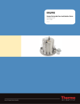
SGD-O
Non-Contacting Density Gauge
For Fracturing & Cementing
User Guide
P/N 717910
Revision D
© 2012 Thermo Fisher Scientific Inc. All rights reserved.
All trademarks are the property of Thermo Fisher Scientific Inc. and its subsidiaries.
Thermo Fisher Scientific Inc. (Thermo Fisher) makes every effort to ensure the accuracy and completeness of this
manual. However, we cannot be responsible for errors, omissions, or any loss of data as the result of errors or
omissions. Thermo Fisher reserves the right to make changes to the manual or improvements to the product at
any time without notice.
The material in this manual is proprietary and cannot be reproduced in any form without expressed written
consent from Thermo Fisher.
This page intentionally left blank.
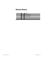
Revision History
Thermo Fisher Scientific
Revision Level
Date
Comments
A
10-2007
Initial release (ERO 5984).
B
04-2008
Revised per ECO 6268.
C
04-2008
Revised per ECO 6298.
D
01-2012
Revised per ECO 7896.
SGD-O User Guide
v
This page intentionally left blank.
Contents
Safety Information .............................................................................................. ix
Safety Considerations ............................................................................. ix
Safety Summary ..................................................................................... ix
Thermo Fisher Scientific
Chapter 1
Product Overview ............................................................................................. 1-1
Introduction........................................................................................ 1-1
The Gamma Source ......................................................................... 1-3
The Detector.................................................................................... 1-4
The Transmitter ............................................................................... 1-4
Inputs & Outputs ............................................................................... 1-5
Output Signals .................................................................................... 1-5
Required Documentation .................................................................... 1-6
Chapter 2
Getting Started................................................................................................... 2-1
Powering the Transmitter.................................................................... 2-1
Interface .............................................................................................. 2-1
The Direct Access Method ............................................................... 2-1
Changing or Viewing Parameters .................................................. 2-2
Issuing Commands........................................................................ 2-2
Chapter 3
Detector Setup & Pre-Calibration ................................................................. 3-1
Procedure ............................................................................................ 3-1
Chapter 4
Gauge Calibration ............................................................................................. 4-1
General ............................................................................................... 4-1
Procedure ............................................................................................ 4-1
Chapter 5
Post Calibration - Setup at the Job Site ....................................................... 5-1
General ............................................................................................... 5-1
Procedure ............................................................................................ 5-1
Chapter 6
The Current Output ............................................................................................ 6-1
Hold the Current Output ................................................................... 6-1
Clear All Holds ................................................................................... 6-2
Check the Input Signal ....................................................................... 6-2
SGD-O User Guide
vii
Contents
viii
SGD-O User Guide
Chapter 7
Adjusting the Gain Settings ............................................................................ 7-1
Overview ............................................................................................. 7-1
Components and Jumpers ................................................................... 7-1
Gain Control Settings ......................................................................... 7-3
Chapter 8
Maintenance ...................................................................................................... 8-1
Overview ............................................................................................. 8-1
Shutter Check ..................................................................................... 8-1
Tag & Label Check ............................................................................. 8-1
Source Housing Check ........................................................................ 8-4
Leak Tests ........................................................................................... 8-4
Chapter 9
Troubleshooting & Service ............................................................................. 9-1
Recovering Memory ............................................................................ 9-1
The Transmitter .................................................................................. 9-2
The Display ..................................................................................... 9-2
The DC Power Fuse......................................................................... 9-2
The Detector....................................................................................... 9-3
The FSU Pre-Amp Board .................................................................... 9-5
Reset Pulse Width Tests ................................................................... 9-7
Gain Test ......................................................................................... 9-8
Disassembly ........................................................................................ 9-8
Contact Information ........................................................................... 9-9
Warranty ........................................................................................... 9-10
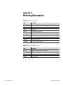
Appendix A
Ordering Information ....................................................................................... A-1
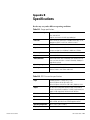
Appendix B
Specifications ................................................................................................... B-1
Appendix C
Calibration Tables ............................................................................................ C-1
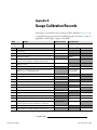
Appendix D
Gauge Calibration Records ............................................................................ D-1
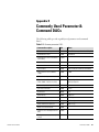
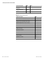
Appendix E
Commonly Used Parameter & Command DACs.......................................... E-1
Appendix F
Toxic & Hazardous Substances Tables ........................................................ F-1
Appendix G
Related Technical Bulletins .......................................................................... G-1
Thermo Fisher Scientific
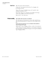
Safety Information
This chapter contains information that must be read and understood by all
persons installing, using, or maintaining this equipment.
Safety
Considerations
Failure to follow appropriate safety procedures or inappropriate use of the
equipment described in this manual can lead to equipment damage or
injury to personnel.
Any person working with or on the equipment described in this manual is
required to evaluate all functions and operations for potential safety hazards
before commencing work. Appropriate precautions must be taken as
necessary to prevent potential damage to equipment or injury to personnel.
The information in this manual is designed to aid personnel to correctly
and safely install, operate, and/or maintain the system described; however,
personnel are still responsible for considering all actions and procedures for
potential hazards or conditions that may not have been anticipated in the
written procedures. If a procedure cannot be performed safely, it must not
be performed until appropriate actions can be taken to ensure the safety
of the equipment and personnel. The procedures in this manual are not
designed to replace or supersede required or common sense safety practices.
All safety warnings listed in any documentation applicable to equipment
and parts used in or with the system described in this manual must be read
and understood prior to working on or with any part of the system.
Failure to correctly perform the instructions and procedures in this
manual or other documents pertaining to this system can result in
equipment malfunction, equipment damage, and/or injury to personnel.
Safety Summary
The following admonitions are used throughout this manual to alert users
to potential hazards or important information. Failure to heed the
warnings and cautions in this manual can lead to injury or equipment
damage.
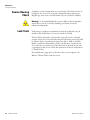
Warning Warnings notify users of procedures, practices, conditions, etc.
which may result in injury or death if not carefully observed or followed.
The triangular icon displayed with a warning may contain a lightning bolt
or the radiation symbol, depending on the type of hazard.
Thermo Fisher Scientific
SGD-O User Guide
ix
Safety Information
Safety Summary
Caution Cautions notify users of operating procedures, practices,
conditions, etc. which may result in equipment damage if not carefully
observed or followed.
Note Notes emphasize important or essential information or a statement of
company policy regarding an operating procedure, practice, condition,
etc.
x
SGD-O User Guide
Thermo Fisher Scientific
Chapter 1
Product Overview
Introduction
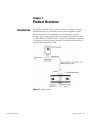
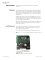
The Thermo Scientific SGD-O system consists of a radiation source in a
lead-filled housing, an ion chamber detector with an amplifier, and the
SGD-O transmitter. The transmitter processes the detector signal to
provide a signal output proportional to the density of the slurry, the mass
of solids added per volume of carrier, or both. This instrument is dedicated
to fracturing operations (fracing); therefore, this manual will describe the
setup for fracing applications only.
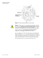
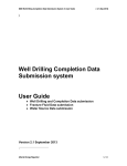
Figure 1–1. Typical system
Thermo Fisher Scientific
SGD-O User Guide
1-1
Product Overview
Introduction
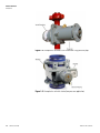
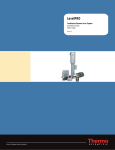
Figure 1–2. Example of a shutterless unit installed on a high pressure pipe
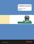
Figure 1–3. Example of a unit with shutter (low pressure application)
1-2
SGD-O User Guide
Thermo Fisher Scientific
Product Overview
Introduction
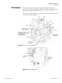
The Gamma Source
The source head contains the gamma source. The gamma radiation is
emitted naturally by a radioactive material. Mostly Cesium-137 (Cs-137) is
used for this application. The radioactive material is first bound in a glass
or ceramic matrix and encapsulated in a stainless steel cylinder that is
welded closed and tested for leakage. This capsule is placed inside another
cylinder of stainless steel that is also welded closed. This double
encapsulation ensures that the source material will remain contained even
under extreme conditions of use. The source capsule is then secured in the
center of the housing.
The radiation hazard of the gauge is minimized by its construction. The
source housing is a rugged, circular steel cylinder that is filled with lead
except in the direction of the beam path. The lead is designed to reduce the
radiation level outside the housing to a relatively low level. The gamma ray
beam is therefore collimated in the direction of the detector.
There are two source housing models primarily used for this application:
Model 5192: This source housing typically does not have a shutter. It is
welded to a high pressure pipe and designed to handle high vibration
applications. For the source head without a shutter, the back of the
detector is designed with extra metal thickness to allow the radiation
beam to be reduced to a safe level outside the detector assembly for
transportation purposes.
Model 5190: This source housing has a sliding shutter with three
positions: ON, OFF, and CAL. The purpose of the shutter is to block
the radiation beam when it is placed in the OFF position.
Due to the precautions taken during manufacture, the chance of leakage is
remote. However, the United States Nuclear Regulatory Commission
(NRC) requires that the source housing be leak tested at regular intervals,
not to exceed three years. Canadian regulations require that leak test
intervals not exceed one year. Refer to the Gamma Radiation Safety Guide
(p/n 717904) for further information. Thermo Fisher is licensed to
perform these tests and can do so through contract services. The first test or
“wipe” is done by licensed personnel or prior to shipment from the factory.
If the source housing is damaged or the system is abandoned, the source
housing must be disposed of properly. Regulations for the NRC, U.S.
Department of Transportation, and the Canadian Nuclear Safety
Commission are continuously being updated; contact Thermo Fisher
Scientific for information on proper source disposal.
Thermo Fisher Scientific
SGD-O User Guide
1-3
Product Overview
Introduction
The Detector
The collimated radiation beam goes through the pipe and process material
where it is attenuated by the slurry. The attenuation is dependent on the
bulk density of the process material. The attenuated beam reaches the
detector on the other side of the pipe where it is measured.
The detector is made of an ion-chamber sensitive to gamma radiation. The
chamber is a small tank filled with pressurized gas. A high voltage is
supplied between the wall of the chamber and a central isolated electrode.
The interaction of the gas and the gamma rays ionizes the gas whose charge
is collected at the central electrode. The output of the ion chamber is
therefore a very small current (picoamp = 10-12 amp) proportional to the
radiation that reaches it. That current is amplified by the detector
electronics to a measurable voltage in the range of 0–10 Vdc. This output
voltage is sent to the transmitter for processing.
The Transmitter
The SGD-O transmitter is a microprocessor-based system that processes
the signal from the detector (0–10 Vdc) to provide an output signal (4–20
mA) representing the amount of solids (proppant) added per volume unit
of carrier and/or the bulk density of the slurry. It monitors system
performance and generates system fault and warning alarms as well.
The integral keypad on the transmitter is normally used as the primary
means of communication with the instrument. Menu selections,
commands, and parameter values are entered using the keypad. The
transmitter has a four-line display that shows either one menu item or up
to eight readouts in alternation (four at a time).
An RS232 serial port can also be used to communicate with the instrument
using a PC with terminal emulation software.
1-4
SGD-O User Guide
Thermo Fisher Scientific
Product Overview
Inputs & Outputs
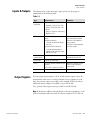
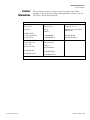
Inputs & Outputs
The characteristics of the input and output options for the gauge are
summarized in the following table.
Table 1–1.
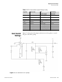
Output Signals
Type
Characteristics
Comments
Transmitter
input power
DC power:
Standard: 12 Vdc (9–15 V), 15 W
Optional: 24 Vdc (20–28 V), 12 W
AC power:
Optional: 110/220 Vac (100–240 V),
50/60 Hz, 25 VA
Current output
3.8–20.5 mA DC (adjustable operating
range)
Standard configuration:
- Isolated, self-powered, 700 ohm
max. load
Alternate optional configuration:
- Isolated, loop-powered (usersupplied 24 Vdc loop power input),
700 ohm max. load
Default range is 4–20 mA dc.
One current output standard.
Maximum of two additional
current outputs.
Configure as loop-powered by
removing a jumper.
Serial
communications
RS232: 1 terminal block
Full duplex communication
with remote terminal or PC.
Current input
4–20 mA DC current input
Relays
Two relays optionally available on each
I/O board
Form C SPDT, isolated, 8 A, 220 Vac
Maximum of 6 relays. Process
alarms can be assigned to
control relays.
Display
4-line, backlit LCD
English language setup menus.
You can assign measurements to the 4–20 mA current output or have the
measurement values sent to a remote terminal or host computer as serial
data. One current output is provided on the standard I/O board, and two
additional current outputs are available (one per I/O board).
Two optional relay outputs can be provided on each I/O board.
Note If the detector will be connected directly to customer equipment (i.e. the
SGD-O transmitter will not be used), the detector output is 0 to 10 Vdc.
Thermo Fisher Scientific
SGD-O User Guide
1-5
Product Overview
Required Documentation
Required
Documentation
1-6
SGD-O User Guide
In addition to this guide, the following documents must be read and
understood by all persons installing, using, or maintaining this equipment:
SGD-O Installation Guide (p/n 717913)
Gamma Radiation Safety Guide (p/n 717904)
Thermo Fisher Scientific
Chapter 2
Getting Started
Powering the
Transmitter
There are three input power options for the SGD-O transmitter:
●
12 Vdc version (standard)
●
24 Vdc (optional)
●
115/230 Vac (optional)
The transmitter power cable is configured to operate the 12 Vdc version
only. In order to use the power cord for 24 Vdc or 115/230 Vac,
modification to the power cord is required. This procedure is described in
the SGD-O installation guide.
Caution Before setting up or calibrating the gauge, verify that proper input
voltage is being supplied to the transmitter. Also verify the power cord is
configured properly for the required power input.
Interface
The Direct Access
Method
With the direct access method, users input codes for parameters that need
to be changed or codes to issue commands to the transmitter. This method
allows you to bypass the menu structure and directly access a specific menu
item. In order to use the direct access method, you must know the direct
access code (DAC or the keypad code) for the desired parameter or
command. The parameter DACs have six digits, and the command DACs
have one, two, or three digits. Appendix E provides a list of commonly
used parameter and command DACs.
Note This manual provides instructions using the direct access method, as
it is a more efficient way to access menu items.
Thermo Fisher Scientific
SGD-O User Guide
2-1
Getting Started
Interface
Changing or Viewing
Parameters
This section will show you how to change a parameter using the direct
access method. In this example, change the value of the time constant. The
DAC for the time constant parameter is 007004.
1. Press: EXIT SETUP, 007004, down arrow.
2. To leave the value as is, press EXIT SETUP, and the gauge will return
to its normal display mode.
To change the value, enter the new value, and press the down arrow,
EXIT SETUP. The gauge will begin using the new value immediately
and will return to normal display mode.
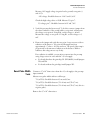
Issuing Commands
This section will show you how to issue commands using the direct access
method. In this example, force the current output to 20 mA. The
command code is 5.
1. Press: EXIT SETUP, 5, down arrow.
2. The display shows two options. Press the left arrow to reject the
command or the right arrow to execute it.
2-2
SGD-O User Guide
Thermo Fisher Scientific
Chapter 3
Detector Setup & Pre-Calibration
Procedure
For best performance, the detector must be adjusted for maximum signal
on empty pipe. To do this, the unit must be connected to the transmitter
and power applied.
Note There must not be any other nuclear sources within 10 feet of the
unit being set up and calibrated.
1. If the radioactive source has a shutter assembly, verify that it is in the
ON position (shutter is open). If it is a high-pressure unit, the source
will not have a shutter, and you can skip this step.
2. Remove the lid of the detector housing. Set it aside, leaving the wiring
from the lid to the detector connected.
3. Verify that the J1 connector is running parallel with the pipe that the
gauge is mounted on. This will orient the reed switch for proper
operation. Also verify that the hold down bolt is tightened properly.
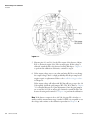
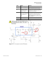
4. Refer to Figure 3–1. Use a voltmeter to verify that the +15 Vdc (pin 4
of J1) and -15 Vdc (pin 1 of J1) (power ground – pin 5 of J1) are there
and within ± 0.5 Vdc of specified voltage. If one or both of the voltages
are incorrect or not there at all, either the transmitter to detector cable
is bad or the transmitter is not outputting the ±15 Vdc properly.
Thermo Fisher Scientific
SGD-O User Guide
3-1
Detector Setup & Pre-Calibration
Procedure
Figure 3–1.
5. Measure pins 2(-) and 3(+) for the Vdc output of the detector. Adjust
R35 to obtain an output of 9.6 Vdc on empty pipe. If this voltage is
achieved, attach the lid to the detector housing and skip to Chapter 4
to perform the calibration. Otherwise, continue to step 6.
6. If the output voltage stays at one value and using R35 does not change
the output voltage, there is a high probability that the pre-amp board
requires repair or replacement. Refer to the troubleshooting procedure
in Chapter 9.
If the output voltage will adjust with R35 but will not get up to the 9.6
Vdc required, check the gain jumpers (W1, W2, W3). Refer to Chapter
7 for a detailed discussion of gain adjustments. Once the gain jumpers
are set and the 9.6 Vdc on empty pipe obtained, reattach the lid to the
detector housing and continue to Chapter 4 to perform the calibration.
Note If the detector output is above 8.0 Vdc, the pipe ID is 6 inches or
smaller, and the measurement range is under 10 PPA, it is acceptable to use
the voltage and continue to the calibration procedure in Chapter 4.
3-2
SGD-O User Guide
Thermo Fisher Scientific
Chapter 4
Gauge Calibration
General
Procedure
For optimum performance, calibrate the gauge exactly as described below.
It is assumed that the gauge has been installed properly, the shutter is open
(if applicable), the pipe is empty of any fluid, and that the SGD-O
transmitter is being used.
A condensed version of this procedure can be found in Appendix D. The
appendix also provides space to record values.
Note Reference Chapter 2 for instructions on how to use a direct access
code (DAC).
1. Erase memory (DAC 74). This step is necessary to ensure that all data
is reset to factory defaults.
2. Load the standard oilfield setup into transmitter memory (DAC 1016).
After loading the setup, the top line of the display will be Measurement
1, which is lbs/Usg SolAdd. {This unit is equal to today’s PPA (pounds
of proppant added) per US gallon of carrier fluid. The measurement
may have also been in PSA (pounds of sand added), which is pounds of
proppant added per gallon of carrier fluid pumped.}
The second line of the display will show the bulk density in lb/US Gal,
and the third line will show the bulk density in g/ml.
3. Enter the pipe ID in inches (DAC 048003). It is important this value
be as accurate as possible.
Caution Once the pipe ID is entered, do not change it, even if the entry is
incorrect. Changing the value after calibration is performed will invalidate
the calibration.
Thermo Fisher Scientific
SGD-O User Guide
4-1
Gauge Calibration
Procedure
4. To determine the water/air ratio, first standardize the gauge with pipe
full of air using (DAC 121). When finished, fill the pipe full of water
and allow the detector to stabilize for approximately five minutes.
5. Calibrate the gauge with pipe full of water (DAC 4). This will result in
the second half of the water/air ratio. When finished, leave the pipe full
of water.
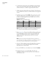
6. Recall the water/air ratio (DAC 118003). The water/air ratio is used to
obtain the calibration factor in the next step. Based on the setting of
9.6 Vdc on air and the pipe ID, the ratio should be close to the ones
listed in the table below.
Figure 4–1. Pipe IDs and water/air ratios
Pipe ID
Ratio
Pipe ID
Ratio
2”
0.75
6”
0.375
3”
0.625
8”
0.25
4”
0.5
10”
0.125
Note If the ratio is not near the one shown for your pipe ID, then an
error occurred. Stop the calibration process and start again.
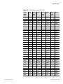
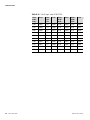
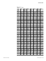
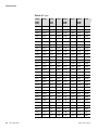
7. Refer to Appendix C. There are four calibration tables grouped by pipe
ID. Using the pipe ID and the water/air ratio, locate the factor and
record it. The calibration factor is used to calculate the ZnCl (zinc
chloride) value used to obtain the slope correction for a 2-point
calibration curve.
Note If your ratio is between 0.98 and 1.00, there was either air or
water in the pipe for both the standardization and calibration cycles. If
this is the case, stop the calibration process and start again.
8. Clear the “Cal Point Pending” message (DAC 49). When you return to
the main screen, the alarm will still be displayed. Press the EXIT
SETUP key twice to clear the alarm.
9. Reset the CAL/REF ratio to the default value of 1.000 (DAC 086003).
10. Standardize the gauge on water (DAC 121). This will set the
standardization value (water value) that will be used to calculate the
ZnCl calibration value.
4-2
SGD-O User Guide
Thermo Fisher Scientific
Gauge Calibration
Procedure
11. When standardization is complete, recall the water signal value (DAC
128003). Record this value.
Note The water signal value will be displayed with E4 at the end of it.
The calculation in the next step will be easier using a whole number.
To record this value as a whole number, move the decimal to the right
four places. For example, 3.123E4 is 31230.
12. Calculate the ZnCl signal:
ZnCl Value = Water Signal from step 11 × Factor from step 7
For example, if the factor obtained in step 7 is 0.5077 and the water
signal value from step 11 is 31230, then:
ZnCl Value = 31230 × 0.5077 = 15855
13. Enter the calculated ZnCl value calculated in step 12 into memory
(DAC 133003).
Note Values in scientific notation (values greater than 99999) must be
entered differently. Enter the base first. Then press the decimal key to
bring up the E, which indicates the start of the exponent. Enter the
exponent.
14. Hold the output at the ZnCl signal value (DAC 137). The displayed
values will change.
15. Observe the process g/ml value on the third line of the display. It
should be near 1.812 g/ml. If it is below 1.6 or above 2.0 g/ml, it is
likely that an error occurred. Repeat this procedure.
16. Recall the density slope correction factor (DAC 049003). Record this
value.
17. Recall the carrier specific gravity (DAC 085003). Record this value.
Note The values recorded in steps 16 and 17 are required for
troubleshooting purposes. Keep these values handy.
Thermo Fisher Scientific
SGD-O User Guide
4-3
Gauge Calibration
Procedure
18. With the ZnCl hold active, check the third line of the display. Exactly
1.812 g/ml should be displayed.
Adjust the density slope correction factor if necessary (DAC 049003).
Return to the main screen. The display will update in approximately
three seconds. If the displayed value is not 1.812 g/ml, observe how far
off the value is. Make another adjustment to the slope correction factor
(DAC 049003). Return to the main screen and wait for the screen to
update. Repeat this process until the third line of the display is exactly
1.812 g/ml.
19. Clear the ZnCl hold (DAC 9). This will return the gauge to normal
operation.
20. The displayed density should then be 1.000 g/ml.
The gauge is now calibrated for use of water as the carrier.
Note This calibration will be valid as long as the detector is not moved or
removed from the housing.
4-4
SGD-O User Guide
Thermo Fisher Scientific
Chapter 5
Post Calibration - Setup at the Job
Site
General
Procedure
This procedure assumes that you have completed the pre-calibration
procedures in Chapter 3 and the calibration procedures in Chapter 4.
Once the SGD-O gauge is in service, one more operation is necessary for
proper indication of the Pounds of Sand Added and the Pounds per Gallon
indications of the gauge.
Note Reference Chapter 2 for instructions on how to use a DAC.
1. Allow carrier fluid into the pipe that the gauge is mounted on. Let the
indication stabilize, and record the density value (g/ml) shown on the
third line of the gauge display.
2. Recall the carrier specific gravity (DAC 085003). Record the value that
is displayed. (This is the value used during calibration, and you will
need to re-enter this value when the current pumping job is finished.)
Enter the value recorded in step 1. Press the down arrow and then
EXIT SETUP.
3. View the detector signal (DAC 112003). Observe the value for several
seconds to obtain an average and record it. Press EXIT SETUP twice
and enter 128003.
Enter the value you just recorded (from 112003). To enter a value in
scientific notation, enter the base first. Then press the decimal key to
bring up the E, which indicates the start of the exponent, and then
enter the exponent.
Note that this step can also be done by performing a standardization on
the fluid at this point in the procedure (DAC 121).
Thermo Fisher Scientific
SGD-O User Guide
5-1
Post Calibration - Setup at the Job Site
Procedure
Your gauge is now fully calibrated and ready to use. Both the Pounds of
Sand Added and the Pounds per Gallon indications will be correct.
When the job is finished, return the carrier density to its original value
(DAC 085003). To prepare for the next job, perform a standardization on
a pipe full of clean water (DAC 121).
5-2
SGD-O User Guide
Thermo Fisher Scientific
Chapter 6
The Current Output
Hold the Current
Output
The standard 4–20 mA output can be adjusted so the control room and
local display readings are identical. In order to do this and to check the
connection, hold commands will be used to set the current output to
known value.
Note Reference Chapter 2 for instructions on how to use a DAC.
1. Hold the current output at 4 mA (DAC 8).
If the value is not 4 mA after executing this command, you can apply a
correction factor. First, determine the correction factor by dividing the
new value by the initial value. For example, if the current output is
3.98 mA, divide 4.0 by 3.98:
4.0/3.98 = 1.005.
In this case, the correction factor is 1.005. Enter the correction factor
(DAC 053013).
Note The initial value in this formula is the measured value of the 4 mA
output when the correction factor is equal to 1.0.
2. Hold the current output at 20 mA (DAC 5).
If the value is not 20 mA after executing this command, you can apply
a correction factor. First, determine the correction factor by dividing
the new value by the initial value. For example, if the current output is
20.04 mA, divide 20.0 by 20.04:
20.0/20.04 = 0.998.
In this case, the correction factor is 0.998. Enter the correction factor
(DAC 052013).
Note The initial value in this formula is the measured value of the 20 mA
output when the correction factor is equal to 1.0.
3. Hold the current output at 12 mA (DAC 2).
Thermo Fisher Scientific
SGD-O User Guide
6-1
The Current Output
Clear All Holds
6-2
Clear All Holds
Use the Clear All Holds command (DAC 9) to return the current output
to its normal operation.
Check the Input
Signal
The output of the detector (input to the transmitter) is a voltage signal
0–10 Vdc maximum. Read the signal (DAC 112003). The value is
displayed in scientific notation and represents a range of 0 to 10 volts with
the numbers 0 to 6.554E4 (65540).
SGD-O User Guide
Thermo Fisher Scientific
Chapter 7
Adjusting the Gain Settings
Overview
Users of the SGD-O density gauge often move the detector assembly from
application to application. Among these different applications are variations
in sizes and schedules of pipes, as well as activity and ages of radioactive
sources. The gauge’s hardware gain settings are set for a particular
application; thus, it may be necessary to change certain jumpers or
components to set the detector within its allowable voltage range for the
current application.
This chapter explains how to set the gain values for the Fast Start Unit
(FSU) pre-amp board so that it can be used in different applications
without having to return it to the factory for modification.
Note This chapter applies to the SGD-O FSU pre-amp board 885623 at
revision F or later.
Note Before proceeding, verify that the R1 and R28 factory adjustments
have not been altered. If those adjustments are not set correctly, the gain
circuit will not function correctly. Reference the FSU troubleshooting
procedure in Chapter 9.
Components and
Jumpers
Warning Ensure that power is off and the area is non-hazardous before
making any of the adjustments described in this document.
The R35 potentiometer (pot) is a fine tuning pot only. It was never
intended to be a full-scale adjustment. Therefore, if you cannot get the
detector output up to 9.6 Vdc by adjusting the R35 pot, with air in the
pipe, the hardware gain will have to be modified. A number of components
and jumpers on the pre-amp board can be adjusted in such instances.
Specifically, these are components C13, R5, R36, R37 and wire jumpers
W1, W2, and W3. See Figure 7–1.
Thermo Fisher Scientific
SGD-O User Guide
7-1
Adjusting the Gain Settings
Components and Jumpers
Figure 7–1. FSU pre-amp board components and gain jumpers
Caution The C13 capacitor is located under the metal shield on the FSU
pre-amp board. Everything under this shield is high impedance circuitry.
Do not touch anything under the shield with bare hands! If any of these
components are contaminated, the detector signal will fluctuate, making
the detector ineffective. Use only clean metal tools to touch these
components. Do not apply any kind of cleaner to them.
For most applications, the value of the C13 capacitor is normally 330 pF.
However, as shown in Table 7–1, the value of C13 can also be 220 pF or
470 pF, depending on the application for which the detector was originally
purchased. A 220 pF capacitor will make the gain higher and a 470 pF
capacitor will make the gain lower. If you are having trouble getting the
gain either high enough or low enough, check the value of C13.
7-2
SGD-O User Guide
Thermo Fisher Scientific
Adjusting the Gain Settings
Gain Control Settings
Table 7–1. FSU setup to obtain required voltage reading
Gain Control
Settings
Pipe Size
Source Size
C13
(Default 330 pF)
Gain Setting
(Default 1X)
2” HP
100 mCi
330 or 470 pF
1X or 2X
2” HP
145 mCi
330 or 470 pF
1X
2” HP
200 mCi
330, 470, or 680 pF
1X
3” HP
200 mCi
330 pF
1X
4” HP LP
200 mCi
330 or 470 pF
1X or 2X
6” LP
200 mCi
330 or 470 pF
2X
8” LP
200 mCi
220 or 330 pF
2X
10” LP
200 mCi
220, 330, or 470 pF
2X or 3X
Figure 7–2 shows how the jumpers and resistors work together to control
the gain of the AR1 op-amp.
Figure 7–2. Gain control of the AR1 op-amp
Thermo Fisher Scientific
SGD-O User Guide
7-3
Adjusting the Gain Settings
Gain Control Settings
The gain settings listed in Table 7–2 are based on the following component
values being installed on the FSU pre-amp board.
●
R5 = 49.9 kohm, 1% precision
●
R36 = 8.25 kohm, 1% precision
●
R37 = 49.9 kohm, 1% precision
●
C13 = 330 pF
Note On the three solder points of the W1/W2 jumper points, the center
point is the common. Therefore, the wire jumper goes from the center
point up to the 1 point for the W1 jumper or from the center point down
to the 2 point for the W2 jumper.
Install the proper gain components until the R35 pot will adjust the voltage
output of the detector, with air in the pipe, to 9.6 Vdc. As an example, the
R35 pot should adjust the voltage out from 10 Vdc to approximately 8.0
Vdc. If the R35 pot will only adjust the detector output from 4.0 to 5.0
Vdc, you will need to double the gain.
If you are already on the lowest gain and the voltage will not go down, the
factory pot settings may have been changed. Verify the R1 and R28 factory
settings.
Changing C13 will move the entire gain curve either up or down
depending on the capacitor used. Figure 7–3 shows the relationship C13
has in the control circuit of the FSU detector.
Table 7–2. Gain settings
7-4
SGD-O User Guide
Times
Setting
Comment
Unity gain
(no gain)
No jumpers
This may be necessary on 3” or 4” pipes with
newer sources to prevent saturating the
detector.
X1
W1 jumper
This is the normal setting and adds a preset
amount of gain to the circuit over the unity gain
(no jumper) setting.
X1.5
W1 jumper + W3 jumper +
R36 changed to 49.9 kohm
The W1 jumper puts R5, R37 in parallel with
W3 installed. Changing R36 changes the current
of the feedback loop to the op-amp.
X2
W2 jumper
This leaves the W5 leg at 49.9K but puts R37
into the feedback loop, changing the current to
the op-amp.
X3
W2 jumper + W3 jumper +
R36 changed to 49.9 kohm
This leaves the W5 leg at 49.9K and puts R36
and R37 in parallel, changing the current to the
op-amp.
Thermo Fisher Scientific
Adjusting the Gain Settings
Gain Control Settings
Times
Setting
Comment
X4
W1 jumper + W3 jumper
This parallels R5 and R37 and adds R36 to the
circuit, changing the current to the op-amp.
X5
W2 jumper + 8.25 kohm
resistor used as W3 jumper,
instead of the wire
Using the resistor instead of the wire provides
more versatility to adjusting the current in the
feedback loop to the op-amp.
X6
W2 jumper + 8.25 kohm
resistor used as W3 jumper
+ R36 changed to 4.12
kohm
Using the resistor instead of the wire provides
more versatility to adjusting the current in the
feedback loop to the op-amp. An 8.25 kohm
resistor soldered parallel onto R36 will change
R36 to 4.12 kohm.
X7
W3
Everything else remains at default values.
X8
W2 jumper + W3 jumper
Everything else remains at default values.
Figure 7–3. C13 in the control circuit of the FSU detector
Thermo Fisher Scientific
SGD-O User Guide
7-5
This page intentionally left blank.
Chapter 8
Maintenance
Overview
The SGD-O is fairly maintenance free, but you should follow the schedule
below to remain in compliance. The tasks are described in further detail in
the sections that follow.
Table 8–1. Maintenance schedule
Shutter Check
Task
Interval
Complete a shutter check (if the system
has a shutter).
Every 6 months.
Complete a tag check.
Every 6 months.
Complete a source housing check.
Every 6 months.
Complete a leak test.
Every 36 months for U.S. or every 12 months for
Canadian installations.
If your system has a shutter, complete a shutter check every six months.
The shutter check consists of the following two steps.
1. Slide the shutter to each position to make sure it functions properly.
2. Visually inspect the shutter, ensuring it has not been damaged and that
all of the lead plates are in place.
Tag & Label
Check
Complete a tag and label check every six months. All labels and tags
attached to the source must be visible per radiation safety standards. All
labels and tags must be securely attached and legible (including engraved
labeling). Immediately replace any label that is damaged, illegible, or not
securely attached.
Do NOT paint or overcoat the source housing without first masking the
radiation identification tag and other labeling.
Below are examples of the tags and labels that may be a part of your system.
Thermo Fisher Scientific
SGD-O User Guide
8-1
Maintenance
Tag & Label Check
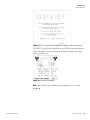
Figure 8–1. Source identification tag example
Figure 8–2. DOT 7A Type A label with General License information
The DOT 7A Type A label example above (p/n 702272) provides General
License information and is only used on instruments going to customers
with a General License.
8-2
SGD-O User Guide
Thermo Fisher Scientific
Maintenance
Tag & Label Check
Figure 8–3. DOT 7A Type A label example with Specific License information
The DOT 7A Type A label example above (p/n 700192) provides Specific
License information and is only used on instruments going to customers
with a Specific License.
Figure 8–4. Caution tag example
Note None of these tags should be removed, painted over, or remain
illegible.
Thermo Fisher Scientific
SGD-O User Guide
8-3
Maintenance
Source Housing Check
Source Housing
Check
Complete a source housing check every six months. This check consists of
looking for rust, corrosion, worn parts, damaged housing, missing tags,
illegible tags, and a worn or broken shutter (if your system has a shutter).
Warning Use a long handled brush to remove debris in the beam path to
ensure that no part of your body, including your hands, enters the
radiation beam path.
Leak Tests
Leak testing is a regulatory requirement. It must be completed every 36
months in the United States or every 12 months in Canada.
Thermo Fisher is licensed to perform these tests and can do so through
contract services. If you are currently using the leak testing service provided
by Thermo Fisher or purchased the gauge after July 1, 2006, you will be
mailed a notification letter 60 days prior to the due date of your leak test.
Two weeks later you will receive your leak test kit in the mail. If you wish
to participate in this service, follow the instructions in the kit, and return it
to Thermo Fisher.
If you purchased a gauge prior to the above date, you can request to be
added to Thermo Fisher’s leak test service.
8-4
SGD-O User Guide
Thermo Fisher Scientific
Chapter 9
Troubleshooting & Service
Recovering
Memory
If the memory or instrument calibration has been lost but the detector and
electronics are still functional, follow the procedure below to recover
memory.
Note This procedure assumes that the SGD-O gauge was fully calibrated
as described in this manual and that the water standardization value and
slope correction value were recorded from the last calibration. If these two
values are not available, it is not possible to perform this procedure.
Note Reference Chapter 2 for instructions on how to use a DAC.
1. Erase memory (DAC 74).
2. Load the oilfield setup (DAC 1016).
3. Enter the pipe ID (DAC 048003).
4. Run the standardization cycle (DAC 121). (Ignore what is in the pipe.
This was done to set command flags in memory.)
5.
Enter the water value recorded during the last calibration (DAC
128003).
6. Enter the slope correction value recorded from the last calibration
(DAC 049003).
The gauge will now be in the condition it was when brought to the job site.
Any changes made to the instrument at the job site should be done now.
Thermo Fisher Scientific
SGD-O User Guide
9-1
Troubleshooting & Service
The Transmitter
The Transmitter
The Display
This section provides troubleshooting procedures for the SGD-O
transmitter.
The instrument sends continuous readouts to the display. If the display is
blank, the readout is dim, or the readout displays in a yellow-green color,
increase the contrast by pressing the up arrow on the transmitter keypad.
If the display consists of dark rectangles, decrease the contrast by pressing
the down arrow.
If adjusting the contrast does not correct the display problem, first verify
the power supply at the source. If this is not the problem, remove power
from the transmitter. Open the enclosure and verify that the keypad cable
is properly installed on the CPU board.
If transmitter still does not display, the CPU board may be malfunctioning.
Refer to the SGD-O installation manual for instructions on replacing
boards in the transmitter.
The DC Power Fuse
If you suspect a problem with the DC power fuse, power down the unit
and measure the resistance with a multimeter. If the fuse is good, the
reading will be approximately 0 ohms.
You can also look at the fuse and determine it is bad if it looks brown.
Note See Figure 9–1. If you are using a 12 Vdc board, the fuse is at F2.
Figure 9–1. DC power fuses on the I/O relay board
9-2
SGD-O User Guide
Thermo Fisher Scientific
Troubleshooting & Service
The Detector
The Detector
This section provides a procedure for general troubleshooting of the
detector. If you suspect a problem with the pre-amp board specifically, also
follow the procedure in the next section, “The FSU Pre-Amp Board.”
The locations of the components and jumpers referenced in this procedure
are shown in the figures below.
Figure 9–2. SGD-O FSU pre-amp board
Figure 9–3. Power supply board
Thermo Fisher Scientific
SGD-O User Guide
9-3
Troubleshooting & Service
The Detector
1. Check the detector signal by entering DAC 112003 at the transmitter.
If the detector is set to 9.6 Vdc on air, the value should be
approximately 6.311E4.
If the value shown is 6.542E4, the detector signal is over 10 Vdc and
the detector will not work. If the value shown is less than 6.200E4,
then the detector gain is not set correctly or the detector is
malfunctioning. Refer to Chapter 7 to adjust the gain settings.
2. Remove the detector lid. Use a voltmeter to measure the voltage from
pin 1 to pin 4 of J1 on the pre-amp board. Pin 1 is the pin furthest
from the edge of the board. The reading should be approximately 30
Vdc. If it is, both the +15 Vdc and -15 Vdc are coming from the
transmitter and reaching the detector.
If the voltage is only 15 Vdc, then one of the 15 Vdc supplies is not
reaching the detector. If the voltage is zero, then neither 15 Vdc
supplies are reaching the detector. Check cabling and the output of the
transmitter VPI board.
3. Measure pin 2 to pin 3 of J1. This is the output of the detector. It
should be 9.6 Vdc with air in the pipe.
If the output is 9.6 Vdc ±3.0 volts, use the R35 potentiometer on the
pre-amp board to adjust the output to 9.6 Vdc with air in the pipe.
If the output is above 10 Vdc and will not adjust, verify the gain
jumper is on W1 and the W3 jumper is not installed. If necessary,
modify these jumpers.
With the gain jumper on W1 and W3 not installed, fill the pipe with
water and see if the voltage drops below 10 Vdc. If it does not, the preamp board requires repair or replacement.
4. If the output voltage does drop below 10 Vdc when the pipe is filled
with water, then the gain is set too high. Remove the W1 jumper
completely and the gain will lower to the point that you should be able
to use R35 to adjust the output to 9.6 Vdc on a pipe full of air.
If the output voltage can be adjusted with the R35 pot, but will not
increase to the 9.6 Vdc, on a pipe full of air, then the gain is set too
low. Move the W1 jumper to W2 (keeping in mind that the center
hole is the common connection). In most cases, you should now be
able to use the R35 pot to adjust the output to 9.6 Vdc on air.
9-4
SGD-O User Guide
Thermo Fisher Scientific
Troubleshooting & Service
The FSU Pre-Amp Board
If the output voltage is very low and using the R35 pot will only adjust
the output approximately 0.5 to 1.0 Vdc, check the R5 resistor on the
pre-amp board. If it is a 49.9 kohm resistor, replace it with an 8 kohm
resistor. Doing this should raise the gain enough to obtain the 9.6 Vdc
output with air in the pipe. If it does not, it is like the pre-amp requires
repair or replacement.
5. If you suspect the pre-amp board is bad, check the factory settings on
the board. Continue to the next section.
Note If you purchased a pre-amp board (p/n 885623) by itself as a spare
part, the R1 and R28 pots have not been set. In this case, it is necessary to
follow the procedure in the next section so the pre-amp board will operate
properly.
6. With power applied to the pre-amp board, connect a wire jumper from
the center conductor coaxial cable to test point 6. Measure the voltage
at test point 6 and use the R28 pot to set this voltage to -80 mV.
Measure the Vdc on test point 1 and use the R1 pot to set this voltage
to +5 mV.
The FSU PreAmp Board
This section provides a procedure for troubleshooting the SGD-O FSU
pre-amp board (p/n 885623). The procedure will aid technical personnel in
determining if suspected problems with the pre-amp board are simple
calibration issues that can be resolved with adjustment of the
potentiometers on the board or actual component failures that require the
board be replaced or returned to the factory for repair.
Two Hi-Meg resistors are required. They are listed below with the Thermo
Fisher Scientific part numbers.
●
4.7 x 10⁹ ohm resistor, p/n 351760
●
4.7 x 10¹⁰ ohm resistor, p/n 351810
Note If you purchased a pre-amp board (p/n 885623) by itself as a spare
part, the R1 and R28 pots have not been set. In this case, it is necessary to
follow this procedure so the pre-amp board will operate properly.
The locations of the components and jumpers referenced in this procedure
are shown in Figure 9–2 and Figure 9–3.
Thermo Fisher Scientific
SGD-O User Guide
9-5
Troubleshooting & Service
The FSU Pre-Amp Board
Caution The C13 capacitor is located under the metal shield on the FSU
pre-amp board. Everything under this shield is high impedance circuitry.
Do not touch anything under the shield with bare hands! If any of these
components are contaminated, the detector signal will fluctuate, making
the detector ineffective. Use only clean metal tools to touch these
components. Do not apply any kind of cleaner to them.
1. Check the FSU detector power supply voltages.
There are + 15 and - 15 volt supplies on the pre-amp board coming
from the power supply in the panel. Test points are provided for both
supplies near J2. The ground test point is near J1. R10 and R11 on the
pre-amp are 10-ohm resistors that are in series with the -15 and +15
volt supplies.
The voltage drops across these two resistors are listed below. There is
also a +12 volt regulator on the pre-amp board. This voltage can be
checked on the positive side of C21.
Measure + 15V and - 15V supply current tap voltages:
+15V: Voltage drop across R11 should be between 80 mV and 220 mV.
-15V: Voltage drop across R10 should be between 40 mV and 150 mV.
Measure +12V at positive (+) side of C21:
+12V voltage: Should be between 11.0 V and 13.0 V.
2. Check the high voltage on the power supply board. It should be
between 1300 Vdc and 1600 Vdc. This voltage can be measured on the
ion chamber.
There are +15 and - 15 volt supplies on the high voltage power supply
board coming from the power supply in the panel. R1 and R3 on the
high voltage power supply board are 10-ohm resistors that are in series
with the -15 and +15 volt supplies.
The voltage drops across these two resistors are listed below. There is a
-12 volt regulator on the power supply board. This voltage can be
checked on the negative side of C3. The ground point is on the
bottom end of CR3 nearest U3.
Measure +15V and -15V supply current tap voltages:
+15V current: Voltage drop across R1 should be between 130 mV
and 280 mV.
-15V current: Voltage drop across R3 should be between 130 mV
and 280 mV.
9-6
SGD-O User Guide
Thermo Fisher Scientific
Troubleshooting & Service
The FSU Pre-Amp Board
Measure -12V supply voltage (negative lead to ground) at negative (-)
end of C3:
-12V voltage: Should be between -11.0 V and -13.0 V.
Check the high voltage drive on U3B. Measure U3, pin 7:
U3 voltage, pin 7: Should be between 0.0 V and 7.0 V.
3. Verify the pre-amp has been zeroed. To do this, connect a jumper from
the center conductor of the coaxial cable to test point 6, and measure
the voltage at test point 6. Using R28, set this voltage to -80 mV.
Measure the voltage on test point 1. Using R1, set this voltage to +5
mV.
4. Remove the jumper and verify that test point 1 stays near zero with no
radiation on the detector. Test point 6 will ramp down from
approximately +7 volts to -10 volts and reset. The speed of the ramp is
proportional to the amount of radiation on the detector. With no
radiation, this voltage moves very slowly.
If no radiation is available, you can inject a current into the pre-amp
using a large resistor in series with the +15 volt supply.
●
●
Reset Pulse Width
Tests
For boards that have the gain chip U2 (LF13006N), install jumpers
W3 and W4.
For boards without the gain chip, install jumper W1.
Connect a 4.7 x 10⁹ ohm resistor from the +15 volt supply to the pre-amp
input terminal.
Measure reset pulse widths with an oscilloscope:
T1 (at TP4): Should be between 25 ms and 65 ms.
T2 (at TP3): Should be between (T1+14 ms) and (T1+37 ms).
T3 (at TP2): Should be between (T1+14 ms) and (T1+37 ms) (this is a
negative pulse).
Remove the 4.7 x 10⁹ ohm resistor.
Thermo Fisher Scientific
SGD-O User Guide
9-7
Troubleshooting & Service
Disassembly
Gain Test
Allow 24 seconds on this measurement.
Connect a 4.7 x 10¹⁰ ohm resistor from the +15 volt supply to the
pre-amp input terminal.
Measure TP1 voltage. It should be between 3.9 V and 4.6 V, with
optimum measurement at 4.2 V.
The absolute voltage is not as important as the stability of the voltage.
Variance after stabilization must be less than 10 mV.
Remove the 4.7 x 10¹⁰ ohm resistor.
Disassembly
Disassembly of the instrument is not allowed.
The only exception to this statement is for those with a Specific License
that contains special permission to separate the source housing from the
pipe.
Persons with a General License are never allowed to disassemble the
source housing from the pipe.
Additionally, the Type A shipping certificate is issued to the instrument as
a single component consisting of the detector, source housing, and pipe. If
the source housing is separated from the pipe, it is no longer covered by the
Type A shipping certificate.
9-8
SGD-O User Guide
Thermo Fisher Scientific
Troubleshooting & Service
Contact Information
Contact
Information
The local representative is your first contact for support and is well
equipped to answer questions and provide application assistance. You can
also contact Thermo Fisher directly.
Process Instruments
14 Gormley Industrial Avenue
Gormley, Ontario
L0H 1G0
CANADA
Unit 702-715, 7/F Tower West
Yonghe Plaza No. 28
Andingmen East Street, Beijing
100007 CHINA
+1 (800) 437-7979
+1 (713) 272-0404 direct
+1 (713) 4573 fax
+1 (905) 888-8808
+1 (905) 888-8828 fax
+86 (10) 8419-3588
+86 (10) 8419-3580 fax
A-101, 1CC Trade Tower
Senapati Bapat Road
Pune 411 016
Maharashtra, INDIA
Ion Path, Road Three
Winsford, Cheshire
CW7 3GA
UNITED KINGDOM
1410 Gillingham Lane
Sugar Land, TX
77478 USA
+91 (20) 6626 7000
+91 (20) 6626 7001 fax
+44 (0) 1606 548700
+44 (0) 1606 548711 fax
www.thermoscientific.com
Thermo Fisher Scientific
SGD-O User Guide
9-9
Troubleshooting & Service
Warranty
Warranty
Thermo Scientific products are warranted to be free from defects in
material and workmanship at the time of shipment and for one year
thereafter. Any claimed defects in Thermo Scientific products must be
reported within the warranty period. Thermo Fisher shall have the right to
inspect such products at Buyer’s plant or to require Buyer to return such
products to Thermo Fisher plant.
In the event Thermo Fisher requests return of its products, Buyer shall ship
with transportation charges paid by the Buyer to Thermo Fisher plant.
Shipment of repaired or replacement goods from Thermo Fisher plant shall
be F.O.B. Thermo Fisher plant. A quotation of proposed work will be sent
to the customer. Thermo Fisher shall be liable only to replace or repair, at
its option, free of charge, products which are found by Thermo Fisher to be
defective in material or workmanship, and which are reported to Thermo
Fisher within the warranty period as provided above. This right to
replacement shall be Buyer’s exclusive remedy against Thermo Fisher.
Thermo Fisher shall not be liable for labor charges or other losses or
damages of any kind or description, including but not limited to,
incidental, special or consequential damages caused by defective products.
This warranty shall be void if recommendations provided by Thermo
Fisher or its Sales Representatives are not followed concerning methods of
operation, usage and storage or exposure to harsh conditions.
Materials and/or products furnished to Thermo Fisher by other suppliers
shall carry no warranty except such suppliers’ warranties as to materials and
workmanship. Thermo Fisher disclaims all warranties, expressed or
implied, with respect to such products.
EXCEPT AS OTHERWISE AGREED TO IN WRITING BY Thermo
Fisher, THE WARRANTIES GIVEN ABOVE ARE IN LIEU OF ALL
OTHER WARRANTIES, EXPRESSED OR IMPLIED, AND Thermo
Fisher HEREBY DISCLAIMS ALL OTHER WARRANTIES,
INCLUDING THOSE OF MERCHANTABILITY AND FITNESS
FOR PURPOSE.
9-10
SGD-O User Guide
Thermo Fisher Scientific
Appendix A
Ordering Information
Table A–1. SGD-O Transmitter
P/N
Description
490128
Transmitter mounting kit
817653
Transmitter power cable
886420-1
Display board
886724
CPU board, without EPROM
886765
CPU board, with EPROM
886675-1
I/O board, 24 Vdc input
886675-3
I/O board, 12 Vdc input
886675-5
I/O board, no DC input
CP6879901
VPI board, modified for SGD-O
Table A–2. Ion Chamber Detector
Thermo Fisher Scientific
P/N
Description
050273
Complete ion chamber detector, with boards
050274
Electronics board set
885623
Pre-amp board
885654
HV power supply
SGD-O User Guide
A-1
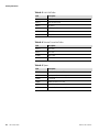
Ordering Information
Table A–3. Lids & Lid Cables
P/N
Description
886161
Lid, BJ Services
810111
Cable, BJ Services lid
885971
Lid, Jupiter
810112
Cable, Jupiter lid
885748
Lid, MS Conn
818100
Cable, MS Conn
Table A–4. Detector-Transmitter Cables
P/N
Description
810121
20-ft. cable
810122
30-ft. cable
817603
100-ft. cable
817604
150-ft. cable
Table A–5. Spares
A-2
SGD-O User Guide
P/N
Description
050268
Housing with detector, no lid
45373B
Plastic spacer (ion chamber support)
542630
O-ring for lid
54860Z
Rubber grommet (Elast-o-vier)
885745
Detector housing with support
885746
Insulation kit, with desiccant packs
Thermo Fisher Scientific
Appendix B
Specifications
Results may vary under different operating conditions.
Table B–1. Gauge specifications
Measurement range
Cement: 0–28 PPG
Slurry: 0.8–2.8 SGU
Proppant concentration: 0–30 lb./prop/added/gal.
Precision
±0.5 to ±0.1 lb./gal. at 8 lb./gal. or ±0.006 to ±0.012 kg/L at 1 kL;
dependent on pipe ID, source size, and time constant
Accuracy
±0.1 PPG
Pipe size
Low pressure pipe: 2–10 in. (2.5–25 cm)
High pressure pipe: Up to 20,000 psi/1,360.9 atm/1,379 bar
Power requirements
12–24 Vdc, 4 VA
Output
4–20 mA, RS485, RS232
Shock/Vibration
Detector withstands shock of 200 drops onto concrete from 2 m.
Drops consistent with 100 in 1 azimuth followed by 100 drops in
perpendicular azimuth.
Operating temperature
-58°F to +140°F (-50°C to +60°C)
Housing
Source head: Model 5190/5192
Detector: Stainless steel 316 or carbon steel
Table B–2. SGD-O transmitter specifications
Thermo Fisher Scientific
Input
Standard DC power: 12 Vdc (9–15 V), 15 W
Optional DC power: 24 Vdc (20–28 V), 12 W
Optional AC power: 110/220 Vac (100–240 V), 50/60 Hz, 25 VA
Output
3.8–20.5 mA DC (adjustable operating range). Configurable as
isolated, self-powered (standard) or isolated, loop-powered (user
supplies 24 Vdc loop power). Maximum load: 700 ohms.
Serial communications
RS232, 1 terminal block
Update rate
4 times per second
Connectors
Amphenol quarter turn bayonet style, Jupiter or military-style
cable available; quick disconnect oilfield rugged connectors
Operating temperature
-40°F to +140°F (-40°C to +60°C)
Display
4-line, backlit LCD
SGD-O User Guide
B-1
Specifications
B-2
SGD-O User Guide
Keypad
10 keys, external
Housing
Stainless steel 316
Mounting
Transmitter can be mounted 150 ft. (45.72 m) from the detector
Thermo Fisher Scientific
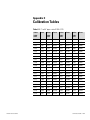
Appendix C
Calibration Tables
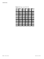
Table C–1. 2" to 5.5" pipes: ratios 0.200–0.279
Thermo Fisher Scientific
Ratios:
0.200–
0.219
Factor
Ratios:
0.220–
0.239
Factor
Ratios:
0.240–
0.259
Factor
Ratios:
0.260–
0.279
Factor
0.200
0.3308
0.220
0.3532
0.240
0.3750
0.260
0.3962
0.201
0.3320
0.221
0.3543
0.241
0.3761
0.261
0.3972
0.202
0.3331
0.222
0.3554
0.242
0.3771
0.262
0.3983
0.203
0.3342
0.223
0.3565
0.243
0.3782
0.263
0.3993
0.204
0.3354
0.224
0.3576
0.244
0.3793
0.264
0.4004
0.205
0.3365
0.225
0.3587
0.245
0.3803
0.265
0.4014
0.206
0.3376
0.226
0.3598
0.246
0.3814
0.266
0.4025
0.207
0.3387
0.227
0.3609
0.247
0.3825
0.267
0.4035
0.208
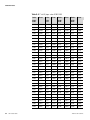
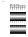
0.3399
0.228
0.3620
0.248
0.3835
0.268
0.4045
0.209
0.3410
0.229
0.3631
0.249
0.3846
0.269
0.4056
0.210
0.3421
0.230
0.3642
0.250
0.3857
0.270
0.4066
0.211
0.3432
0.231
0.3653
0.251
0.3867
0.271
0.4076
0.212
0.3443
0.232
0.3663
0.252
0.3878
0.272
0.4087
0.213
0.3455
0.233
0.3674
0.253
0.3888
0.273
0.4097
0.214
0.3466
0.234
0.3685
0.254
0.3899
0.274
0.4107
0.215
0.3477
0.235
0.3696
0.255
0.3909
0.275
0.4118
0.216
0.3488
0.236
0.3707
0.256
0.3920
0.276
0.4128
0.217
0.3499
0.237
0.3718
0.257
0.3930
0.277
0.4138
0.218
0.3510
0.238
0.3728
0.258
0.3941
0.278
0.4148
0.219
0.3521
0.239
0.3739
0.259
0.3951
0.279
0.4159
SGD-O User Guide
C-1
Calibration Tables
Table C–2. 2" to 5.5" pipes: ratios 0.280–0.399
C-2
SGD-O User Guide
Ratios:
0.280–
0.309
Factor
Ratios:
0.310–
0.339
Factor
Ratios:
0.340–
0.369
Factor
Ratios:
0.370–
0.399
Factor
0.280
0.4169
0.310
0.4471
0.340
0.4764
0.370
0.5049
0.281
0.4179
0.311
0.4481
0.341
0.4774
0.371
0.5059
0.282
0.4189
0.312
0.4491
0.342
0.4783
0.372
0.5068
0.283
0.4200
0.313
0.4501
0.343
0.4793
0.373
0.5077
0.284
0.4210
0.314
0.4511
0.344
0.4803
0.374
0.5087
0.285
0.4220
0.315
0.4520
0.345
0.4812
0.375
0.5096
0.286
0.4230
0.316
0.4530
0.346
0.4822
0.376
0.5105
0.287
0.4240
0.317
0.4540
0.347
0.4831
0.377
0.5115
0.288
0.4250
0.318
0.4550
0.348
0.4841
0.378
0.5124
0.289
0.4261
0.319
0.4560
0.349
0.4850
0.379
0.5133
0.290
0.4271
0.320
0.4570
0.350
0.4860
0.380
0.5143
0.291
0.4281
0.321
0.4579
0.351
0.4870
0.381
0.5152
0.292
0.4291
0.322
0.4589
0.352
0.4879
0.382
0.5161
0.293
0.4301
0.323
0.4599
0.353
0.4889
0.383
0.5170
0.294
0.4311
0.324
0.4609
0.354
0.4898
0.384
0.5180
0.295
0.4321
0.325
0.4619
0.355
0.4908
0.385
0.5189
0.296
0.4331
0.326
0.4628
0.356
0.4917
0.386
0.5198
0.297
0.4341
0.327
0.4638
0.357
0.4927
0.387
0.5208
0.298
0.4351
0.328
0.4648
0.358
0.4936
0.388
0.5217
0.299
0.4361
0.329
0.4658
0.359
0.4946
0.389
0.5226
0.300
0.4371
0.330
0.4667
0.360
0.4955
0.390
0.5235
0.301
0.4381
0.331
0.4677
0.361
0.4964
0.391
0.5244
0.302
0.4391
0.332
0.4687
0.362
0.4974
0.392
0.5254
0.303
0.4401
0.333
0.4696
0.363
0.4983
0.393
0.5263
0.304
0.4411
0.334
0.4706
0.364
0.4993
0.394
0.5272
0.305
0.4421
0.335
0.4716
0.365
0.5002
0.395
0.5281
0.306
0.4431
0.336
0.4726
0.366
0.5012
0.396
0.5290
0.307
0.4441
0.337
0.4735
0.367
0.5021
0.397
0.5300
0.308
0.4451
0.338
0.4745
0.368
0.5030
0.398
0.5309
0.309
0.4461
0.339
0.4754
0.369
0.5040
0.399
0.5318
Thermo Fisher Scientific
Calibration Tables
Table C–3. 2" to 5.5" pipes: ratios 0.400–0.519
Thermo Fisher Scientific
Ratios:
0.400–
0.429
Factor
Ratios:
0.430–
0.459
Factor
Ratios:
0.460–
0.489
Factor
Ratios:
0.490–
0.519
Factor
0.400
0.5327
0.430
0.5599
0.460
0.5864
0.490
0.6124
0.401
0.5336
0.431
0.5608
0.461
0.5873
0.491
0.6133
0.402
0.5345
0.432
0.5616
0.462
0.5882
0.492
0.6142
0.403
0.5355
0.433
0.5625
0.463
0.5890
0.493
0.6150
0.404
0.5364
0.434
0.5634
0.464
0.5899
0.494
0.6159
0.405
0.5373
0.435
0.5643
0.465
0.5908
0.495
0.6167
0.406
0.5382
0.436
0.5652
0.466
0.5917
0.496
0.6176
0.407
0.5391
0.437
0.5661
0.467
0.5925
0.497
0.6184
0.408
0.5400
0.438
0.5670
0.468
0.5934
0.498
0.6193
0.409
0.5409
0.439
0.5679
0.469
0.5943
0.499
0.6202
0.410
0.5418
0.440
0.5688
0.470
0.5952
0.500
0.6210
0.411
0.5427
0.441
0.5697
0.471
0.5960
0.501
0.6219
0.412
0.5436
0.442
0.5706
0.472
0.5969
0.502
0.6227
0.413
0.5446
0.443
0.5714
0.473
0.5978
0.503
0.6236
0.414
0.5455
0.444
0.5723
0.474
0.5986
0.504
0.6244
0.415
0.5464
0.445
0.5732
0.475
0.5995
0.505
0.6253
0.416
0.5473
0.446
0.5741
0.476
0.6004
0.506
0.6261
0.417
0.5482
0.447
0.5750
0.477
0.6012
0.507
0.6270
0.418
0.5491
0.448
0.5759
0.478
0.6021
0.508
0.6278
0.419
0.5500
0.449
0.5767
0.479
0.6030
0.509
0.6287
0.420
0.5509
0.450
0.5776
0.480
0.6038
0.510
0.6295
0.421
0.5518
0.451
0.5785
0.481
0.6047
0.511
0.6304
0.422
0.5527
0.452
0.5794
0.482
0.6056
0.512
0.6312
0.423
0.5536
0.453
0.5803
0.483
0.6064
0.513
0.6321
0.424
0.5545
0.454
0.5812
0.484
0.6073
0.514
0.6329
0.425
0.5554
0.455
0.5820
0.485
0.6081
0.515
0.6338
0.426
0.5563
0.456
0.5829
0.486
0.6090
0.516
0.6346
0.427
0.5572
0.457
0.5838
0.487
0.6099
0.517
0.6354
0.428
0.5581
0.458
0.5847
0.488
0.6107
0.518
0.6363
0.429
0.5590
0.459
0.5855
0.489
0.6116
0.519
0.6371
SGD-O User Guide
C-3
Calibration Tables
Table C–4. 2" to 5.5" pipes: ratios 0.520–0.639
C-4
SGD-O User Guide
Ratios:
0.520–
0.549
Factor
Ratios:
0.550–
0.579
Factor
Ratios:
0.580–
0.609
Factor
Ratios:
0.610–
0.639
Factor
0.520
0.6380
0.550
0.6631
0.580
0.6877
0.610
0.7120
0.521
0.6388
0.551
0.6639
0.581
0.6885
0.611
0.7128
0.522
0.6397
0.552
0.6647
0.582
0.6893
0.612
0.7136
0.523
0.6405
0.553
0.6655
0.583
0.6901
0.613
0.7144
0.524
0.6413
0.554
0.6664
0.584
0.6910
0.614
0.7152
0.525
0.6422
0.555
0.6672
0.585
0.6918
0.615
0.7160
0.526
0.6430
0.556
0.6680
0.586
0.6926
0.616
0.7168
0.527
0.6439
0.557
0.6688
0.587
0.6934
0.617
0.7176
0.528
0.6447
0.558
0.6697
0.588
0.6942
0.618
0.7184
0.529
0.6455
0.559
0.6705
0.589
0.6950
0.619
0.7192
0.530
0.6464
0.560
0.6713
0.590
0.6958
0.620
0.7200
0.531
0.6472
0.561
0.6721
0.591
0.6966
0.621
0.7208
0.532
0.6481
0.562
0.6730
0.592
0.6675
0.622
0.7216
0.533
0.6489
0.563
0.6738
0.593
0.6983
0.623
0.7224
0.534
0.6497
0.564
0.6746
0.594
0.6991
0.624
0.7232
0.535
0.6506
0.565
0.6754
0.595
0.6999
0.625
0.7239
0.536
0.6514
0.566
0.6763
0.596
0.7007
0.626
0.7247
0.537
0.6522
0.567
0.6771
0.597
0.7015
0.627
0.7255
0.538
0.6531
0.568
0.6779
0.598
0.7023
0.628
0.7263
0.539
0.6539
0.569
0.6787
0.599
0.7031
0.629
0.7271
0.540
0.6547
0.570
0.6795
0.600
0.7039
0.630
0.7279
0.541
0.6556
0.571
0.6804
0.601
0.7047
0.631
0.7287
0.542
0.6564
0.572
0.6812
0.602
0.7055
0.632
0.7295
0.543
0.6572
0.573
0.6820
0.603
0.7063
0.633
0.7303
0.544
0.6581
0.574
0.6828
0.604
0.7071
0.634
0.7311
0.545
0.6589
0.575
0.6836
0.605
0.7079
0.635
0.7319
0.546
0.6597
0.576
0.6844
0.606
0.7087
0.636
0.7327
0.547
0.6606
0.577
0.6853
0.607
0.7096
0.637
0.7335
0.548
0.6614
0.578
0.6861
0.608
0.7104
0.638
0.7343
0.549
0.6622
0.579
0.6869
0.609
0.7112
0.639
0.7351
Thermo Fisher Scientific
Calibration Tables
Table C–5. 2" to 5.5" pipes: ratios 0.640–0.759
Thermo Fisher Scientific
Ratios:
0.640–
0.669
Factor
Ratios:
0.670–
0.699
Factor
Ratios:
0.700–
0.729
Factor
Ratios:
0.730–
0.759
Factor
0.640
0.7358
0.670
0.7594
0.700
0.7826
0.730
0.8055
0.641
0.7366
0.671
0.7602
0.701
0.7834
0.731
0.8062
0.642
0.7374
0.672
0.7609
0.702
0.7841
0.732
0.8070
0.643
0.7382
0.673
0.7617
0.703
0.7849
0.733
0.8078
0.644
0.7390
0.674
0.7625
0.704
0.7857
0.734
0.8085
0.645
0.7398
0.675
0.7633
0.705
0.7864
0.735
0.8093
0.646
0.7406
0.676
0.7640
0.706
0.7872
0.736
0.8100
0.647
0.7414
0.677
0.7648
0.707
0.7880
0.737
0.8108
0.648
0.7422
0.678
0.7656
0.708
0.7887
0.738
0.8115
0.649
0.7429
0.679
0.7664
0.709
0.7895
0.739
0.8123
0.650
0.7437
0.680
0.7672
0.710
0.7903
0.740
0.8131
0.651
0.7445
0.681
0.7679
0.711
0.7910
0.741
0.8138
0.652
0.7453
0.682
0.7687
0.712
0.7918
0.742
0.8146
0.653
0.7461
0.683
0.7695
0.713
0.7926
0.743
0.8153
0.654
0.7469
0.684
0.7703
0.714
0.7933
0.744
0.8161
0.655
0.7477
0.685
0.7710
0.715
0.7941
0.745
0.8168
0.656
0.7484
0.686
0.7718
0.716
0.7948
0.746
0.8176
0.657
0.7492
0.687
0.7726
0.717
0.7956
0.747
0.8183
0.658
0.7500
0.688
0.7733
0.718
0.7964
0.748
0.8191
0.659
0.7508
0.689
0.7741
0.719
0.7971
0.749
0.8198
0.660
0.7516
0.690
0.7749
0.720
0.7979
0.750
0.8206
0.661
0.7524
0.691
0.7757
0.721
0.7987
0.751
0.8213
0.662
0.7531
0.692
0.7764
0.722
0.7994
0.752
0.8221
0.663
0.7539
0.693
0.7772
0.723
0.8002
0.753
0.8228
0.664
0.7547
0.694
0.7780
0.724
0.8009
0.754
0.8236
0.665
0.7555
0.695
0.7787
0.725
0.8017
0.755
0.8244
0.666
0.7563
0.696
0.7795
0.726
0.8025
0.756
0.8251
0.667
0.7570
0.697
0.7803
0.727
0.8032
0.757
0.8259
0.668
0.7578
0.698
0.7811
0.728
0.8040
0.758
0.8266
0.669
0.7586
0.699
0.7818
0.729
0.8047
0.759
0.8273
SGD-O User Guide
C-5
Calibration Tables
Table C–6. 2" to 5.5" pipes: ratios 0.760–0.799
C-6
SGD-O User Guide
Ratios:
0.760–
0.769
Factor
Ratios:
0.770–
0.779
Factor
Ratios:
0.780–
0.789
Factor
Ratios:
0.790–
0.799
Factor
0.760
0.8281
0.770
0.8356
0.780
0.8430
0.790
0.8504
0.761
0.8288
0.771
0.8363
0.781
0.8438
0.791
0.8512
0.762
0.8296
0.772
0.8371
0.782
0.8445
0.792
0.8519
0.763
0.8303
0.773
0.8378
0.783
0.8452
0.793
0.8526
0.764
0.8311
0.774
0.8386
0.784
0.8460
0.794
0.8534
0.765
0.8318
0.775
0.8393
0.785
0.8467
0.795
0.8541
0.766
0.8326
0.776
0.8400
0.786
0.8475
0.796
0.8549
0.767
0.8333
0.777
0.8408
0.787
0.8482
0.797
0.8556
0.768
0.8341
0.778
0.8415
0.788
0.8489
0.798
0.8563
0.769
0.8348
0.779
0.8423
0.789
0.8497
0.799
0.8571
Thermo Fisher Scientific
Calibration Tables
Table C–7. 6" pipes
Thermo Fisher Scientific
Ratios:
0.300–
0.329
Factor
Ratios:
0.330–
0.359
Factor
Ratios:
0.360–
0.389
Factor
Ratios:
0.390–
0.419
Factor
0.300
0.4416
0.330
0.4711
0.360
0.4998
0.390
0.5277
0.301
0.4426
0.331
0.4721
0.361
0.5007
0.391
0.5286
0.302
0.4436
0.332
0.4731
0.362
0.5017
0.392
0.5295
0.303
0.4446
0.333
0.4740
0.363
0.5026
0.393
0.5305
0.304
0.4456
0.334
0.4750
0.364
0.5036
0.394
0.5314
0.305
0.4466
0.335
0.4760
0.365
0.5045
0.395
0.5323
0.306
0.4476
0.336
0.4769
0.366
0.5054
0.396
0.5332
0.307
0.4486
0.337
0.4779
0.367
0.5064
0.397
0.5341
0.308
0.4496
0.338
0.4789
0.368
0.5073
0.398
0.5350
0.309
0.4506
0.339
0.4798
0.369
0.5082
0.399
0.5359
0.310
0.4516
0.340
0.4808
0.370
0.5092
0.400
0.5369
0.311
0.4525
0.341
0.4817
0.371
0.5101
0.401
0.5378
0.312
0.4535
0.342
0.4827
0.372
0.5110
0.402
0.5387
0.313
0.4545
0.343
0.4837
0.373
0.5120
0.403
0.5396
0.314
0.4555
0.344
0.4846
0.374
0.5129
0.404
0.5405
0.315
0.4565
0.345
0.4856
0.375
0.5138
0.405
0.5414
0.316
0.4575
0.346
0.4865
0.376
0.5148
0.406
0.5423
0.317
0.4585
0.347
0.4875
0.377
0.5157
0.407
0.5432
0.318
0.4594
0.348
0.4884
0.378
0.5166
0.408
0.5441
0.319
0.4604
0.349
0.4894
0.379
0.5176
0.409
0.5450
0.320
0.4614
0.350
0.4903
0.380
0.5185
0.410
0.5459
0.321
0.4624
0.351
0.4913
0.381
0.5194
0.411
0.5468
0.322
0.4633
0.352
0.4922
0.382
0.5203
0.412
0.5477
0.323
0.4643
0.353
0.4932
0.383
0.5213
0.413
0.5486
0.324
0.4653
0.354
0.4941
0.384
0.5222
0.414
0.5495
0.325
0.4663
0.355
0.4951
0.385
0.5231
0.415
0.5504
0.326
0.4672
0.356
0.4960
0.386
0.5240
0.416
0.5513
0.327
0.4682
0.357
0.4970
0.387
0.5249
0.417
0.5522
0.328
0.4692
0.358
0.4979
0.388
0.5259
0.418
0.5531
0.329
0.4702
0.359
0.4989
0.389
0.5268
0.419
0.5540
SGD-O User Guide
C-7
Calibration Tables
Table C–8. 8" pipes
C-8
SGD-O User Guide
Ratios:
0.200–
0.229
Factor
Ratios:
0.230–
0.259
Factor
Ratios:
0.260–
0.289
Factor
Ratios:
0.290–
0.319
Factor
0.200
0.3418
0.230
0.3752
0.260
0.4071
0.290
0.4379
0.201
0.3429
0.231
0.3763
0.261
0.4082
0.291
0.4389
0.202
0.3440
0.232
0.3773
0.262
0.4092
0.292
0.4399
0.203
0.3452
0.233
0.3784
0.263
0.4103
0.293
0.4409
0.204
0.3463
0.234
0.3795
0.264
0.4113
0.294
0.4419
0.205
0.3474
0.235
0.3806
0.265
0.4123
0.295
0.4429
0.206
0.3486
0.236
0.3817
0.266
0.4134
0.296
0.4439
0.207
0.3497
0.237
0.3827
0.267
0.4144
0.297
0.4449
0.208
0.3508
0.238
0.3838
0.268
0.4155
0.298
0.4459
0.209
0.3520
0.239
0.3849
0.269
0.4165
0.299
0.4469
0.210
0.3531
0.240
0.3860
0.270
0.4175
0.300
0.4479
0.211
0.3542
0.241
0.3870
0.271
0.4186
0.301
0.4489
0.212
0.3553
0.242
0.3881
0.272
0.4196
0.302
0.4499
0.213
0.3564
0.243
0.3892
0.273
0.4206
0.303
0.4509
0.214
0.3575
0.244
0.3903
0.274
0.4216
0.304
0.4519
0.215
0.3587
0.245
0.3913
0.275
0.4227
0.305
0.4529
0.216
0.3598
0.246
0.3924
0.276
0.4237
0.306
0.4539
0.217
0.3609
0.247
0.3934
0.277
0.4247
0.307
0.4549
0.218
0.3620
0.248
0.3945
0.278
0.4257
0.308
0.4559
0.219
0.3631
0.249
0.3956
0.279
0.4268
0.309
0.4568
0.220
0.3642
0.250
0.3966
0.280
0.4278
0.310
0.4578
0.221
0.3653
0.251
0.3977
0.281
0.4288
0.311
0.4588
0.222
0.3664
0.252
0.3987
0.282
0.4298
0.312
0.4598
0.223
0.3675
0.253
0.3998
0.283
0.4308
0.313
0.4608
0.224
0.3686
0.254
0.4008
0.284
0.4318
0.314
0.4618
0.225
0.3697
0.255
0.4019
0.285
0.4329
0.315
0.4627
0.226
0.3708
0.256
0.4030
0.286
0.4339
0.316
0.4637
0.227
0.3719
0.257
0.4040
0.287
0.4349
0.317
0.4647
0.228
0.3730
0.258
0.4050
0.288
0.4359
0.318
0.4657
0.229
0.3741
0.259
0.4061
0.289
0.4369
0.319
0.4667
Thermo Fisher Scientific
Calibration Tables
Table C–9. 10" pipes: ratios 0.100–0.219
Thermo Fisher Scientific
Ratios:
0.100–
0.129
Factor
Ratios:
0.130–
0.159
Factor
Ratios:
0.160–
0.189
Factor
Ratios:
0.190–
0.219
Factor
0.100
0.2154
0.130
0.2565
0.160
0.2946
0.190
0.3304
0.101
0.2168
0.131
0.2578
0.161
0.2958
0.191
0.3315
0.102
0.2182
0.132
0.2591
0.162
0.2971
0.192
0.3327
0.103
0.2196
0.133
0.2605
0.163
0.2983
0.193
0.3338
0.104
0.2211
0.134
0.2618
0.164
0.2995
0.194
0.3350
0.105
0.2225
0.135
0.2631
0.165
0.3007
0.195
0.3361
0.106
0.2239
0.136
0.2644
0.166
0.3019
0.196
0.3373
0.107
0.2253
0.137
0.2656
0.167
0.3031
0.197
0.3384
0.108
0.2267
0.138
0.2669
0.168
0.3043
0.198
0.3396
0.109
0.2281
0.139
0.2682
0.169
0.3055
0.199
0.3407
0.110
0.2295
0.140
0.2695
0.170
0.3058
0.200
0.3419
0.111
0.2309
0.141
0.2708
0.171
0.3080
0.201
0.3430
0.112
0.2323
0.142
0.2721
0.172
0.3092
0.202
0.3441
0.113
0.2336
0.143
0.2733
0.173
0.3104
0.203
0.3453
0.114
0.2350
0.144
0.2746
0.174
0.3115
0.204
0.3464
0.115
0.2364
0.145
0.2759
0.175
0.3127
0.205
0.3475
0.116
0.2378
0.146
0.2772
0.176
0.3139
0.206
0.3487
0.117
0.2391
0.147
0.2784
0.177
0.3151
0.207
0.3498
0.118
0.2405
0.148
0.2797
0.178
0.3163
0.208
0.3509
0.119
0.2418
0.149
0.2809
0.179
0.3175
0.209
0.3520
0.120
0.2432
0.150
0.2822
0.180
0.3187
0.210
0.3532
0.121
0.2445
0.151
0.2835
0.181
0.3198
0.211
0.3543
0.122
0.2459
0.152
0.2847
0.182
0.3210
0.212
0.3554
0.123
0.2472
0.153
0.2859
0.183
0.3222
0.213
0.3565
0.124
0.2486
0.154
0.2872
0.184
0.3234
0.214
0.3576
0.125
0.2499
0.155
0.2884
0.185
0.3245
0.215
0.3587
0.126
0.2512
0.156
0.2897
0.186
0.3257
0.216
0.3598
0.127
0.2526
0.157
0.2909
0.187
0.3269
0.217
0.3610
0.128
0.2539
0.158
0.2921
0.188
0.3280
0.218
0.3621
0.129
0.2552
0.159
0.2934
0.189
0.3292
0.219
0.3632
SGD-O User Guide
C-9
Calibration Tables
Table C–10. 10" pipes: ratios 0.220–0.249
C-10
SGD-O User Guide
Ratios:
0.220–
0.229
Factor
Ratios:
0.230–
0.239
Factor
Ratios:
0.240–
0.249
Factor
0.220
0.3643
0.230
0.3752
0.240
0.3860
0.221
0.3654
0.231
0.3763
0.241
0.3871
0.222
0.3665
0.232
0.3774
0.242
0.3882
0.223
0.3676
0.233
0.3785
0.243
0.3892
0.224
0.3687
0.234
0.3796
0.244
0.3903
0.225
0.3698
0.235
0.3807
0.245
0.3914
0.226
0.3709
0.236
0.3817
0.246
0.3924
0.227
0.3720
0.237
0.3828
0.247
0.3935
0.228
0.3731
0.238
0.3839
0.248
0.3946
0.229
0.3741
0.239
0.3850
0.249
0.3956
Thermo Fisher Scientific
Appendix D
Gauge Calibration Records
Following is a condensed version of the procedure detailed in Chapter 4. It
is assumed that the gauge has been installed properly, the shutter is open (if
applicable), and the pipe is empty of any fluid.
Date
Gauge
Pipe Size (inches)
Pipe ID (inches)
Location or DAC
Step
Description
Command DAC
1
Erase memory.
74
2
Load standard oilfield setup.
1016
3
Enter pipe ID (inches).
4
Standardize the gauge on air. When complete, fill pipe with
clean water. Allow detector to stabilize for five minutes.
121
5
Calibrate on water.
4
6
Record the water/air ratio.
118003
7
Use pipe size and water/air ratio to obtain the factor from the
tables (Appendix C). Record the factor.
Calibration tables
(in user guide)
8
Clear “Cal Point Pending” message.
9
Reset CAL/REF ratio to 1.00.
10
Standardize the gauge on water.
11
Record the water signal value.
12
Calculate the ZnCl signal value: ZnCl = Water signal * Factor.
13
Enter the calculated ZnCl signal value.
14
Hold the output at ZnCl signal value.
15
Displayed density should be near 1.812 g/ml. (Record value.)
16
Record the slope correction factor.
049003
17
Record the carrier specific gravity.
085003
18
Displayed density should be 1.812 g/ml. Adjust slope
correction factor if necessary until density is 1.812 g/ml.
049003
19
Clear all holds.
20
Displayed density should be 1.000 g/ml. (Record value.)
Value
048003
49
086003
121
128003
133003
137
9
Completed by:
Thermo Fisher Scientific
SGD-O User Guide
D-1
This page intentionally left blank.
Appendix E
Commonly Used Parameter &
Command DACs
The following tables provide regularly used parameter and command
DACs.
Table E–1. Common parameter DACs
Thermo Fisher Scientific
Parameter Description
DAC
Notes
Snapshot of detector signal
112003
0 to 65540 corresponds to 0 to10 V input
Standardization value
128003
0 to 65540
Standardization value corrected for
source decay
121003
Snapshot of channel 1
116013
Snapshot of channel 2
116023
Time constant
007004
128 seconds (8 seconds recommended)
Slope correction factor (labeled
“slope”)
049003
1.000
Calibration density
024003
Top of span (reading at 20 mA)
(Solids added / Volume of carrier)
114013
2500 g/L (metric)
30 lb/gal (English)
Bottom of span (reading at 4 mA)
115013
0.00
Pipe internal diameter
048003
inches
Cal/Ref ratio
086003
1.0
Solids density
083003
2.65 g/cm3
Carrier density
085003
0.9982 g/cm3
Carrier attenuation coefficient
019003
0.086 cm2/g
Solids attenuation coefficient
020003
0.077 cm2/g
Weeks since last reference
054003
Enable less than 0 and greater than
100%
043030
Enable phantom measurements (HV
control)
045020
SGD-O User Guide
E-1
Commonly Used Parameter & Command DACs
Parameter Description
DAC
Enable protected memory
(DensityPRO)
013010
Enable protected memory
(LevelPRO)
005010
High voltage hold value
070003
Notes
Table E–2. Common command DACs
E-2
SGD-O User Guide
Command Description
DAC
Preload configuration for SGD-O oilfield in metric units
1014
Preload configuration for SGD-O oilfield in English units
1016
Hold input at value indicated by parameter 133003
137
Hold current output at 50% (12 mA for a 4–20 mA)
2
Hold current output at maximum (20 mA for 4–20 mA)
5
Hold current output at minimum (4 mA for 4–20 mA)
8
Clear all holds
9
Toggle status message
72
Reset without clearing data
81
Calibration command
80
Erase all entries except comm setup
82
Erase all entries
74
Clear protected data
159
Standardization command
103
Use latest calibration value
49
Thermo Fisher Scientific
Appendix F
Toxic & Hazardous Substances
Tables
The English and Chinese versions of the Toxic and Hazardous Substances
tables are below.
Thermo Fisher Scientific
SGD-O User Guide
F-1
This page intentionally left blank.
Appendix G
Related Technical Bulletins
This appendix provides a list of technical bulletins related to this product as
of the release date of this document revision. For the most current
bulletins, please go to thermoscientific.com. Enter the product name
(SGD-O) as the search term and click the Resources tab.
Table G–1. Technical bulletins
Thermo Fisher Scientific
TB #
Title
TB-0416-002
Adjusting Gain Settings for the Thermo Scientific SGD-O FSU Pre-Amp
Board
TB-0416-005
Troubleshooting the Thermo Scientific SGD-O FSU Pre-Amp Board
TB-0416-017
Using the Thermo Scientific SGD-O Power Cable for Multiple
Applications
TB-0416-018
Transmitter Models Used with the Thermo Scientific SGD-O Density
Gauge
SGD-O User Guide
G-1
This page intentionally left blank.
Thermo Fisher Scientific
81 Wyman Street
P.O. Box 9046
Waltham, Massachusetts 02454-9046
United States
www.thermofisher.com