1
User's Manual: Series 350T
Model 350T Millivolt/Thermocouple DC Powered Transmitters
______________________________________________________________________________
Table of Contents
Page
Introduction ...................................................................................................................2
Description ....................................................................................................................3
Specifications ................................................................................................................3
Installation.....................................................................................................................7
Calibration.....................................................................................................................9
General Maintenance ....................................................................................................13
List of Drawings
Electrical Connections: MV/TC Input (No. 4501-249) ................................................14
Calibration Connections: MV/TC Input (No. 4501-250)..............................................15
Configuration Jumper Location: MV/TC Input (No. 4501-251 ...................................16
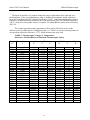
Dimensions: DIN Rail Mounting (No. 4501-252) ........................................................17
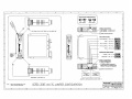
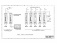
Electrical Connections: Power Supply Configurations (No. 4501-254).......................18
==================================
IMPORTANT SAFETY CONSIDERATIONS
==================================
It is very important for the user to consider the possible adverse effects of power, wiring,
component, sensor, or software failures in designing any type of control or monitoring system.
This is especially important where economic property loss or human life is involved. It is
important that the user employ satisfactory overall system design. It is agreed between the Buyer
and Acromag, that this is the Buyer's responsibility.
Acromag, Inc.
30765 S. Wixom Road, P.O. Box 437
Wixom, Michigan 48393-7037, USA
Tel: (248) 624-1541
Fax: (248) 624-9234
Copyright 1993 Acromag, Inc. Printed in USA
Data and specifications subject to change without notice
8500-327-B93J012
Series 350T User’s Manual
Millivolt/Thermocouple
INSTRUCTIONS: SERIES 350T
Millivolt/Thermocouple DC Powered Transmitters
INTRODUCTION:
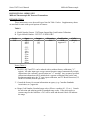
These instructions cover the model types listed in Table 1 below. Supplementary sheets
are attached for units with special options or features.
Table 1:
A. Model Number Format: 350T-Input-Output-Mtg-Certification-Calibration
B. Typical Model Number: 350T-TC1-Y-DIN-NCR-C
Series
350T
-Input
-MV1
-MV2
-MV3
-Output
-Y
-V0
-V5
-Mounting
-DIN
-Certification
-NCR
Approval**
-Calib. *
(Blank)
-C
-TC1
-TC3
-Jlxx
-Klxx
-Tlxx
-Elxx
-Rlxx
-Slxx
-BLxx
Notes (Table 1):
* The MV1, MV2 and TC1 can be ordered with or without factory calibration ("-C"
option). All other input types except custom linearizer ranges automatically include
calibration to the customer's specification (no "-C" needed). Any customer specified
calibration information will be included on a separate calibration label on the unit.
For thermocouple units, the TC type, input calibration, and TC Break Detection (UP,
DOWN or NONE) must be specified.
** Consult the factory for current information on agency (e.g. Canadian Standards
Association, etc.) approvals.
xx Range Code Number: Standard range code will have a number (01, 12, etc.). Consult
the selection and ordering guide for standard range codes. If the unit requires a
custom range for the linearizer a "00" will be used and the unit's label will indicate
the range.
-2-
Series 350T User’s Manual
Millivolt/Thermocouple
DESCRIPTION:
These DC powered transmitters condition millivolt or thermocouple input signals and
convert the signal to a process current or voltage output. Input circuit isolation is standard. The
unit also provides high input impedance, thermocouple reference junction compensation, upscale
or downscale thermocouple break detection, and wide-range zero and span adjustments.
Optionally, a five segment linearizer is available to correct for thermocouple non-linearity over a
customer-specified calibration range. The transmitters are RFI and EMI protected, operate over
large temperature ranges, and feature excellent temperature coefficients, which minimize effects
from the harsh plant environment.
The 350T Series are DIN-rail mounted transmitters designed to be used as functional
components that provide the user with a modular approach to the varied applications in the field.
The Series 350T complements the Acromag Series 250T two-wire transmitter line, providing the
same input conditioning for three-wire applications. That is, Series 350T transmitters require a
separate power supply connection, while the output signal and DC power share a common lead.
The small package size, low power requirements, and wide supply range offers maximum
flexibility to the system designer. As a three-wired DC powered device, it can also be used in
critical applications that require the use of redundant supplies. The Series 350T includes reverse
polarity protection, current limiting, and operates from a single 10V to 36V DC supply. In
applications requiring only a single transmitter, the 350T can use available DC power, or it can
be wired to an optional Series 35PS power supply module. The Series 35PS power supply
module receives it's power from either 115V AC or 230V AC. Applications requiring multiple
transmitters at a single location can more efficiently share a single DC supply. The modular
approach of this design and companion Acromag flat-pack modules allows additional
transmitters, input modules, isolators, and alarms to be easily integrated, as required. See
Drawing 4501-249 for a simplified Series 350T schematic.
Input wiring is inserted in the bottom of the unit, while output and power wiring is
inserted at the top of the unit. Screws to secure the wiring are located on the front panel.
Connectors are screw-clamp type and accept wire size up to 14 AWG.
SPECIFICATIONS:
Function: This family of isolated, DC Voltage powered, transmitters condition
either a millivolt or thermocouple signal, have input circuit isolation
and convert the input signal to a process current or voltage output.
The output and DC power share a common terminal (3-Wire connection).
Wide-range zero and span adjustments utilize 22-turn potentiometers
which are accessible from the front of the unit. Transmitter is
DIN-rail mounted.
MODEL/SERIES: 350T- (Color coded with a white label)
-3-
Series 350T User’s Manual
Millivolt/Thermocouple
INPUT: Millivolt and Thermocouple. Input span and zero ranges are adjustable as specified
below, except for linearized thermocouples and special ranges which are factory
calibrated per customer specifications. Both the span and zero adjustment capability are
covered in two ranges, and are configured by internal jumpers on the circuit board. The
narrow span units (-MV3 & -TC3) are configured and calibrated per customer
requirements.
-MV1: Millivolt - Standard Span: Span: 5 to 55mV; Zero: -5 to +25mV.
-MV2: Millivolt - Wide Span: Span: 25 to 250mV; Zero: -25 to +125mV.
-MV3: Millivolt - Narrow Span (Custom Calibration): Unit handles
millivolt spans from 3 to 5mV with the range factory calibrated
to customer specifications.
-TC1: Thermocouple - Standard Span: TC Types J, K, T, E, R, S
and B (Non-linearized): The TC Type is field selected via an
Internal jumper.
J: ISA Type J, Iron/Constantan:
Span: 100 to 760oC Zero: -100 to 450oC
K: ISA Type K, Chromel/Alumel:
Span: 100 to 1200oC Zero: -100 to 600oC
T: ISA Type T, Copper/Constantan:
Span: 100 to 400oC Zero: -150 to +300 oC
E: ISA Type E, Chromel/Constantan:
Span: 100 to 700oC Zero: -100 to +350 oC
R: ISA Type R, Plat/Plat 13% Rhod:
Span: 550 to 1750oC Zero: 0 to 1200oC.
S: ISA Type S, Plat/Plat 10% Rhod:
Span: 550 to 1750oC Zero: 0 to 1200oC.
B: ISA Type B, Plat 6% Rhod/Plat 30% Rhod:
Span: 1000 to 1820oC Zero: 0 to 1000oC.
-TC3: Thermocouple - Narrow Span (Custom Calibration): Unit handles temperature
equivalent millivolt spans from 3 to 5mV with the range factory calibrated to
customer specifications. NOTE: The Thermocouple type and TC-Break (UP,
DOWN or NONE) must also be specified. The linearization option is not
available (or needed).
The following group of input types include the linearization circuit. The standard span
transmitter is linearized per the customer specified calibration range. The range code (xx
in Input field below) is used to represent the input range required. Consult the Selection
and Ordering Guide for standard range codes. Custom range codes are also available
--consult the factory.
-JLxx: ISA Type J, linearized.
-KLxx: ISA Type K, linearized.
-TLxx: ISA Type T, linearized.
-ELxx: ISA Type E, linearized.
-RLxx: ISA Type R, linearized.
-SLxx: ISA Type S, linearized.
-BLxx: ISA Type B, linearized.
-4-
Series 350T User’s Manual
Millivolt/Thermocouple
Isolation: The input circuit is electrically isolated from the output and power circuits, allowing
the input to operate at up to 250V AC, or 354V DC off ground, on a continuous basis (will
withstand 1500V AC dielectric strength test for one minute without breakdown). This
complies with test requirements outlined in ANSI/ISA-S82.01-1988 for the voltage rating
specified.
OUTPUT: Process Current or Voltage output. The output shares a common with
the power supply. Voltage outputs are designed to provide true voltage
output, with zero volts included, and to be stable with capacitive
loads.
-Y : 4 to 20mA DC (see Load Resistance Range Equation below)
-V0: 0 to 10V DC into 10,000 ohms or greater
-V5: 0 to 5V DC into 5,000 ohms or greater
Load Resistance Range Equation (-Y output option): The maximum load
resistance for 20mA compliance is a function of input supply voltage as
follows:
R-Load (Maximum) = (Minimum VDC supply - 2.5V) / 0.02A
At 10.0V DC supply, R-Load = 0 to 375 ohms
At 12.5V DC supply, R-Load = 0 to 500 ohms
At 15.0V DC supply, R-Load = 0 to 625 ohms
At 24.0V DC supply, R-Load = 0 to 1075 ohms
Output Limiting: Voltage units: 150% of full scale output, nominal; Current
units; 125% of full-scale output, nominal.
Output Ripple: Less than +/-0.1% of the maximum output span.
Power: An external DC power supply is required between the output (P) and (-) terminals.
Transmitter current is for rated supply inputs, full-scale output, and no-load on voltage
output units. Diode on transmitter provides reverse polarity protection. CAUTION: Do
not exceed 36V DC peak, to avoid damage to the transmitter.
A. Process Current Output (-Y): +10.0V to 36.0V DC, 30mA (35mA at
current limit).
B. Voltage Output (-V0): +12.5V to 36.0V DC, 9mA maximum.
C. Voltage Output (-V5): +10.0V to 36.0V DC, 9mA maximum.
Power Supply Effect:
DC Volts: less than +/-0.001% of output span per volt DC, for rated
power supply variations (+/-0.003% per volt for narrow span units).
60/120 Hz ripple: less than +/-0.01% of span per volt peak-to-peak of
power supply ripple.
-5-
Series 350T User’s Manual
Millivolt/Thermocouple
Input Impedance:
A. Millivolt and Thermocouple Inputs (Without TC Break Detection): 1.0M
ohm at 10mV span, typical; input current, +/-10nA, typical.
B. Thermocouple Inputs (Utilizing TC Break Detection): 400K ohm at
10mV span; input current, +/-25nA, typical (+/-30nA, maximum).
Thermocouple Models:
A. Thermocouple Reference Junction Compensation: standard on all
thermocouple units and functional over the entire operating
temperature range. Includes unique circuitry to correct for
reference junction non-linearity over ambient temperature.
Reference Junction Compensation Ambient Temperature Effect:
+/- 0.02oC/oC, typical.
B. Thermocouple Break Detection: user-selectable for Upscale,
Downscale, or None. Up or downscale break detection is
selectable via an internal jumper and activated via an external
jumper.
Reference Test Conditions: Input: 0-10mV with a 100 ohm resistive source; Output (-Y units):
4-20mA DC (500 Ohm load); Output (-Vx units): 0-10V DC into 10K ohms or greater;
Ambient 77oF (25oC); +15V DC supply.
Accuracy: Better than +/-0.1% of calibrated span or +/-0.01 mV, whichever is greater. This
error includes the combined effects of transmitter repeatability, hysteresis, terminal point
linearity (conformity instead of linearity for thermocouple inputs, non-linearized), and
adjustment resolution. Does not include sensor error.
Linearization (-xLxx) Option: Optional linearized thermocouple units contain a five segment
linearizer to correct for thermocouple non-linearity. This option offers low cost
linearization and provides a minimum 10 to 1 improvement +/-0.1% in the linearity curve
for the specified range of type J, K, T, R, S, E, and B ISA rated thermocouples.
Ambient Temperature Range: -13oF to 185oF (-25oC to 85oC).
Ambient Temperature Effect: Less than +/-0.01% of output span per oF
(+/-0.018% per oC) over the ambient temperature range for reference test conditions; +/0.025% of output span per oF (+/-0.045% per oC) for narrow span units at 5mV span.
Specification includes the combined effects of zero and span over temperature.
Bandwidth: -3dB at 3 Hz, typical.
Response Time: For a step input, the output reaches 98% of output span in
300ms, typical.
Noise Rejection:
Common Mode: 130dB at 60 Hz, 100 ohm unbalance, typical.
Normal Mode: 30dB at 60 Hz, 100 ohm source, typical.
-6-
Series 350T User’s Manual
Millivolt/Thermocouple
RFI Resistance: Less than +/-0.5% of output span with RFI field strengths of
up to 10V/meter at frequencies of 27, 151 and 467 MHz.
EMI Resistance:
Less than +/-0.25% of output span effect with switching
solenoids or commutator motors.
Surge Withstand Capability (SWC):
Input/Output terminations rated per
ANSI/IEEE C37.90-1978. Unit is tested to a standardized test waveform
that is representative of surges (high frequency transient electrical
interference), observed in actual installations.
Construction:
Printed Circuit Boards: Military grade FR-4 epoxy glass circuit board.
Terminals: Compression type, wire size 14 AWG maximum.
Case: Self-extinguishing NYLON Type 6.6 polyamide thermoplastic UL94 V-2,
color black. General Purpose, NEMA Type 1 enclosure.
Printed Circuit Board Coating: Fungus resistant acrylic conformal coat.
Mounting Position: Position insensitive.
MOUNTING:
-DIN: General Purpose Housing, DIN-Rail Mount - "G" & "T" rails. "G"
Rail (32mm), Type EN50035; "T" Rail (35mm), Type EN50022. Refer to
Drawing 4501-252 for outline and clearance dimensions.
Shipping Weight: 1 pound (0.45Kg) packed.
CERTIFICATION: Consult the factory for current information on the availability of agency
(e.g. Canadian Standards Association, Factory Mutual, etc.) approvals.
-NCR: No Certification Required.
INSTALLATION:
The transmitter is packaged in a general purpose type of enclosure. Use an auxiliary
enclosure to protect against unfavorable environments and locations. Maximum operating
ambient temperatures should be within -13 to 185oF (-25 to 85oC) for satisfactory performance.
If the unit is factory calibrated, it is ready for installation. Connect as shown in the connection
diagram of Drawing 4501-249. If the unit is not factory calibrated, refer to the
"CALIBRATION" section.
Mounting: Mount transmitter assembly - refer to Drawing 4501-252 for mounting
and clearance dimensions.
DIN Rail Mounting: Using suitable fastening hardware, secure the
DIN rail to the designated mounting surface. A transmitter, can be
mounted to either the "T" or "G" Rail. Installation of the
transmitter to the rail depends on the type of DIN rail used. Units
can be mounted side by side on 1.0 inch centers, if required.
-7-
Series 350T User’s Manual
Millivolt/Thermocouple
"T" Rail (35mm), Type EN50022: To attach a transmitter to this
style of DIN rail, angle the top of the unit towards the rail and
locate the top groove of the adapter over the upper lip of the rail.
Firmly push the unit towards the rail until it snaps solidly into
place. To remove a transmitter, insert a screwdriver into the lower
arm of the connector and pull downwards while applying outward
pressure to the bottom of the unit.
"G" Rail (32mm), Type EN50035: To attach a transmitter to this
style of DIN rail, angle the unit so that the upper groove of the
adapter hooks under the top lip of the rail. Firmly push the unit
towards the rail until it snaps solidly into place. To remove a
transmitter, pull the lower part of the unit outwards until it
releases from the rail, lift unit from rail.
Electrical Connections:
Regardless of the mounting configuration employed, the electrical connections are
basically identical. The wire size used to connect the unit to the control system is not
critical. All terminal strips can accommodate wire from 14-26 AWG. Strip back the
insulation 1/4-inch on each lead before installing it into the terminal block. Input wiring
may be either shielded or unshielded twisted pair. Output wires should be twisted pair.
Since common mode voltages can exist on signal wiring, adequate wire insulation should
be used and proper wiring practices followed. It is recommended that the output and
power wiring be separated from the signal wiring for safety as well as for low noise
pickup.
1. Power: Connect DC power supply per connection diagram, refer to Drawing 4501-249.
These transmitters operate from DC power supplies only. Power supply voltage is not critical
and normally should be from 10.0V to 36V DC. The supply voltage must not exceed 36
Volts, even instantaneously, and must be adequate to furnish full-scale current or voltage to
the load. Variations in power supply voltage, above the minimum required, or load
resistance have negligible effect on transmitter accuracy. Refer to "POWER" in the
preceding SPECFICATIONS section for current requirements. The minus (-) power supply
lead and the minus (-) output lead share a common terminal. This device includes input
current limiting and reverse polarity protection. Refer to Drawing 4501-254 for other power
supply configurations.
Ripple and Noise: Power supply ripple at 60Hz/120Hz is reduced at the load by the
transmitter. The ripple at the load will be less than +/-0.01% of span per volt peak-to-peak of
power supply ripple.
-8-
Series 350T User’s Manual
Millivolt/Thermocouple
2. Output: Connect output per connection diagram, refer to Drawing
4501-249. Load range is a function of the module's output type;
refer to "Output" in the preceding "SPECIFICATIONS" section. The
output shares a common with the power supply.
3. Grounding: The transmitter housing is plastic and does not require an earth ground
connection.
4. Input: Connect input per connection diagram, observe proper polarity, see label for input
type. If unit is factory calibrated, the calibration label indicates range of input. NOTE: The
input circuit is electrically isolated from the output/power circuit allowing the input to
operate up to 250V AC or 354V DC off ground on a continuous basis. If your input is a
thermocouple, the thermocouple break circuit will be activated by placing a short jumper
wire between the input "+" and "L" terminals of the transmitter. The type of Break
Detection, UP or DOWN, is configured internal to the transmitter - see CALIBRATION
Section.
CALIBRATION:
A. TRANSMITTER:
This section provides information for configuration and calibration. If the unit was
factory calibrated, jumpers have been placed in their proper positions and verification of the
calibration can be made per the Adjustment Procedure. If the calibration of the unit is to be
changed, first go to the "Shunt Block Configuration Procedure" before going to the Transmitter
Adjustment Procedure."
1.
Transmitter - Shunt Block Configuration Procedure:
The Thermocouple transmitter is quite universal in that it can be configured for any of the
standard Thermocouple types. The Zero and Span adjustment range and the Thermocouple
Break, UP or DOWN, can be configured. Before the adjustment procedure can proceed, the
jumpers have to be configured to the requirements of the application (refer to Drawing 4501-251
for details). To gain access to the Configuration Jumpers, first remove transmitter from the
installation. Second, remove the circuit boards from the plastic enclosure as described in the
Disassembly Procedure below. Third, configure jumpers (shunt blocks) as described in the
Jumper Configuration procedure below. NOTE: calibration per the Adjustment Procedure should
be performed before the circuit boards `re reassembled within the plastic enclosure.
-9-
Series 350T User’s Manual
Millivolt/Thermocouple
Disassembly Procedure for the 350T Plastic Housing:
The plastic housing has no screws, it "snaps" together. A flat-head screwdriver (Acromag
5021-216 or equivalent) is needed to pry the housing apart as described in the following steps.
CAUTION: Do not push the screwdriver blade into the housing more than approximately 0.1
inches while prying it apart. Handling of the printed circuit boards should only be done at a
static-free workstation, otherwise, damage to the electronics could result.
1. To begin disassembly (refer to Drawing 4501-251) place the screwdriver at point A (left side
of the transmitter). While pressing the blade into the seam, use a twisting motion to separate
the sides slightly. Repeat this operation at point B.
2. Now that the two pieces have been partially separated, use the screwdriver blade to work the
left side of the package loose by working around the transmitter and carefully prying the sides
further apart. Repeat this action until it is easy to remove the left side from the plastic pins
holding the pieces together.
3. Repeat this operation for the right side starting at points C and D.
CAUTION: If the two pc boards become separated while taking the package apart, re-align the
boards making sure that the two headers (pins) and sockets at locations E and F are properly
aligned and carefully push the boards back together.
Jumper Configuration (Shunt Blocks):
Shunt blocks are provided to accommodate in-field configuration changes. In case of
misplacement, additional shunt blocks may be ordered from the factory. When ordering
additional shunt blocks, refer to Acromag Part Number 1004-332.
1. Thermocouple Input: Determine the thermocouple type that you want to configure the
transmitter for. Refer to table on Drawing 4501-251 for proper jumper (shunt) position.
2. Zero/Span Range: The Zero and Span shunt blocks should initially be placed in their default
position, "IN" for each case, see Drawing 4501-251. During the process of Calibration, the
need to change these jumper positions will be determined.
- 10 -
Series 350T User’s Manual
Millivolt/Thermocouple
3. Thermocouple Break Detection: Determine whether Up, Down, or No
4. Break detection is required in your application, refer to Drawing 4501-162 for proper jumper
(shunt) position. NOTE: This break circuit is activated by a small jumper wire connected
between the (+) and (L) input terminals; if TC break detection is not desired, do NOT install
the jumper. On millivolt units, this jumper wire is not installed.
NOTE: For TC units, it is important to calibrate the transmitter with the TC-break
configured per your requirements. Changing the TC break configuration afterward will affect
your calibration.
5. Important: Mark the Transmitter's Configuration on the calibration label located on the
enclosure. For Example: IN: Type J, UP, 100 to 400oC.
Jumper Configuration Example:
The following is the configuration for the example below, configure as required by your
application:
Configure internal jumpers as follows:
A. Thermocouple Type: Type J.
B. Zero/Span Range: Zero & Span Jumpers both "IN".
C. Thermocouple Break: Set Upscale (an external jumper is required
between the input (+) and (L) also, to activate).
2.
Transmitter - Adjustment Procedure:
The calibration example below is for a thermocouple input, which requires an ice-point
temperature reference. Calibration of millivolt units is similar, but a reference is not required.
To simulate a thermocouple input, an Acromag Series 320 Reference, an ice-bath, or other
suitable reference must be used. Refer to Drawing 4501-250. Narrow span and linearized units
are already factory calibrated for best performance.
Connect transmitter as shown in the connection diagram Drawing 4501-249. For best
results, the input signal source should be adjustable from -5mV to +80mV DC, settable to an
accuracy of 0.1% or better, and have a source resistance of 100 ohms or less. The power supply
voltage must be greater than 12.5V DC at the terminals of the transmitter. The output voltage
must be measured to 0.1% accuracy or better for proper results.
The Zero and Span adjustments are accessible on the front panel of the transmitter, see
Drawing 4501-249 for their location. The screwdriver blade used to adjust the potentiometers
should not be more than 0.1 inch (2.54mm) wide. For optimum performance the span and zero
capability of the unit is covered in two ranges, which are programmed by internal jumpers on the
circuit board.
- 11 -
Series 350T User’s Manual
Millivolt/Thermocouple
The Span (S) and Zero (Z) jumpers change the range of adjustment of the span and zero
potentiometers. If the zero potentiometer range is found to be inadequate during calibration,
move the Zero Shunt from "IN" (Default Position) to "OUT". If the span potentiometer range is
found to be inadequate during calibration, move the Span Shunt from "IN" (Default Position) to
"OUT". Only move this jumper when it is required. For Shunt Block location refer to Drawing
4501-251.
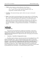
The voltage representing the temperatures at Zero and at Full-Scale are set on the
millivolt source to obtain the two calibration points. Use Table 2 to convert each temperature to
its equivalent millivolts (Reference = 0oC) for the thermocouple type used.
TABLE 2: Thermocouple Voltages vs. Temperature:
(Reference: National Bureau of Standards Thermocouple Tables)
Temp.
oC
-250
-200
-150
-100
-50
0
+50
+100
+150
+200
+250
+300
+350
+400
+450
+500
+550
+600
+650
+700
+800
+900
+1000
+1200
+1400
+1600
+1700
+1750
+1800
Thermoelectric
J
-7.890
-6.499
-4.632
-2.431
0.000
2.585
5.268
8.008
10.777
13.553
16.325
19.089
21.846
24.607
27.388
30.210
33.096
36.066
39.130
Voltage in Millivolts
K
T
E
-6.404
-5.891
-4.912
-3.553
-1.889
0.000
2.022
4.095
6.137
8.137
10.151
12.207
14.292
16.395
18.513
20.640
22.772
24.902
27.022
29.128
33.277
37.325
41.269
48.828
-6.181
-5.603
-4.648
-3.378
-1.819
0.000
2.035
4.277
6.702
9.286
12.011
14.860
17.816
20.869
- 12 -
-9.719
-8.824
-7.279
-5.237
-2.787
0.000
3.047
6.317
9.787
13.419
17.178
21.033
24.961
28.943
32.960
36.999
41.045
45.085
49.109
53.110
61.022
68.783
76.358
(Ref. Junction at 0oC)
R
S
B
0.000
0.296
0.647
1.041
1.468
1.923
2.400
2.896
3.407
3.933
4.471
5.021
5.582
6.155
6.741
7.949
9.203
10.503
13.224
16.035
18.842
20.215
20.878
0.000
0.299
0.645
1.029
1.440
1.873
2.323
2.786
3.260
3.743
4.234
4.732
5.237
5.751
6.274
7.345
8.448
9.585
11.947
14.368
16.771
17.942
18.504
0.000
1.002
1.241
1.505
1.791
2.100
2.430
3.154
3.957
4.833
6.783
8.952
11.257
12.462
13.008
13.585
Series 350T User’s Manual
Millivolt/Thermocouple
Transmitter - Calibration Example:
MODEL: 350T-TC1-Y-DIN-NCR
Input: 100 to 400oC., Type J Thermocouple, TC Break: Upscale
Output: 4 to 20mA DC
NOTE: To obtain the most accurate calibration of thermocouple
transmitters, apply power to the unit and allow several minutes for
thermal stabilization before completing calibration.
1. Set the input source to 5.268mV (100oC). Adjust the Zero (Z) pot until the output reads
4.000mA DC.
2. Set the input source to 21.846mV (400oC). Adjust the Span (S)pot until the output reads
20.000mA DC.
3. Repeat steps 1 and 2 above, until the readings converge. The instrument is now calibrated.
Several mid-point values should also be checked to verify proper operation of the transmitter.
Remember that the transmitter will be linear with millivolts and not temperature, unless the
transmitter includes a linearizer, only then will it will be linear with temperature. NOTE: If
a transmitter is linearized, the transmitter can only be trimmed to the range specified on the
label - no other range of calibration will give acceptable results.
4. After the above calibration procedure is complete, install the transmitter PC Board assembly
back into its case as described in the assembly procedure below.
Assembly Procedure for the 350T Plastic Housing:
NOTE: The Model/Serial Number label is attached to the left plastic side.
1. Refer to drawing 4501-251 and line up the left plastic side with the board and terminal
assembly. Carefully but firmly press the pieces together.
2. Before installing the right side, place the mounting bracket (unique to the mounting type you
have) around the pins at the back of the housing.
3. Line up the right side of the housing with the assembly and carefully but firmly press the
pieces together.
GENERAL MAINTENANCE:
The transmitter contains solid-state components and requires no maintenance except for periodic
cleaning and calibration verification. When a failure is suspected, a convenient method for
identifying a faulty transmitter is to exchange it with a known good unit. It is highly
recommended that a non-functioning transmitter be returned to Acromag for repair, since
Acromag makes use of tested and burned-in parts, and in some cases, parts that have been
selected for characteristics beyond that specified by the manufacturer. Further, Acromag has
automated test equipment that thoroughly checks the performance of each transmitter.
- 13 -